EP1377126A1 - Induction cooktop - Google Patents
Induction cooktop Download PDFInfo
- Publication number
- EP1377126A1 EP1377126A1 EP03010965A EP03010965A EP1377126A1 EP 1377126 A1 EP1377126 A1 EP 1377126A1 EP 03010965 A EP03010965 A EP 03010965A EP 03010965 A EP03010965 A EP 03010965A EP 1377126 A1 EP1377126 A1 EP 1377126A1
- Authority
- EP
- European Patent Office
- Prior art keywords
- terminal
- current
- connection
- electronic switch
- induction cooktop
- Prior art date
- Legal status (The legal status is an assumption and is not a legal conclusion. Google has not performed a legal analysis and makes no representation as to the accuracy of the status listed.)
- Granted
Links
- 230000006698 induction Effects 0.000 title claims abstract description 17
- 239000003990 capacitor Substances 0.000 claims abstract description 23
- 238000010438 heat treatment Methods 0.000 claims description 6
- 229910003460 diamond Inorganic materials 0.000 claims description 2
- 239000010432 diamond Substances 0.000 claims description 2
- 230000001360 synchronised effect Effects 0.000 claims description 2
- 102000003814 Interleukin-10 Human genes 0.000 claims 1
- 108090000174 Interleukin-10 Proteins 0.000 claims 1
- 238000005259 measurement Methods 0.000 description 6
- 238000010586 diagram Methods 0.000 description 4
- 238000000034 method Methods 0.000 description 4
- 238000005070 sampling Methods 0.000 description 4
- 230000002860 competitive effect Effects 0.000 description 1
- 230000002596 correlated effect Effects 0.000 description 1
- 230000000694 effects Effects 0.000 description 1
- 238000002474 experimental method Methods 0.000 description 1
- 239000002184 metal Substances 0.000 description 1
- 239000000126 substance Substances 0.000 description 1
- 238000004804 winding Methods 0.000 description 1
Images




Classifications
-
- H—ELECTRICITY
- H05—ELECTRIC TECHNIQUES NOT OTHERWISE PROVIDED FOR
- H05B—ELECTRIC HEATING; ELECTRIC LIGHT SOURCES NOT OTHERWISE PROVIDED FOR; CIRCUIT ARRANGEMENTS FOR ELECTRIC LIGHT SOURCES, IN GENERAL
- H05B6/00—Heating by electric, magnetic or electromagnetic fields
- H05B6/02—Induction heating
- H05B6/06—Control, e.g. of temperature, of power
- H05B6/062—Control, e.g. of temperature, of power for cooking plates or the like
-
- H—ELECTRICITY
- H05—ELECTRIC TECHNIQUES NOT OTHERWISE PROVIDED FOR
- H05B—ELECTRIC HEATING; ELECTRIC LIGHT SOURCES NOT OTHERWISE PROVIDED FOR; CIRCUIT ARRANGEMENTS FOR ELECTRIC LIGHT SOURCES, IN GENERAL
- H05B6/00—Heating by electric, magnetic or electromagnetic fields
- H05B6/02—Induction heating
- H05B6/04—Sources of current
Definitions
- the present invention refers to an improved kind of induction cooktop that uses an inverter circuit (or, more simply, an inverter) which generates a variable magnetic field in order to heat up a metal object, usually the bottom of a pan or pot.
- an inverter circuit or, more simply, an inverter which generates a variable magnetic field in order to heat up a metal object, usually the bottom of a pan or pot.
- the above-mentioned inverter circuit is provided with an induction coil and a resonance capacitor, which is adapted to resonate with said induction coil.
- the invention is substantially based on the experimentally verified consideration that, in some portions of the power-supply circuit, the high-frequency alternating current of the heating coil is not constant, but is rather subject to significant variations during the different phases of which each single complete cycle of operation is formed. Therefore, an attempt has been made to improve the circuit according to the prior-art by modifying and/or expanding it, and to identify, within the various phases making up the complete cycle, current values that are individually capable of being correlated with both the power-supply current and the resonance current.
- an induction cooktop according to the present invention comprises:
- a second resonance capacitor C1 is provided between said second terminal 6 of said heating coil L20 and said second terminal 15 of said filter capacitor C5; in addition, the current-conducting link 16 between said second terminal 15 and said connection 11 (which connects the second extreme 9 of said electronic switch circuits at a branch point A, to which there is connected also the connection with said first terminal 10 of said filter inductor L10) is provided with a current transformer TA, whose primary winding is represented by the coil L1 illustrated in Figure 3.
- the individual complete cycle may be broken down into four distinct phases 1, 2, 3 and 4, in which the current pattern is as symbolically represented in Figures 4, 5, 6 and 7, respectively.
- the current I(L10) is sensibly constant and, furthermore, of known magnitude owing to its being measured during the afore defined phase 3 of the cycle; as a result, by measuring the current I(L1) during this phase 1 it is possible for the desired resonance current I(L20) to be found out by calculation according to the above-indicated relation.
Landscapes
- Physics & Mathematics (AREA)
- Electromagnetism (AREA)
- Inverter Devices (AREA)
- General Induction Heating (AREA)
- Surgical Instruments (AREA)
- Induction Heating Cooking Devices (AREA)
- Magnetic Heads (AREA)
- Liquid Crystal (AREA)
- Dry Shavers And Clippers (AREA)
- Polishing Bodies And Polishing Tools (AREA)
Abstract
Description
- The present invention refers to an improved kind of induction cooktop that uses an inverter circuit (or, more simply, an inverter) which generates a variable magnetic field in order to heat up a metal object, usually the bottom of a pan or pot.
- The above-mentioned inverter circuit is provided with an induction coil and a resonance capacitor, which is adapted to resonate with said induction coil.
- In "consumer" applications, i.e. when these induction cooktops are intended for use in applications that generally and specifically involve the so-called electric home appliances, said cooktops simply cannot escape from the general requirements that peculiarly apply to this special market, in which the products intended therefore shall among other things have absolutely competitive costs and prices combined with a reliability that must not only be substantial and sizeable, but also capable of being guaranteed throughout the first years of the product life.
- In the light of these considerations, one of the basic requirements that most of all seems to demand appropriate compliance in connection with these kinds of cooktops relates to the capability for both the current flowing through the heating or resonance coil and the total current entering the circuit to be measured to an adequate extent of accuracy to properly meet both operating, i.e. practical and safety needs.
- Various solutions have been found and proposed in the art in view of complying with this requirement; a typical one among such solutions is illustrated in the accompanying Figure 1A, in which the currents in said respective circuits are measured conventionally by means of respective current transformers (CT1, CT2).
- While such a solution turns out to be fully satisfactory from a point of view of general performance capabilities, it is certainly less so from an economic point of view, since the presence of two current transformers, which are inherently rather expensive devices, practically thwarts the general effort aimed at reducing costs.
- In view of overcoming such a drawback, the circuit solution illustrated symbolically in the accompanying Figure 1B is therefore been adopted. This solution provides for a single current transformer to be connected in series with the filter capacitor Cf, and further provides for the resonance coil to be connected in series with a single resonance capacitor Cr1.
- Although it seemingly appears to be capable of ensuring an adequate compliance with the above-cited requirements, when a closer look is taken at it this particular solution turns however out as being still too costly, since it has been found experimentally that, for the same general conditions and parameters and, in particular, for the same the power output, said filter capacitor must be rated at a capacitance that is substantially twice as much as the capacitance rating of the filter capacitor used in the previously cited circuit with two resonance capacitors.
- It would therefore be desirable, and is actually a main purpose of the present invention, to provide an induction cooktop which is capable of operating and being controlled with a single current transformer and, at the same time, does not involve any unsustainable increase in costs and/or in the electric and thermal load imposed to the other component parts.
- According to the present invention, the above-indicated aim is reached in a particular kind of induction cooktop that incorporates the characteristics as recited in the appended claims and is described below by way of non-limiting example with reference to the accompanying drawings, in which:
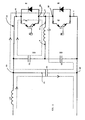
- Figure 2 is a schematic view of a circuit arrangement of an embodiment of the induction cooktop according to the present invention;
- Figure 3 is a schematic view of the same circuit arrangement shown in Figure 2, in which the arrangement of the current transformer according to the present invention is however shown more explicitly;
- Figures 4, 5, 6 and 7 are diagrammatical views showing the flow pattern of the currents in the circuit arrangement of Figure 2 in four successive operating phases of the induction cooktop, respectively;
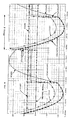
- Figure 8 is a diagrammatical view of the pattern followed by some currents of the circuit of the invention during a specific operating phase; and
- Figure 9 is a diagrammatical view of the pattern followed by some other currents of the circuit of the invention during another specific operating phase.
- The invention is substantially based on the experimentally verified consideration that, in some portions of the power-supply circuit, the high-frequency alternating current of the heating coil is not constant, but is rather subject to significant variations during the different phases of which each single complete cycle of operation is formed. Therefore, an attempt has been made to improve the circuit according to the prior-art by modifying and/or expanding it, and to identify, within the various phases making up the complete cycle, current values that are individually capable of being correlated with both the power-supply current and the resonance current.
- In substance, the attempt has been made to sample the current in a particular portion of the circuit at specific instants, and to process the results of such a sampling so as to calculate, or directly measure, the currents being investigated.
- These attempts have led to an absolutely positive outcome and the peculiarities, i.e. ways and means of the resulting solution are described below.
- With reference to Figure 2, an induction cooktop according to the present invention comprises:
- a half-bridge inverter circuit with a first and a second electronic switch or diamond circuit (E.S.C.) D1 - T1 and D2 - T2, for instance of the IGBT (Insulated Gate Bipolar Transistor) type, connected in series via a
connection 3 between two common terminals G1, G2, and controlled by means of respective driving signals that are sent to respective circuits P1, P2; - a heating coil L20 for a high-frequency electric current adapted to inductively heat up an appropriate object to flow therethrough, this coil being connected with a
first terminal 5 thereof to saidconnection 3; - the
second terminal 6 of this coil being connected to the terminal of a first resonance capacitor C2; - a filter capacitor C5 connected with a first terminal G4 to an extreme 7 (not connected to said connection 3) of said electronic switch circuits and with the respective
second terminal 15 to afirst terminal 10 of a filter inductor L10, the opposite terminal of which is connected to the power supply; - a
connection 11 that connects the second extreme 9 (not connected to said connection 3) of said electronic switch circuits to said first extreme 10 of said filter inductor L10. - According to the present invention, a second resonance capacitor C1 is provided between said
second terminal 6 of said heating coil L20 and saidsecond terminal 15 of said filter capacitor C5; in addition, the current-conductinglink 16 between saidsecond terminal 15 and said connection 11 (which connects the second extreme 9 of said electronic switch circuits at a branch point A, to which there is connected also the connection with saidfirst terminal 10 of said filter inductor L10) is provided with a current transformer TA, whose primary winding is represented by the coil L1 illustrated in Figure 3. - Owing to the effect of such a capacitor C1, the individual complete cycle may be broken down into four
distinct phases - Let us now consider the
phase 1 of said complete cycle: throughout the extensive experimental work that has been carried out in this connection, it has been found, on the basis of the measurements performed, that the pattern of the driving currents, the resonance current I (L20), the current of the filter coil I (L10), and the current in the current transformer I (L1) is as represented in the diagram appearing in Figure 8; from this diagram it may be noticed that, as far as thesole phase 1 is concerned, the following experimental relation applies:
- The fact shall however be taken into due consideration that the current I(L10) is sensibly constant and, furthermore, of known magnitude owing to its being measured during the afore defined
phase 3 of the cycle; as a result, by measuring the current I(L1) during thisphase 1 it is possible for the desired resonance current I(L20) to be found out by calculation according to the above-indicated relation. - The possibility is in this way fully demonstrated for said resonance current to be calculated provided that the measurement, i.e. the sampling is carried out at a point lying precisely and surely within this defined
phase 1. Anyway, such a requirement is readily and quite easily complied with through an accurate synchronization of such a current measurement with the driving signals of the electronic switch circuits on the driving circuits P1 and P2. - The
phase 3 of the cycle shall be considered next. Following a logic and methodological procedure fully similar to the afore explained one, during the various experiments that have been conducted it has been found by measurement that the pattern of the driving currents, the input current I (L10), the current on the capacitor C5, and the current on the capacitor C1 is as represented in the diagram appearing in Figure 9; from this diagram it may be noticed that, as far as thesole phase 3 is concerned, the following experimental relation applies:
- However, owing to the fact that the currents in C5 and C1 practically deplete the current flowing through the primary coil of the transformer TA, it ensues that there is no current in the branch of the electronic switch circuits. Therefore, the current that is to be measured in the secondary coil of the transformer TA provides an accurate measure of the input current I(L10).
- Again, the possibility is in this way fully demonstrated for said input current to be directly measured provided that the measurement, i.e. the sampling is carried out at a point lying precisely and surely within this defined
phase 3, wherein such a requirement is readily and quite easily complied with through an accurate synchronization of such a current measurement with the driving signals of the electronic switch circuits on the driving circuits P1 and P2. - The electronic techniques to be used and the procedures to be followed in order to carry out such current samplings in a synchronized manner as indicated above are fully within the abilities of those skilled in the art, so that they shall not be explained here any closer.
Claims (5)
- Induction cooktop, in particular for home use, comprising:- a half-bridge inverter circuit with a first and a second electronic switch or diamond circuit (D1 - T1, D2 - T2) connected in series via a connection (3) between two common terminals (G1, G2) of said electronic switch circuits;- a resonant heating coil (L20) for a high-frequency electric current adapted to inductively heat up an appropriate object to flow therethrough, this coil being connected with a first terminal (5) thereof to said connection (3), and with the second terminal (6) thereof to the terminal of a first resonance capacitor (C2);- a filter capacitor (C5) connected with a first terminal (G4) thereof to an extreme (7), not connected to said connection (3), of said electronic switch circuits, and with the second terminal (15) thereof to a first terminal (10) of a filter inductor (L10), the opposite terminal of which is connected to the power supply;- a connection (11) that connects the second extreme (9), not connected to said connection (3), of said electronic switch circuits to said first terminal (10) of said filter inductor (L10),characterized in that a second resonance capacitor (C1) is provided- between said second terminal (6) of said heating coil (L20)- and said second terminal (15) of said filter capacitor (C5);
and in that- the current-conducting link (16) between said second terminal (15) and said connection (11) connects the second extreme (9) of said electronic switch circuits at a branch point (A), to which there is connected also the connection with said first terminal (10) of said filter inductor (L10). - Induction cooktop according to claim 1, characterized in that there is provided a current transformer (TA) connected in series to said current-conducting link (16).
- Induction cooktop according to claim 1 or 2, characterized in that the input current (IL10) and the resonance current (IL20) of said induction cooktop are calculated and/or measured on the basis of distinct readings of the current measured by said current transformer (TA).
- Induction cooktop according to claim 3, characterized in that said current readings on said current transformer (TA) are selectively synchronized with two respective driving signals on respective driving circuits (P1, P2) of said electronic switch circuits (D1-T1, D2-T2).
- Induction cooktop according to claim 4, characterized in that said two driving signals correspond to the conditions of:T1 = OFF, T2 = ON (Phase 3) andT1 = ON, T2 = OFF (Phase 1), respectively.
Applications Claiming Priority (2)
| Application Number | Priority Date | Filing Date | Title |
|---|---|---|---|
| IT2002PN000043A ITPN20020043A1 (en) | 2002-06-19 | 2002-06-19 | INDUCTION HOB. |
| ITPN20020043 | 2002-06-19 |
Publications (2)
| Publication Number | Publication Date |
|---|---|
| EP1377126A1 true EP1377126A1 (en) | 2004-01-02 |
| EP1377126B1 EP1377126B1 (en) | 2006-11-29 |
Family
ID=29717162
Family Applications (1)
| Application Number | Title | Priority Date | Filing Date |
|---|---|---|---|
| EP03010965A Expired - Lifetime EP1377126B1 (en) | 2002-06-19 | 2003-05-16 | Induction cooktop |
Country Status (6)
| Country | Link |
|---|---|
| EP (1) | EP1377126B1 (en) |
| AT (1) | ATE347246T1 (en) |
| DE (1) | DE60309974T2 (en) |
| DK (1) | DK1377126T3 (en) |
| ES (1) | ES2278088T3 (en) |
| IT (1) | ITPN20020043A1 (en) |
Cited By (1)
| Publication number | Priority date | Publication date | Assignee | Title |
|---|---|---|---|---|
| EP3419382A1 (en) * | 2017-06-23 | 2018-12-26 | Vestel Elektronik Sanayi ve Ticaret A.S. | Induction cooker and a method of operation |
Citations (2)
| Publication number | Priority date | Publication date | Assignee | Title |
|---|---|---|---|---|
| EP0817531A2 (en) * | 1996-06-26 | 1998-01-07 | Balay S.A. | Flexible and re-configurable topology |
| US6288378B1 (en) * | 1999-03-01 | 2001-09-11 | Powell Power Electronics, Inc. | Induction heating system with split resonance capacitance |
-
2002
- 2002-06-19 IT IT2002PN000043A patent/ITPN20020043A1/en unknown
-
2003
- 2003-05-16 AT AT03010965T patent/ATE347246T1/en not_active IP Right Cessation
- 2003-05-16 DK DK03010965T patent/DK1377126T3/en active
- 2003-05-16 EP EP03010965A patent/EP1377126B1/en not_active Expired - Lifetime
- 2003-05-16 ES ES03010965T patent/ES2278088T3/en not_active Expired - Lifetime
- 2003-05-16 DE DE60309974T patent/DE60309974T2/en not_active Expired - Lifetime
Patent Citations (2)
| Publication number | Priority date | Publication date | Assignee | Title |
|---|---|---|---|---|
| EP0817531A2 (en) * | 1996-06-26 | 1998-01-07 | Balay S.A. | Flexible and re-configurable topology |
| US6288378B1 (en) * | 1999-03-01 | 2001-09-11 | Powell Power Electronics, Inc. | Induction heating system with split resonance capacitance |
Non-Patent Citations (3)
| Title |
|---|
| KOERTZEN H W ET AL: "Design of the half-bridge, series resonant converter for induction cooking", POWER ELECTRONICS SPECIALISTS CONFERENCE, 1995. PESC '95 RECORD., 26TH ANNUAL IEEE ATLANTA, GA, USA 18-22 JUNE 1995, NEW YORK, NY, USA,IEEE, US, 18 June 1995 (1995-06-18), pages 729 - 735, XP010150634, ISBN: 0-7803-2730-6 * |
| KOERTZEN H W ET AL: "Single shot surface heating series resonant converter with ZCS and an uncontrolled DC link voltage", INDUSTRY APPLICATIONS CONFERENCE, 1995. THIRTIETH IAS ANNUAL MEETING, IAS '95., CONFERENCE RECORD OF THE 1995 IEEE ORLANDO, FL, USA 8-12 OCT. 1995, NEW YORK, NY, USA,IEEE, US, 8 October 1995 (1995-10-08), pages 1957 - 1963, XP010193309, ISBN: 0-7803-3008-0 * |
| PALMER P R ET AL: "AN MCT BASED INDUSTRIAL INDUCTION COOKER CIRCUIT USING ZERO CURRENTSWITCHING", EPE '95: 6TH. EUROPEAN CONFERENCE ON POWER ELECTRONICS AND APPLICATIONS. SEVILLA, SEPT. 19 - 21, 1995, EUROPEAN CONFERENCE ON POWER ELECTRONICS AND APPLICATIONS, BRUSSELS, EPE ASSOCIATION, B, vol. 2 CONF. 6, 19 September 1995 (1995-09-19), pages 2677 - 2682, XP000537803 * |
Cited By (1)
| Publication number | Priority date | Publication date | Assignee | Title |
|---|---|---|---|---|
| EP3419382A1 (en) * | 2017-06-23 | 2018-12-26 | Vestel Elektronik Sanayi ve Ticaret A.S. | Induction cooker and a method of operation |
Also Published As
| Publication number | Publication date |
|---|---|
| DE60309974D1 (en) | 2007-01-11 |
| ES2278088T3 (en) | 2007-08-01 |
| ATE347246T1 (en) | 2006-12-15 |
| ITPN20020043A1 (en) | 2003-12-19 |
| EP1377126B1 (en) | 2006-11-29 |
| DE60309974T2 (en) | 2007-06-21 |
| DK1377126T3 (en) | 2008-01-07 |
Similar Documents
| Publication | Publication Date | Title |
|---|---|---|
| EP3206461B1 (en) | Induction-heating cooking system and controlling process thereof | |
| US11979034B2 (en) | Foreign object detection in a wireless power transfer system | |
| CN104770061B (en) | Induction heating cooking instrument | |
| EP2790466B1 (en) | Induction heating device | |
| US8299407B2 (en) | Electromagnetic induction heating device | |
| CA2639157C (en) | An improved induction cooking appliance and a method for checking the cooking capabilities of a piece of cookware | |
| JP5844017B1 (en) | Induction heating cooker and control method thereof | |
| US9826576B2 (en) | Induction heating cooker | |
| US20110253706A1 (en) | Heating device with plural induction coils | |
| EP3612004B1 (en) | Induction heating apparatus | |
| JP2013073939A (en) | Method for heating cooking container with induction heating apparatus and induction heating apparatus | |
| KR100629334B1 (en) | Induction heating cooker and its operation method | |
| EP3836754B1 (en) | Cooking apparatus | |
| WO2015059801A1 (en) | Induction heating cooker | |
| CA2690205A1 (en) | Induction cooking heater and method for the control thereof | |
| EP1377126B1 (en) | Induction cooktop | |
| WO2015059802A1 (en) | Induction heating cooker | |
| EP2571331B1 (en) | An induction generator for induction heating devices and a method for the operation of an induction generator for induction heating elements | |
| CN113654678B (en) | Heating temperature measurement circuit, temperature measurement method thereof, cooking device and storage medium | |
| KR100518167B1 (en) | An induction heating type cooking apparatus using a self-oscilating type half-bridge driver IC | |
| JP2002299028A (en) | Induction heating cooker | |
| US5914066A (en) | Circuit for the control of energy supply in a resonance converter | |
| JP7233390B2 (en) | Induction heating coil and induction heating device | |
| JP3800808B2 (en) | Induction heating inverter device | |
| EP3872960A1 (en) | Wireless power transmission apparatus for induction heating and control method thereof |
Legal Events
| Date | Code | Title | Description |
|---|---|---|---|
| PUAI | Public reference made under article 153(3) epc to a published international application that has entered the european phase |
Free format text: ORIGINAL CODE: 0009012 |
|
| AK | Designated contracting states |
Kind code of ref document: A1 Designated state(s): AT BE BG CH CY CZ DE DK EE ES FI FR GB GR HU IE IT LI LU MC NL PT RO SE SI SK TR |
|
| AX | Request for extension of the european patent |
Extension state: AL LT LV MK |
|
| 17P | Request for examination filed |
Effective date: 20040526 |
|
| 17Q | First examination report despatched |
Effective date: 20040624 |
|
| AKX | Designation fees paid |
Designated state(s): AT BE BG CH CY CZ DE DK EE ES FI FR GB GR HU IE IT LI LU MC NL PT RO SE SI SK TR |
|
| GRAP | Despatch of communication of intention to grant a patent |
Free format text: ORIGINAL CODE: EPIDOSNIGR1 |
|
| GRAS | Grant fee paid |
Free format text: ORIGINAL CODE: EPIDOSNIGR3 |
|
| GRAA | (expected) grant |
Free format text: ORIGINAL CODE: 0009210 |
|
| AK | Designated contracting states |
Kind code of ref document: B1 Designated state(s): AT BE BG CH CY CZ DE DK EE ES FI FR GB GR HU IE IT LI LU MC NL PT RO SE SI SK TR |
|
| PG25 | Lapsed in a contracting state [announced via postgrant information from national office to epo] |
Ref country code: IT Free format text: LAPSE BECAUSE OF FAILURE TO SUBMIT A TRANSLATION OF THE DESCRIPTION OR TO PAY THE FEE WITHIN THE PRESCRIBED TIME-LIMIT;WARNING: LAPSES OF ITALIAN PATENTS WITH EFFECTIVE DATE BEFORE 2007 MAY HAVE OCCURRED AT ANY TIME BEFORE 2007. THE CORRECT EFFECTIVE DATE MAY BE DIFFERENT FROM THE ONE RECORDED. Effective date: 20061129 Ref country code: FI Free format text: LAPSE BECAUSE OF FAILURE TO SUBMIT A TRANSLATION OF THE DESCRIPTION OR TO PAY THE FEE WITHIN THE PRESCRIBED TIME-LIMIT Effective date: 20061129 Ref country code: SI Free format text: LAPSE BECAUSE OF FAILURE TO SUBMIT A TRANSLATION OF THE DESCRIPTION OR TO PAY THE FEE WITHIN THE PRESCRIBED TIME-LIMIT Effective date: 20061129 Ref country code: SK Free format text: LAPSE BECAUSE OF FAILURE TO SUBMIT A TRANSLATION OF THE DESCRIPTION OR TO PAY THE FEE WITHIN THE PRESCRIBED TIME-LIMIT Effective date: 20061129 Ref country code: LI Free format text: LAPSE BECAUSE OF FAILURE TO SUBMIT A TRANSLATION OF THE DESCRIPTION OR TO PAY THE FEE WITHIN THE PRESCRIBED TIME-LIMIT Effective date: 20061129 Ref country code: AT Free format text: LAPSE BECAUSE OF FAILURE TO SUBMIT A TRANSLATION OF THE DESCRIPTION OR TO PAY THE FEE WITHIN THE PRESCRIBED TIME-LIMIT Effective date: 20061129 Ref country code: BE Free format text: LAPSE BECAUSE OF FAILURE TO SUBMIT A TRANSLATION OF THE DESCRIPTION OR TO PAY THE FEE WITHIN THE PRESCRIBED TIME-LIMIT Effective date: 20061129 Ref country code: CZ Free format text: LAPSE BECAUSE OF FAILURE TO SUBMIT A TRANSLATION OF THE DESCRIPTION OR TO PAY THE FEE WITHIN THE PRESCRIBED TIME-LIMIT Effective date: 20061129 Ref country code: NL Free format text: LAPSE BECAUSE OF FAILURE TO SUBMIT A TRANSLATION OF THE DESCRIPTION OR TO PAY THE FEE WITHIN THE PRESCRIBED TIME-LIMIT Effective date: 20061129 Ref country code: RO Free format text: LAPSE BECAUSE OF FAILURE TO SUBMIT A TRANSLATION OF THE DESCRIPTION OR TO PAY THE FEE WITHIN THE PRESCRIBED TIME-LIMIT Effective date: 20061129 Ref country code: CH Free format text: LAPSE BECAUSE OF FAILURE TO SUBMIT A TRANSLATION OF THE DESCRIPTION OR TO PAY THE FEE WITHIN THE PRESCRIBED TIME-LIMIT Effective date: 20061129 |
|
| REG | Reference to a national code |
Ref country code: GB Ref legal event code: FG4D |
|
| REG | Reference to a national code |
Ref country code: CH Ref legal event code: EP |
|
| REG | Reference to a national code |
Ref country code: IE Ref legal event code: FG4D |
|
| REF | Corresponds to: |
Ref document number: 60309974 Country of ref document: DE Date of ref document: 20070111 Kind code of ref document: P |
|
| REG | Reference to a national code |
Ref country code: SE Ref legal event code: TRGR |
|
| PG25 | Lapsed in a contracting state [announced via postgrant information from national office to epo] |
Ref country code: BG Free format text: LAPSE BECAUSE OF FAILURE TO SUBMIT A TRANSLATION OF THE DESCRIPTION OR TO PAY THE FEE WITHIN THE PRESCRIBED TIME-LIMIT Effective date: 20070228 |
|
| PG25 | Lapsed in a contracting state [announced via postgrant information from national office to epo] |
Ref country code: PT Free format text: LAPSE BECAUSE OF FAILURE TO SUBMIT A TRANSLATION OF THE DESCRIPTION OR TO PAY THE FEE WITHIN THE PRESCRIBED TIME-LIMIT Effective date: 20070430 |
|
| NLV1 | Nl: lapsed or annulled due to failure to fulfill the requirements of art. 29p and 29m of the patents act | ||
| REG | Reference to a national code |
Ref country code: CH Ref legal event code: PL |
|
| ET | Fr: translation filed | ||
| REG | Reference to a national code |
Ref country code: ES Ref legal event code: FG2A Ref document number: 2278088 Country of ref document: ES Kind code of ref document: T3 |
|
| PLBE | No opposition filed within time limit |
Free format text: ORIGINAL CODE: 0009261 |
|
| STAA | Information on the status of an ep patent application or granted ep patent |
Free format text: STATUS: NO OPPOSITION FILED WITHIN TIME LIMIT |
|
| 26N | No opposition filed |
Effective date: 20070830 |
|
| REG | Reference to a national code |
Ref country code: DK Ref legal event code: T3 |
|
| PG25 | Lapsed in a contracting state [announced via postgrant information from national office to epo] |
Ref country code: MC Free format text: LAPSE BECAUSE OF NON-PAYMENT OF DUE FEES Effective date: 20070531 |
|
| PG25 | Lapsed in a contracting state [announced via postgrant information from national office to epo] |
Ref country code: GR Free format text: LAPSE BECAUSE OF FAILURE TO SUBMIT A TRANSLATION OF THE DESCRIPTION OR TO PAY THE FEE WITHIN THE PRESCRIBED TIME-LIMIT Effective date: 20070301 |
|
| PG25 | Lapsed in a contracting state [announced via postgrant information from national office to epo] |
Ref country code: IE Free format text: LAPSE BECAUSE OF NON-PAYMENT OF DUE FEES Effective date: 20070516 |
|
| PG25 | Lapsed in a contracting state [announced via postgrant information from national office to epo] |
Ref country code: EE Free format text: LAPSE BECAUSE OF FAILURE TO SUBMIT A TRANSLATION OF THE DESCRIPTION OR TO PAY THE FEE WITHIN THE PRESCRIBED TIME-LIMIT Effective date: 20061129 |
|
| PGFP | Annual fee paid to national office [announced via postgrant information from national office to epo] |
Ref country code: DK Payment date: 20090525 Year of fee payment: 7 |
|
| PG25 | Lapsed in a contracting state [announced via postgrant information from national office to epo] |
Ref country code: LU Free format text: LAPSE BECAUSE OF NON-PAYMENT OF DUE FEES Effective date: 20070516 Ref country code: CY Free format text: LAPSE BECAUSE OF FAILURE TO SUBMIT A TRANSLATION OF THE DESCRIPTION OR TO PAY THE FEE WITHIN THE PRESCRIBED TIME-LIMIT Effective date: 20061129 |
|
| PGFP | Annual fee paid to national office [announced via postgrant information from national office to epo] |
Ref country code: SE Payment date: 20090519 Year of fee payment: 7 |
|
| PG25 | Lapsed in a contracting state [announced via postgrant information from national office to epo] |
Ref country code: HU Free format text: LAPSE BECAUSE OF FAILURE TO SUBMIT A TRANSLATION OF THE DESCRIPTION OR TO PAY THE FEE WITHIN THE PRESCRIBED TIME-LIMIT Effective date: 20070530 Ref country code: TR Free format text: LAPSE BECAUSE OF FAILURE TO SUBMIT A TRANSLATION OF THE DESCRIPTION OR TO PAY THE FEE WITHIN THE PRESCRIBED TIME-LIMIT Effective date: 20061129 |
|
| PGFP | Annual fee paid to national office [announced via postgrant information from national office to epo] |
Ref country code: GB Payment date: 20090521 Year of fee payment: 7 |
|
| REG | Reference to a national code |
Ref country code: DK Ref legal event code: EBP |
|
| GBPC | Gb: european patent ceased through non-payment of renewal fee |
Effective date: 20100516 |
|
| EUG | Se: european patent has lapsed | ||
| PG25 | Lapsed in a contracting state [announced via postgrant information from national office to epo] |
Ref country code: SE Free format text: LAPSE BECAUSE OF NON-PAYMENT OF DUE FEES Effective date: 20100517 |
|
| PG25 | Lapsed in a contracting state [announced via postgrant information from national office to epo] |
Ref country code: DK Free format text: LAPSE BECAUSE OF NON-PAYMENT OF DUE FEES Effective date: 20100531 |
|
| PG25 | Lapsed in a contracting state [announced via postgrant information from national office to epo] |
Ref country code: GB Free format text: LAPSE BECAUSE OF NON-PAYMENT OF DUE FEES Effective date: 20100516 |
|
| REG | Reference to a national code |
Ref country code: DE Ref legal event code: R082 Ref document number: 60309974 Country of ref document: DE Representative=s name: GERHARD BAUMGARTL, DE Ref country code: DE Ref legal event code: R082 Ref document number: 60309974 Country of ref document: DE Representative=s name: BAUMGARTL, GERHARD, DIPL.-ING.UNIV., DE |
|
| PGFP | Annual fee paid to national office [announced via postgrant information from national office to epo] |
Ref country code: ES Payment date: 20120525 Year of fee payment: 10 |
|
| PGFP | Annual fee paid to national office [announced via postgrant information from national office to epo] |
Ref country code: DE Payment date: 20130522 Year of fee payment: 11 |
|
| PGFP | Annual fee paid to national office [announced via postgrant information from national office to epo] |
Ref country code: FR Payment date: 20130603 Year of fee payment: 11 |
|
| REG | Reference to a national code |
Ref country code: DE Ref legal event code: R119 Ref document number: 60309974 Country of ref document: DE |
|
| REG | Reference to a national code |
Ref country code: DE Ref legal event code: R119 Ref document number: 60309974 Country of ref document: DE Effective date: 20141202 |
|
| REG | Reference to a national code |
Ref country code: FR Ref legal event code: ST Effective date: 20150130 |
|
| PG25 | Lapsed in a contracting state [announced via postgrant information from national office to epo] |
Ref country code: DE Free format text: LAPSE BECAUSE OF NON-PAYMENT OF DUE FEES Effective date: 20141202 |
|
| PG25 | Lapsed in a contracting state [announced via postgrant information from national office to epo] |
Ref country code: FR Free format text: LAPSE BECAUSE OF NON-PAYMENT OF DUE FEES Effective date: 20140602 |
|
| REG | Reference to a national code |
Ref country code: ES Ref legal event code: FD2A Effective date: 20150630 |
|
| PG25 | Lapsed in a contracting state [announced via postgrant information from national office to epo] |
Ref country code: ES Free format text: LAPSE BECAUSE OF NON-PAYMENT OF DUE FEES Effective date: 20140517 |