EP1377117A1 - Internal magnetic circuit and loudspeaker system incorporating the same - Google Patents
Internal magnetic circuit and loudspeaker system incorporating the same Download PDFInfo
- Publication number
- EP1377117A1 EP1377117A1 EP03013872A EP03013872A EP1377117A1 EP 1377117 A1 EP1377117 A1 EP 1377117A1 EP 03013872 A EP03013872 A EP 03013872A EP 03013872 A EP03013872 A EP 03013872A EP 1377117 A1 EP1377117 A1 EP 1377117A1
- Authority
- EP
- European Patent Office
- Prior art keywords
- magnetic
- magnet
- gap
- yoke
- plate
- Prior art date
- Legal status (The legal status is an assumption and is not a legal conclusion. Google has not performed a legal analysis and makes no representation as to the accuracy of the status listed.)
- Withdrawn
Links
Images
Classifications
-
- H—ELECTRICITY
- H04—ELECTRIC COMMUNICATION TECHNIQUE
- H04R—LOUDSPEAKERS, MICROPHONES, GRAMOPHONE PICK-UPS OR LIKE ACOUSTIC ELECTROMECHANICAL TRANSDUCERS; ELECTRIC HEARING AIDS; PUBLIC ADDRESS SYSTEMS
- H04R9/00—Transducers of moving-coil, moving-strip, or moving-wire type
- H04R9/02—Details
- H04R9/025—Magnetic circuit
-
- H—ELECTRICITY
- H04—ELECTRIC COMMUNICATION TECHNIQUE
- H04R—LOUDSPEAKERS, MICROPHONES, GRAMOPHONE PICK-UPS OR LIKE ACOUSTIC ELECTROMECHANICAL TRANSDUCERS; ELECTRIC HEARING AIDS; PUBLIC ADDRESS SYSTEMS
- H04R9/00—Transducers of moving-coil, moving-strip, or moving-wire type
- H04R9/06—Loudspeakers
Definitions
- the present invention relates to an internal magnetic circuit having a magnet, a yoke, and a plate, and a loudspeaker system incorporating the magnetic circuit.
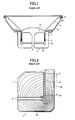
- Fig. 1 shows one prior art example of a loudspeaker system incorporating an internal magnetic circuit disclosed in Japanese Patent Laid-Open Publication No. Hei 6-261393, and Fig. 2 is an explanatory view showing the internal magnetic circuit.
- a vertically magnetized magnet 2 and a plate 1 forming a pole piece are arranged inside a yoke 3 having a bottom part 3a and a side part 3b surrounding the plate 1.
- the magnet 2 is attached to the bottom face of the plate 1 and to the bottom part 3a of the yoke 3.
- An air gap or magnetic gap G is formed between the plate 1 and the yoke 3.
- the magnet 2, the yoke 3 on the side of one magnetic pole of the magnet 2, the plate 1 on the side of the other magnetic pole of the magnet 2, and the magnetic gap G form an internal magnetic circuit.
- a voice coil bobbin 5 is arranged such as to surround the pillar-like plate 1 which forms the pole piece, so that a voice coil 4 is positioned inside the magnetic gap G .
- the voice coil bobbin 5 is supported on a frame 6 through a damper 7.
- the inner end of a diaphragm 8 is fixedly attached to the periphery of the voice coil bobbin 5, while the outer end of the diaphragm 8 is supported on the periphery of the frame 6 through an edge 8A.
- Reference numerals 9 and 10 represent a center cap and a gasket, respectively.
- This short voice coil design has the effect of preventing nonlinear distortion on condition that the magnetic flux distribution in the magnetic gap G is uniform.
- the magnetic flux density distribution inside the magnetic gap is not necessarily uniform particularly if it has a long effective length.
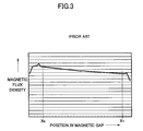
- Fig. 2 shows the magnetic circuit formed by the magnet 2, the yoke 3 and plate 1 arranged on the opposite sides of the magnet 2, and the magnetic gap G .
- most of the magnetic flux lines form loops leaving from one magnetic pole of the magnet 2, passing through the bottom part 3a and side part 3b of the yoke 3, crossing the magnetic gap G , passing the plate 1, and entering the other magnetic pole of the magnet.
- the density of these magnetic flux lines tends to be high on the side of shorter loops, i.e., the nearer the loops are to the magnet 2, the higher the density is, and vice versa.
- the magnetic flux density is higher on the X 0 side, while it is lower on the X 1 side.
- the magnetic flux density decreases in the direction of from X 0 to X 1 as shown in Fig. 3 within the effective length X 0 -X 1 , meaning that the magnetic flux density is not uniform in the direction in which the voice coil 4 moves.
- the present invention has been devised to resolve the above problem, and an object of the present invention is to provide a magnetic circuit having uniform magnetic flux density inside the magnetic gap along the direction of its length, and thereby to provide a loudspeaker system capable of outputting sound with less distortion.
- an internal magnetic circuit includes a magnet, a yoke arranged on one magnetic pole of the magnet, and a plate arranged on the other magnetic pole of the magnet.
- a magnetic gap is formed between the yoke and plate.
- a magnetic flux density inside the magnetic gap is made uniform by elongating a magnetic path length of magnetic flux, at a near side to said magnet, extending across said magnetic gap.
- the yoke in the internal magnetic circuit configured as described above, includes a gap for allowing a magnetic flux loop extending across the magnetic gap to detour, so that the magnetic path length of magnetic flux can be elongated.
- the yoke is made up of a bottom part attached to a bottom face of the magnet, a side part standing on a side of the plate, and a folded-back part which folds downward over the side part such as to face the magnetic gap.
- a loudspeaker system incorporating the internal magnetic circuit in any one of the first to third aspects, wherein a voice coil is positioned inside the magnetic gap.
- FIG. 4 illustrates an internal magnetic circuit according to the embodiment of the present invention, which includes a plate 20 forming a pole piece, a vertically magnetized magnet 21 attached to a bottom face of the plate 20, and a yoke 22 attached to a bottom face of the magnet 21. Between the plate 20 and yoke 22 is formed a magnetic gap G 0 .
- the primary feature of this embodiment is that the magnetic flux density inside the magnetic gap G 0 is made uniform by elongating the magnetic path length of part of the magnetic flux crossing the magnetic gap G 0 .
- the secondary feature of the embodiment is that the yoke 22 is formed with a gap 22a for allowing the magnetic flux loops crossing the magnetic gap G 0 to detour.
- the gap 22a is formed opposite the magnetic gap G 0 parallel thereto in the yoke 22, so that the magnetic flux loops make a detour around the gap 22a before reaching the magnetic gap G 0 . Accordingly, there is no concentration of shorter loops in the range of the effective length X 0 -X 1 inside the magnetic gap G 0 , and the magnetic flux density therein is made uniform.
- the third feature of the embodiment is that the yoke 22 is made up of a bottom part 22b which is attached to a bottom face of the magnet 21, a side part 22c standing upright on the side of the plate 20, and a folded-back part 22d which extends from the side part 22c and folds over downwardly to face the magnetic gap G 0 .
- the gap 22a can be formed between the side part 22c and folded-back part 22d of the yoke 22, without causing the yoke 22 to take up much space in the magnetic circuit.
- the gap 22a thus causes the magnetic flux loops to detour passing through the side part 22c of the yoke 22, so that there is no concentration of shorter loops in the range of the effective length X 0 -X 1 , and the magnetic flux density inside the magnetic gap G 0 can be made uniform.
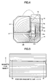
- Fig. 5 shows the magnetic flux distribution inside the magnetic gap G 0 of the internal magnetic circuit according to the embodiment. As can be seen, the magnetic flux density is substantially uniform over the effective length X 0 -X 1 of the magnetic gap G 0 .
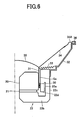
- FIG. 6 is a schematic illustration view of a loudspeaker system incorporating this internal magnetic circuit according to the embodiment.
- a voice coil bobbin 31 is arranged to surround the plate 20 so that the voice coil 30 is positioned inside the magnetic gap G 0 .
- the voice coil 30 has a short winding width so as not to come out of the range of effective length X 0 -X 1 of the magnetic gap G 0 during the vibration.
- the voice coil bobbin 31 is supported on a frame 32 through a damper 33.
- the inner end of a diaphragm 34 is fixedly attached to the periphery of the voice coil bobbin 31, while the outer end of the diaphragm 34 is supported on the periphery of the frame 32 through an edge 34A.
- the reference numerals 35 and 36 represent a center cap and a gasket, respectively.
- the voice coil 30 can cope with large input signals because even a large amplitude vibration stretching over the entire effective length of the magnetic gap G 0 of the voice coil 30 will not cause any nonlinear distortion, since the magnetic flux distribution is uniform over the entire effective length of the magnetic gap G 0 .
- the loudspeaker system is capable of high-quality, high-power output.
Landscapes
- Physics & Mathematics (AREA)
- Engineering & Computer Science (AREA)
- Acoustics & Sound (AREA)
- Signal Processing (AREA)
- Audible-Bandwidth Dynamoelectric Transducers Other Than Pickups (AREA)
Abstract
Description
- The present invention relates to an internal magnetic circuit having a magnet, a yoke, and a plate, and a loudspeaker system incorporating the magnetic circuit.
- Fig. 1 shows one prior art example of a loudspeaker system incorporating an internal magnetic circuit disclosed in Japanese Patent Laid-Open Publication No. Hei 6-261393, and Fig. 2 is an explanatory view showing the internal magnetic circuit. A vertically
magnetized magnet 2 and a plate 1 forming a pole piece are arranged inside a yoke 3 having abottom part 3a and aside part 3b surrounding the plate 1. Themagnet 2 is attached to the bottom face of the plate 1 and to thebottom part 3a of the yoke 3. An air gap or magnetic gap G is formed between the plate 1 and the yoke 3. Themagnet 2, the yoke 3 on the side of one magnetic pole of themagnet 2, the plate 1 on the side of the other magnetic pole of themagnet 2, and the magnetic gap G form an internal magnetic circuit. - A
voice coil bobbin 5 is arranged such as to surround the pillar-like plate 1 which forms the pole piece, so that a voice coil 4 is positioned inside the magnetic gap G. Thevoice coil bobbin 5 is supported on a frame 6 through a damper 7. The inner end of a diaphragm 8 is fixedly attached to the periphery of thevoice coil bobbin 5, while the outer end of the diaphragm 8 is supported on the periphery of the frame 6 through anedge 8A.Reference numerals - It is known that in such a loudspeaker system the winding width of the voice coil 4 relative to the effective length of the magnetic gap G has a close correlation with the distortion caused by the nonlinearity of drive force. Accordingly, a short voice coil design in which the voice coil 4 has a small winding width has been adopted so that even a maximum amplitude of the loudspeaker system does not cause the voice coil 4 to come out of the range of effective length of the magnetic gap G, whereby drive force variations in response to the input signal current are suppressed, and thus nonlinear distortion is prevented.
- This short voice coil design has the effect of preventing nonlinear distortion on condition that the magnetic flux distribution in the magnetic gap G is uniform. In a conventional internal magnetic circuit, however, the magnetic flux density distribution inside the magnetic gap is not necessarily uniform particularly if it has a long effective length.
- Fig. 2 shows the magnetic circuit formed by the
magnet 2, the yoke 3 and plate 1 arranged on the opposite sides of themagnet 2, and the magnetic gap G. As shown, most of the magnetic flux lines form loops leaving from one magnetic pole of themagnet 2, passing through thebottom part 3a andside part 3b of the yoke 3, crossing the magnetic gap G, passing the plate 1, and entering the other magnetic pole of the magnet. The density of these magnetic flux lines tends to be high on the side of shorter loops, i.e., the nearer the loops are to themagnet 2, the higher the density is, and vice versa. - That is, within the effective length X0-X1 of the magnetic gap G, the magnetic flux density is higher on the X0 side, while it is lower on the X1 side. The magnetic flux density decreases in the direction of from X0 to X1 as shown in Fig. 3 within the effective length X0-X1, meaning that the magnetic flux density is not uniform in the direction in which the voice coil 4 moves.
- Therefore, large amplitude vibration of the voice coil 4 located inside the magnetic gap G resulting from a large input signal may lead to the nonlinear distortion of sound signals. This is particularly evident in a loudspeaker system with the aforementioned short voice coil design.
- The present invention has been devised to resolve the above problem, and an object of the present invention is to provide a magnetic circuit having uniform magnetic flux density inside the magnetic gap along the direction of its length, and thereby to provide a loudspeaker system capable of outputting sound with less distortion.
- To achieve the above object, according to a first aspect of the present invention, an internal magnetic circuit includes a magnet, a yoke arranged on one magnetic pole of the magnet, and a plate arranged on the other magnetic pole of the magnet. A magnetic gap is formed between the yoke and plate. In this configuration, a magnetic flux density inside the magnetic gap is made uniform by elongating a magnetic path length of magnetic flux, at a near side to said magnet, extending across said magnetic gap.
- According to a second aspect of the present invention, in the internal magnetic circuit configured as described above, the yoke includes a gap for allowing a magnetic flux loop extending across the magnetic gap to detour, so that the magnetic path length of magnetic flux can be elongated.
- According to a third aspect of the present invention, in the internal magnetic circuit configured as described above, the yoke is made up of a bottom part attached to a bottom face of the magnet, a side part standing on a side of the plate, and a folded-back part which folds downward over the side part such as to face the magnetic gap.
- According to a fourth aspect of the present invention, there is also provided a loudspeaker system incorporating the internal magnetic circuit in any one of the first to third aspects, wherein a voice coil is positioned inside the magnetic gap.
- These and other objects and advantages of the present invention will become clear from the following description with reference to the accompanying drawings, wherein:
- Fig. 1 is an explanatory view showing a conventional loudspeaker system incorporating an internal magnetic circuit;
- Fig. 2 is an explanatory view showing the internal magnetic circuit in the conventional loudspeaker system;
- Fig. 3 is a graph showing the magnetic flux density inside a magnetic gap in the magnetic circuit with the conventional design;
- Fig. 4 is an explanatory view showing an internal magnetic circuit according to one embodiment of the present invention;
- Fig. 5 is a graph showing the magnetic flux density inside the magnetic gap in this magnetic circuit according to the embodiment of the present invention; and
- Fig. 6 is an explanatory view showing a loudspeaker system incorporating the internal magnetic circuit according to the embodiment of the present invention.
- One embodiment of the present invention will be described below with reference to the accompanying drawings. Fig. 4 illustrates an internal magnetic circuit according to the embodiment of the present invention, which includes a
plate 20 forming a pole piece, a verticallymagnetized magnet 21 attached to a bottom face of theplate 20, and ayoke 22 attached to a bottom face of themagnet 21. Between theplate 20 andyoke 22 is formed a magnetic gap G0. - The primary feature of this embodiment is that the magnetic flux density inside the magnetic gap G0 is made uniform by elongating the magnetic path length of part of the magnetic flux crossing the magnetic gap G0.
- More specifically, in this internal magnetic circuit formed by the
magnet 21, theyoke 22 andplate 20 arranged on opposite sides of themagnet 21, and the magnetic gap G0, most of the magnetic flux lines form loops leaving from one magnetic pole of themagnet 21, passing through theyoke 22, crossing the magnetic gap G0, passing through theplate 20, and entering the other magnetic pole of themagnet 21. Therefore, by elongating the magnetic path length of magnetic flux loops R1 crossing the magnetic gap G on the side nearer to themagnet 21, shorter loops are dispersed evenly in the range of the effective length X0-X1, whereby the magnetic flux density inside the magnetic gap G0 is made uniform. - The secondary feature of the embodiment is that the
yoke 22 is formed with agap 22a for allowing the magnetic flux loops crossing the magnetic gap G0 to detour. Thegap 22a is formed opposite the magnetic gap G0 parallel thereto in theyoke 22, so that the magnetic flux loops make a detour around thegap 22a before reaching the magnetic gap G0. Accordingly, there is no concentration of shorter loops in the range of the effective length X0-X1 inside the magnetic gap G0, and the magnetic flux density therein is made uniform. - The third feature of the embodiment is that the
yoke 22 is made up of abottom part 22b which is attached to a bottom face of themagnet 21, aside part 22c standing upright on the side of theplate 20, and a folded-back part 22d which extends from theside part 22c and folds over downwardly to face the magnetic gap G0. With such a construction, thegap 22a can be formed between theside part 22c and folded-back part 22d of theyoke 22, without causing theyoke 22 to take up much space in the magnetic circuit. Thegap 22a thus causes the magnetic flux loops to detour passing through theside part 22c of theyoke 22, so that there is no concentration of shorter loops in the range of the effective length X0-X1, and the magnetic flux density inside the magnetic gap G0 can be made uniform. - Fig. 5 shows the magnetic flux distribution inside the magnetic gap G0 of the internal magnetic circuit according to the embodiment. As can be seen, the magnetic flux density is substantially uniform over the effective length X0-X1 of the magnetic gap G0.
- Fig. 6 is a schematic illustration view of a loudspeaker system incorporating this internal magnetic circuit according to the embodiment. A
voice coil bobbin 31 is arranged to surround theplate 20 so that thevoice coil 30 is positioned inside the magnetic gap G0. Thevoice coil 30 has a short winding width so as not to come out of the range of effective length X0-X1 of the magnetic gap G0 during the vibration. Thevoice coil bobbin 31 is supported on aframe 32 through adamper 33. The inner end of adiaphragm 34 is fixedly attached to the periphery of thevoice coil bobbin 31, while the outer end of thediaphragm 34 is supported on the periphery of theframe 32 through anedge 34A. Thereference numerals - In such a loudspeaker system, the
voice coil 30 can cope with large input signals because even a large amplitude vibration stretching over the entire effective length of the magnetic gap G0 of thevoice coil 30 will not cause any nonlinear distortion, since the magnetic flux distribution is uniform over the entire effective length of the magnetic gap G0. Thus the loudspeaker system is capable of high-quality, high-power output.
Claims (4)
- An internal magnetic circuit, comprising:- a magnet (21) ;- a yoke (22) arranged on one magnetic pole of the magnet (21); and- a plate (20) arranged on the other magnetic pole of the magnet (21), a magnetic gap (Go) being formed between the yoke (22) and the plate (20),- wherein a magnetic flux density inside the magnetic gap (Go) is made uniform by elongating a magnetic path length of the magnetic flux, at a near side to the magnet (21), extending across the magnetic gap (Go)
- The internal magnetic circuit according to claim 1,
wherein the yoke (22) includes a gap (22a) for allowing a magnetic flux loop (R1) extending across the magnetic gap (Go to make a detour so that the magnetic path length of the magnetic flux can be elongated. - The internal magnetic circuit according to claim 1 and 2,
wherein the yoke (22) includes a bottom part (22b) attached to a bottom face of the magnet (21), a side part (22c) standing on a side of the plate, and a folded-back part (22d) folding downward over the side part (22c) such as to face the magnetic gap (Go) - A loudspeaker system incorporating the internal magnetic circuit according to any one of claims 1 to 3,
wherein a voice coil (30) is positioned inside the magnetic gap (Go).
Applications Claiming Priority (2)
| Application Number | Priority Date | Filing Date | Title |
|---|---|---|---|
| JP2002178329A JP4073717B2 (en) | 2002-06-19 | 2002-06-19 | Inner magnet type magnetic circuit and speaker device |
| JP2002178329 | 2002-06-19 |
Publications (1)
| Publication Number | Publication Date |
|---|---|
| EP1377117A1 true EP1377117A1 (en) | 2004-01-02 |
Family
ID=29717483
Family Applications (1)
| Application Number | Title | Priority Date | Filing Date |
|---|---|---|---|
| EP03013872A Withdrawn EP1377117A1 (en) | 2002-06-19 | 2003-06-18 | Internal magnetic circuit and loudspeaker system incorporating the same |
Country Status (3)
| Country | Link |
|---|---|
| US (1) | US7120271B2 (en) |
| EP (1) | EP1377117A1 (en) |
| JP (1) | JP4073717B2 (en) |
Cited By (1)
| Publication number | Priority date | Publication date | Assignee | Title |
|---|---|---|---|---|
| CN104429101A (en) * | 2012-07-06 | 2015-03-18 | 哈曼贝克自动系统制造有限责任公司 | Acoustic transducer assembly |
Families Citing this family (6)
| Publication number | Priority date | Publication date | Assignee | Title |
|---|---|---|---|---|
| JP3752674B2 (en) * | 2002-08-28 | 2006-03-08 | ミネベア株式会社 | Magnetic circuit for speakers |
| JP2009171352A (en) * | 2008-01-17 | 2009-07-30 | Kenwood Corp | Speaker unit |
| KR101363518B1 (en) | 2012-05-08 | 2014-02-17 | 주식회사 비에스이 | Improved electro-magnetic circuit and speaker using the same |
| US8855356B1 (en) * | 2012-12-18 | 2014-10-07 | Skullcandy, Inc. | Dual ring magnet apparatus |
| WO2014134711A1 (en) * | 2013-03-06 | 2014-09-12 | Sentient Magnetics, Inc. | Acoustic transducer assembly |
| US9438999B2 (en) * | 2013-03-06 | 2016-09-06 | Harman Becker Gepkocsirendszer Gyarto Korlatolt Felelossegu Tarsasag | Acoustic transducer assembly |
Citations (3)
| Publication number | Priority date | Publication date | Assignee | Title |
|---|---|---|---|---|
| JPH06261393A (en) * | 1993-03-09 | 1994-09-16 | Matsushita Electric Ind Co Ltd | Speaker |
| JPH07170598A (en) * | 1993-12-15 | 1995-07-04 | Matsushita Electric Ind Co Ltd | Speaker |
| US20020044671A1 (en) * | 2000-06-26 | 2002-04-18 | Katsuya Shimomura | Loudspeaker |
Family Cites Families (4)
| Publication number | Priority date | Publication date | Assignee | Title |
|---|---|---|---|---|
| JP3985987B2 (en) * | 1999-09-27 | 2007-10-03 | パイオニア株式会社 | Speaker device and cooling device for speaker device |
| US6611606B2 (en) * | 2000-06-27 | 2003-08-26 | Godehard A. Guenther | Compact high performance speaker |
| US6671385B2 (en) * | 2000-08-24 | 2003-12-30 | Matsushita Electric Industrial Co., Ltd. | Speaker and magnetic circuit used for the speaker |
| US7039213B2 (en) * | 2002-01-16 | 2006-05-02 | Hyre David E | Speaker driver |
-
2002
- 2002-06-19 JP JP2002178329A patent/JP4073717B2/en not_active Expired - Fee Related
-
2003
- 2003-06-13 US US10/460,649 patent/US7120271B2/en not_active Expired - Fee Related
- 2003-06-18 EP EP03013872A patent/EP1377117A1/en not_active Withdrawn
Patent Citations (3)
| Publication number | Priority date | Publication date | Assignee | Title |
|---|---|---|---|---|
| JPH06261393A (en) * | 1993-03-09 | 1994-09-16 | Matsushita Electric Ind Co Ltd | Speaker |
| JPH07170598A (en) * | 1993-12-15 | 1995-07-04 | Matsushita Electric Ind Co Ltd | Speaker |
| US20020044671A1 (en) * | 2000-06-26 | 2002-04-18 | Katsuya Shimomura | Loudspeaker |
Non-Patent Citations (2)
| Title |
|---|
| PATENT ABSTRACTS OF JAPAN vol. 018, no. 667 (E - 1645) 15 December 1994 (1994-12-15) * |
| PATENT ABSTRACTS OF JAPAN vol. 1995, no. 10 30 November 1995 (1995-11-30) * |
Cited By (3)
| Publication number | Priority date | Publication date | Assignee | Title |
|---|---|---|---|---|
| CN104429101A (en) * | 2012-07-06 | 2015-03-18 | 哈曼贝克自动系统制造有限责任公司 | Acoustic transducer assembly |
| CN104429101B (en) * | 2012-07-06 | 2018-02-27 | 哈曼贝克自动系统制造有限责任公司 | Sound transducer assembly |
| US9936299B2 (en) | 2012-07-06 | 2018-04-03 | Harman Becker Gepkocsirendszer Gyarto Korlatolt Felelossegu Tarsasag | Acoustic transducer assembly |
Also Published As
| Publication number | Publication date |
|---|---|
| JP4073717B2 (en) | 2008-04-09 |
| US7120271B2 (en) | 2006-10-10 |
| JP2004023616A (en) | 2004-01-22 |
| US20040005075A1 (en) | 2004-01-08 |
Similar Documents
| Publication | Publication Date | Title |
|---|---|---|
| US10728672B2 (en) | Sound converter | |
| US9479873B2 (en) | Speaker apparatus | |
| CN1620193B (en) | speaker equipment | |
| US7120271B2 (en) | Internal magnetic circuit and loudspeaker system incorporating the same | |
| US20080025552A1 (en) | Magnetic circuit for speaker device and speaker device | |
| US6590990B2 (en) | Speaker apparatus | |
| US9247350B2 (en) | Acoustic transducer assembly | |
| JP4814361B2 (en) | Speaker unit | |
| CN104284282B (en) | A kind of improvement dynamic iron unit is low, magnetic driving mechanism of high frequency performance | |
| US20060285705A1 (en) | Coaxial speaker | |
| JP3185469U (en) | Speaker | |
| JP3598423B2 (en) | Linear voice coil for dual gap | |
| KR19990041872A (en) | Speaker structure with double voice coil | |
| JPH0733518Y2 (en) | Speaker | |
| JP3733666B2 (en) | Speaker device | |
| KR101971517B1 (en) | High power microspeaker with sub-diaphragm | |
| KR200314357Y1 (en) | Speaker for preventing leakage flux | |
| KR101481650B1 (en) | Microspeaker with improved vibration module | |
| JP4165297B2 (en) | Speaker | |
| JP5524726B2 (en) | Speaker unit | |
| KR20250132213A (en) | The Speaker | |
| KR20040069669A (en) | Leakage magnetic flux decrease speaker | |
| KR970003652Y1 (en) | A speaker for high voltage level | |
| KR200279585Y1 (en) | Speaker | |
| JP2000278792A (en) | Speaker and speaker device |
Legal Events
| Date | Code | Title | Description |
|---|---|---|---|
| PUAI | Public reference made under article 153(3) epc to a published international application that has entered the european phase |
Free format text: ORIGINAL CODE: 0009012 |
|
| AK | Designated contracting states |
Kind code of ref document: A1 Designated state(s): AT BE BG CH CY CZ DE DK EE ES FI FR GB GR HU IE IT LI LU MC NL PT RO SE SI SK TR |
|
| AX | Request for extension of the european patent |
Extension state: AL LT LV MK |
|
| 17P | Request for examination filed |
Effective date: 20040415 |
|
| AKX | Designation fees paid |
Designated state(s): DE FR GB |
|
| 17Q | First examination report despatched |
Effective date: 20050602 |
|
| RBV | Designated contracting states (corrected) |
Designated state(s): DE FR GB |
|
| GRAP | Despatch of communication of intention to grant a patent |
Free format text: ORIGINAL CODE: EPIDOSNIGR1 |
|
| STAA | Information on the status of an ep patent application or granted ep patent |
Free format text: STATUS: THE APPLICATION HAS BEEN WITHDRAWN |
|
| 18W | Application withdrawn |
Effective date: 20071113 |