EP1376974A1 - Method and apparatus for packet header compression - Google Patents
Method and apparatus for packet header compression Download PDFInfo
- Publication number
- EP1376974A1 EP1376974A1 EP02360164A EP02360164A EP1376974A1 EP 1376974 A1 EP1376974 A1 EP 1376974A1 EP 02360164 A EP02360164 A EP 02360164A EP 02360164 A EP02360164 A EP 02360164A EP 1376974 A1 EP1376974 A1 EP 1376974A1
- Authority
- EP
- European Patent Office
- Prior art keywords
- value
- compressed
- wraparound
- data packets
- interval
- Prior art date
- Legal status (The legal status is an assumption and is not a legal conclusion. Google has not performed a legal analysis and makes no representation as to the accuracy of the status listed.)
- Granted
Links
Images


Classifications
-
- H—ELECTRICITY
- H03—ELECTRONIC CIRCUITRY
- H03M—CODING; DECODING; CODE CONVERSION IN GENERAL
- H03M7/00—Conversion of a code where information is represented by a given sequence or number of digits to a code where the same, similar or subset of information is represented by a different sequence or number of digits
- H03M7/30—Compression; Expansion; Suppression of unnecessary data, e.g. redundancy reduction
-
- H—ELECTRICITY
- H04—ELECTRIC COMMUNICATION TECHNIQUE
- H04L—TRANSMISSION OF DIGITAL INFORMATION, e.g. TELEGRAPHIC COMMUNICATION
- H04L69/00—Network arrangements, protocols or services independent of the application payload and not provided for in the other groups of this subclass
- H04L69/04—Protocols for data compression, e.g. ROHC
-
- H—ELECTRICITY
- H04—ELECTRIC COMMUNICATION TECHNIQUE
- H04L—TRANSMISSION OF DIGITAL INFORMATION, e.g. TELEGRAPHIC COMMUNICATION
- H04L69/00—Network arrangements, protocols or services independent of the application payload and not provided for in the other groups of this subclass
- H04L69/22—Parsing or analysis of headers
Definitions
- the present invention relates to a method for transmitting data packets comprising at least one field containing a compressed value.
- IP multimedia packets, or similar data entities comprise usually a long header which should be compressed for transmission on a radio interface for spectrum efficiency purpose. Redundancy between the header of successive packets is used by the compression mechanism to obtain an efficient compression rate. This redundancy extracted from previous transmitted resp. received packets is stored in a context at the transmitter's compression means resp. at the receiver's decompression means. The context should be updated accordingly in order for the mechanism to function error free. Moreover a robust header compression scheme needs mechanisms for avoiding context inconsistencies.
- RFC 3095 from IETF discloses a robust header compression. This header compression is possible due to the fact that there is much redundancy between header field values within consecutive data packets.
- a compression method called Least Significant Bit encoding works as follows: the k least significant bits of a field value are transmitted instead of the original value. After receiving the k bits, the decompressor derives the original value using a previously received value as reference noted v_ref. The scheme is guaranteed to be correct if the compressor and the decompressor each use interpretation intervals in which:
- TS time stamp field
- TS_STRIDE 160 for 8khz sample rate and 20 ms packet duration
- TS/TS_STRIDE In order to reduce the size of the TS field, only TS/TS_STRIDE is compressed and transmitted to the receiver.
- the range of TS/TS_STRIDE is as a consequence 0 to 26843545 if the range for TS is [0, 0xFFFF] (TS usually coded with 32 bits).
- TS/TS_STRIDE jumps from 26843545 to 0.
- the interpretation interval at wraparound comprises more than one single value having as k least significant bits the k received bits.
- 26843536 ...01 10 01 00 00 (v_ref)
- 26843537 ...01 10 01 00 01 26843538 ...01 10 0 1 00 10 ... 26843545 ...01 10 01 10 01 0 ...00 00 00 00 00 ... 18 ...00 00 0 1 00 10 ... 21 ...00 00 01 01 01 (v_ref+2 k -1).
- a solution proposed by RFC 3095 consists in appending at the compressor in case of wraparound a sufficient number, noted b, of "0" to be able to discriminate at the decompressor between several possible values.
- b a sufficient number
- the transmitted compressed value comprises then k+b bits, b being the number of additional bits required to disambiguate the received value and k being the number of compressed bits when no wraparound happens.
- a particular object of the present invention is to provide a method for compressing a value contained in a data packet where the overhead added in case of wraparound is reduced compared to prior art methods.
- Another object of the invention is to provide a transmitter and a receiver both adapted to perform such a method.
- one additional bit (1 bit) is appended to the compressed value (k bits), said additional bit univocally indicating the relative position of said value to be compressed to said wraparound boundary.
- the method according to the present invention presents the advantage of providing a higher compression ratio for the compressed field.
- a further advantageous feature of the method consists in using this method for compressing the time stamp field of a real time protocol data packet.
- Transmitter 11 comprises means 111 for generating a data packet comprising a header H and payload data D.
- Transmitter 11 further comprises a compressor 112 dedicated to compress the data packet header H and an antenna 113 for transmitting the compressed data packet comprising a compressed header CH and payload data D over an air interface to receiver 12.
- Receiver 12 comprises an antenna 123 for receiving compressed data packets, a decompressor 122 for decompressing the compressed header CH and means 121 for further processing decompressed data packets.
- data packets are real time IP datagram according to the real time protocol (RTP) as specified in RFC 1889 from the IETF.
- RTP real time protocol
- data packet type may be used without departing from the scope of the present invention (for example RTP/UDP/IP data packets).
- Header H comprises preferably several fields (e.g. sequence number, originating and destination address, time stamp for real time protocol and so on).
- Compressor 112 preferably compress each field independently of each other. Alternatively, compressor 112 may only compress predefined fields of the header letting uncompressed the fields changing in an unpredictable way.
- the compression method according to the present invention may be used for all fields in header H or only for some of them.
- the method is only applied to fields for which the variation of the value to be compressed is changing in a limited but not predictable range between two consecutive data packets.
- One of such field is the time stamp (TS) field for the header used to indicate the time stamp at which the data packet has been generated in real time protocols.
- TS time stamp
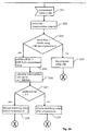
- Figure 2 shows a flow diagram representing the different steps of the method according to the present invention at a transmitter (fig 2a) and at a receiver (fig 2b).
- value 18 will be compressed on five bits with 1 00 10. Since 18 is located after the wraparound boundary, a sixth bit equal to 1 will be appended as most significant bit.
- the compressed value will comprise the six following bits 11 00 10.
- the additional bit may be 1 for values located before the wraparound and 0 for values located after.
- compressor an decompressor use the same rule for determining the meaning of the additional bit.
- the additional bit is appended as most significant bit to the compressed value.
- the additional bit may be appended as least significant bit of the compressed value.
- decompressor 122 At receiver 12 following steps are performed by decompressor 122.
- the present invention also addresses a transmitter comprising means for performing steps 211 to 217 described in figure 2a as well as a receiver comprising means for performing steps 221 to 229 described in figure 2b.
Landscapes
- Engineering & Computer Science (AREA)
- Theoretical Computer Science (AREA)
- Computer Security & Cryptography (AREA)
- Computer Networks & Wireless Communication (AREA)
- Signal Processing (AREA)
- Compression, Expansion, Code Conversion, And Decoders (AREA)
- Data Exchanges In Wide-Area Networks (AREA)
- Compression Or Coding Systems Of Tv Signals (AREA)
Abstract
Description
| 26843536 | ...01 10 01 00 00 (v_ref) |
| 26843537 | ...01 10 01 00 01 |
| 26843538 | ...01 10 0 1 00 10 |
| ... | |
| 26843545 | ...01 10 01 10 01 |
| 0 | ...00 00 00 00 00 |
| ... | |
| 18 | ...00 00 0 1 00 10 |
| ... | |
| 21 | ...00 00 01 01 01 (v_ref+2k-1). |
- Figure 1 shows a system comprising a transmitter and a receiver where the method according to the present invention can be applied;
- Figure 2 shows a flow diagram representing the different steps of the method according to the present invention at a transmitter (fig 2a) and at a receiver (fig 2b).
- At
step 211 thecompressor 112 receives a value to compress. The compressed value will be stored in a field for compressed header CH. - At
step 212, the compressor calculates an interpretation interval as if it would compress the value using the Least Significant Bit compression mechanism or one of its variant as presented in RFC 3095. - At
step 213, the compressor checks if the interpretation interval comprises a wraparound boundary (e.g. wraparound boundary=26853545). - If not, the compression is continued using the usual compression algorithm.(step 214)
- Step 215 consists in generating a compressed value comprising k bits according to the usual compression algorithm. It is to be noted that this compressed value does not univocally represent a value of the interpretation interval because of wraparound. On the contrary, two possible values of the interpretation interval could match the compressed value if using the LBS compression mechanism without modification.
- Step 216 consists in checking if the value to compress is located before or after the wraparound. If the wraparound happens at value N, values belonging to the interval ]N/2, N[ are deemed to be located before the wraparound while values belonging to interval [0, N/2] are deemed to be located after the wraparound.
- Step 217 consists in appending to the compressed value an additional bit equal to 0 if the value to compress is located before the wraparound.
- Step 218 consists in appending to the compressed value an additional bit equal to 1 if the value to compress is located after the wraparound.
- Step 221 consists in receiving at decompressor 122 a compressed value consisting in m bits.
- Step 222 consists in calculating the interpretation interval as a function of m and the reference value stored at the decompressor.
- Step 223 consists in detecting if only one value of the interpretation interval matches the received m bit compressed value.
- If only one value matches,
step 224 consists in decompressing the compressed value according to the usual decompression algorithm (e.g. LBS encoding). - If more than one value matches, steps 225 and following will be executed.
- Step 225 consists in extracting the most significant bit from the m bit compressed value and storing it as additional bit for further processing.
- Step 226 consists in calculating a second interpretation interval as a function of m-1 and the reference value stored at the decompressor.
- Step 227 consists in checking if the additional bit equal 0.
- If additional bit equals 0
step 228 is performedelse step 229 is performed. - Step 228 consists in selecting as decompressed value the only matching value of the second interpretation interval which is located before the wraparound.
- Step 229 consists in selecting as decompressed value the only matching value which is located after the wraparound.
Claims (9)
- Method for transmitting data packets, said data packets comprising a field (CF) containing a compressed value, said compressed value representing a value evolving between two consecutive data packets and being comprised in a predefined interval, herein called interpretation interval, said method comprising the steps of:if the distance between said value to be compressed and a predefined wraparound boundary is lower than a predefined threshold value, appending an additional bit to said compressed value, said additional bit univocally indicating the relative position of said value to be compressed to said wraparound boundary.at a receiver (12), computing a first interpretation interval in accordance with all received bits of said compressed value;signalling a wraparound if more than one value of said first interpretation interval matches the received compressed value;upon signalling of a wraparound, computing a second interpretation interval in accordance with all received bits of said compressed value except said additional bit;disambiguating the decompressed value in said second interpretation interval using said additional bit.
- Method according to claim 1, wherein the variation of said value to be compressed between two successive data packets is changing in a limited range.
- Method according to claim 2, wherein said value to be compressed represents the timestamp (TS) value used in real time communication protocols.
- Method according to claim 3, wherein said timestamp value is obtained byTS_SCALED being equal to said value to be compressed.TS_STRIDE being a predefined unit.TS_OFFSET being an offset between the time scale at the transmitter and at the receiver.
- Method according to claim 1, wherein said compressor calculates a reference value depending on values to be compressed in at least one previous data packet, said first and second interpretation interval depending on said reference value and on the number of bits of said compressed value.
- Method according to claim1, wherein said additional bit is appended as most significant bit to said compressed value.
- Method according to claim 1, used on a radio link of a wireless communication network.
- Transmitter (11) for transmitting data packets, preferably on a radio link, to a receiver, said data packets comprising a field (CF) containing a compressed value, said compressed value representing a value evolving between two consecutive data packets and being comprised in a predefined interval, herein called interpretation interval, said transmitter comprising compressing means(112) for said value , said compressing means (112) comprising:means for detecting if the distance between said value to be compressed and a predefined wraparound boundary is lower than a predefined threshold value;means for appending an additional bit to said encoded value, said additional bit univocally indicating the relative position of said value to be compressed to said wraparound boundary.
- Receiver (12) for receiving data packets, preferably from a radio link, said data packets comprising a field (CF) containing a compressed value, said compressed value representing a value evolving between two consecutive data packets and comprised in an interval of interpretation, said receiver (12) comprising means (122) for decompressing said compressed value, said decompressing means (122) comprising:means for computing a first interpretation interval in accordance with all received bits of said compressed value;means for signalling a wraparound if more than one value of said first interpretation interval matches said compressed field;means for computing a second interpretation interval in accordance with all received bits of said compressed value except one predefined bit;means for disambiguating the decompressed value in said second interpretation interval using said predefined bit.
Priority Applications (3)
| Application Number | Priority Date | Filing Date | Title |
|---|---|---|---|
| AT02360164T ATE369687T1 (en) | 2002-06-06 | 2002-06-06 | METHOD AND DEVICE FOR PACKET HEAD COMPRESSION |
| DE60221656T DE60221656T2 (en) | 2002-06-06 | 2002-06-06 | Method and apparatus for packet header compression |
| EP02360164A EP1376974B1 (en) | 2002-06-06 | 2002-06-06 | Method and apparatus for packet header compression |
Applications Claiming Priority (1)
| Application Number | Priority Date | Filing Date | Title |
|---|---|---|---|
| EP02360164A EP1376974B1 (en) | 2002-06-06 | 2002-06-06 | Method and apparatus for packet header compression |
Publications (2)
| Publication Number | Publication Date |
|---|---|
| EP1376974A1 true EP1376974A1 (en) | 2004-01-02 |
| EP1376974B1 EP1376974B1 (en) | 2007-08-08 |
Family
ID=29716964
Family Applications (1)
| Application Number | Title | Priority Date | Filing Date |
|---|---|---|---|
| EP02360164A Expired - Lifetime EP1376974B1 (en) | 2002-06-06 | 2002-06-06 | Method and apparatus for packet header compression |
Country Status (3)
| Country | Link |
|---|---|
| EP (1) | EP1376974B1 (en) |
| AT (1) | ATE369687T1 (en) |
| DE (1) | DE60221656T2 (en) |
Cited By (1)
| Publication number | Priority date | Publication date | Assignee | Title |
|---|---|---|---|---|
| US8810439B1 (en) | 2013-03-01 | 2014-08-19 | Gurulogic Microsystems Oy | Encoder, decoder and method |
Citations (1)
| Publication number | Priority date | Publication date | Assignee | Title |
|---|---|---|---|---|
| US20020038385A1 (en) * | 2000-09-22 | 2002-03-28 | Juha Kalliokulju | Defining context identifier in header field compression |
-
2002
- 2002-06-06 DE DE60221656T patent/DE60221656T2/en not_active Expired - Fee Related
- 2002-06-06 EP EP02360164A patent/EP1376974B1/en not_active Expired - Lifetime
- 2002-06-06 AT AT02360164T patent/ATE369687T1/en not_active IP Right Cessation
Patent Citations (1)
| Publication number | Priority date | Publication date | Assignee | Title |
|---|---|---|---|---|
| US20020038385A1 (en) * | 2000-09-22 | 2002-03-28 | Juha Kalliokulju | Defining context identifier in header field compression |
Non-Patent Citations (1)
| Title |
|---|
| C. BORMANN ET AL: "Request for Comments 3095, Robust header compression (ROHC), framework and four profiles: RTP, UDP, ESP and uncompressed.", ., 2001, XP002220600 * |
Cited By (4)
| Publication number | Priority date | Publication date | Assignee | Title |
|---|---|---|---|---|
| US8810439B1 (en) | 2013-03-01 | 2014-08-19 | Gurulogic Microsystems Oy | Encoder, decoder and method |
| GB2511355A (en) * | 2013-03-01 | 2014-09-03 | Gurulogic Microsystems Oy | Encoder, decoder and method |
| GB2511355B (en) * | 2013-03-01 | 2015-06-03 | Gurulogic Microsystems Oy | Encoder, decoder and method |
| RU2595916C1 (en) * | 2013-03-01 | 2016-08-27 | Гурулоджик Микросистемс Ой | Encoder, decoder and method |
Also Published As
| Publication number | Publication date |
|---|---|
| ATE369687T1 (en) | 2007-08-15 |
| DE60221656T2 (en) | 2008-05-21 |
| DE60221656D1 (en) | 2007-09-20 |
| EP1376974B1 (en) | 2007-08-08 |
Similar Documents
| Publication | Publication Date | Title |
|---|---|---|
| EP1190548B1 (en) | Estimation of time stamps in real-time packet communications | |
| KR100689612B1 (en) | Compressed header field generation method, header compressor and header decompressor | |
| US20020191614A1 (en) | Packet transmitting/receiving apparatus and packet transmission method | |
| USRE44233E1 (en) | Robust header compression in packet communications | |
| US7266118B2 (en) | Packet receiving apparatus and packet transmission method | |
| US7197687B2 (en) | Header compressed packet receiving apparatus and method | |
| EP1788782B1 (en) | Apparatus and method for header decompression | |
| EP1187416B1 (en) | Method and apparatus for transmitting data packets | |
| JP2004505508A (en) | Header compression method for network protocols | |
| WO2003075504A1 (en) | Packet transmitter, packet receiver and packet transmission method | |
| EP1376974B1 (en) | Method and apparatus for packet header compression | |
| US20040165542A1 (en) | Packet transmitter and packet transmitter method | |
| EP1065857A3 (en) | Method for quick identification of special data packets | |
| WO2004036819A1 (en) | Method and device for transmitting and receiving data using packets carrying priority information | |
| JP3638939B2 (en) | Header restoration apparatus and header restoration method | |
| JP3638940B2 (en) | Header restoration apparatus and header restoration method |
Legal Events
| Date | Code | Title | Description |
|---|---|---|---|
| PUAI | Public reference made under article 153(3) epc to a published international application that has entered the european phase |
Free format text: ORIGINAL CODE: 0009012 |
|
| 17P | Request for examination filed |
Effective date: 20021129 |
|
| AK | Designated contracting states |
Kind code of ref document: A1 Designated state(s): AT BE CH CY DE DK ES FI FR GB GR IE IT LI LU MC NL PT SE TR |
|
| AX | Request for extension of the european patent |
Extension state: AL LT LV MK RO SI |
|
| RIN1 | Information on inventor provided before grant (corrected) |
Inventor name: BROUET, JEROME Inventor name: WAUTIER, ARMELLE Inventor name: ANTOINE, JACQUES Inventor name: HUSSON, LIONEL |
|
| AKX | Designation fees paid |
Designated state(s): AT BE CH CY DE DK ES FI FR GB GR IE IT LI LU MC NL PT SE TR |
|
| GRAP | Despatch of communication of intention to grant a patent |
Free format text: ORIGINAL CODE: EPIDOSNIGR1 |
|
| RAP1 | Party data changed (applicant data changed or rights of an application transferred) |
Owner name: ALCATEL LUCENT |
|
| GRAS | Grant fee paid |
Free format text: ORIGINAL CODE: EPIDOSNIGR3 |
|
| GRAA | (expected) grant |
Free format text: ORIGINAL CODE: 0009210 |
|
| AK | Designated contracting states |
Kind code of ref document: B1 Designated state(s): AT BE CH CY DE DK ES FI FR GB GR IE IT LI LU MC NL PT SE TR |
|
| REG | Reference to a national code |
Ref country code: GB Ref legal event code: FG4D |
|
| REG | Reference to a national code |
Ref country code: CH Ref legal event code: EP |
|
| REG | Reference to a national code |
Ref country code: IE Ref legal event code: FG4D |
|
| REF | Corresponds to: |
Ref document number: 60221656 Country of ref document: DE Date of ref document: 20070920 Kind code of ref document: P |
|
| ET | Fr: translation filed | ||
| PG25 | Lapsed in a contracting state [announced via postgrant information from national office to epo] |
Ref country code: NL Free format text: LAPSE BECAUSE OF FAILURE TO SUBMIT A TRANSLATION OF THE DESCRIPTION OR TO PAY THE FEE WITHIN THE PRESCRIBED TIME-LIMIT Effective date: 20070808 Ref country code: FI Free format text: LAPSE BECAUSE OF FAILURE TO SUBMIT A TRANSLATION OF THE DESCRIPTION OR TO PAY THE FEE WITHIN THE PRESCRIBED TIME-LIMIT Effective date: 20070808 Ref country code: ES Free format text: LAPSE BECAUSE OF FAILURE TO SUBMIT A TRANSLATION OF THE DESCRIPTION OR TO PAY THE FEE WITHIN THE PRESCRIBED TIME-LIMIT Effective date: 20071119 |
|
| NLV1 | Nl: lapsed or annulled due to failure to fulfill the requirements of art. 29p and 29m of the patents act | ||
| REG | Reference to a national code |
Ref country code: CH Ref legal event code: PL |
|
| PG25 | Lapsed in a contracting state [announced via postgrant information from national office to epo] |
Ref country code: LI Free format text: LAPSE BECAUSE OF FAILURE TO SUBMIT A TRANSLATION OF THE DESCRIPTION OR TO PAY THE FEE WITHIN THE PRESCRIBED TIME-LIMIT Effective date: 20070808 Ref country code: CH Free format text: LAPSE BECAUSE OF FAILURE TO SUBMIT A TRANSLATION OF THE DESCRIPTION OR TO PAY THE FEE WITHIN THE PRESCRIBED TIME-LIMIT Effective date: 20070808 Ref country code: AT Free format text: LAPSE BECAUSE OF FAILURE TO SUBMIT A TRANSLATION OF THE DESCRIPTION OR TO PAY THE FEE WITHIN THE PRESCRIBED TIME-LIMIT Effective date: 20070808 |
|
| PG25 | Lapsed in a contracting state [announced via postgrant information from national office to epo] |
Ref country code: BE Free format text: LAPSE BECAUSE OF FAILURE TO SUBMIT A TRANSLATION OF THE DESCRIPTION OR TO PAY THE FEE WITHIN THE PRESCRIBED TIME-LIMIT Effective date: 20070808 |
|
| PG25 | Lapsed in a contracting state [announced via postgrant information from national office to epo] |
Ref country code: DK Free format text: LAPSE BECAUSE OF FAILURE TO SUBMIT A TRANSLATION OF THE DESCRIPTION OR TO PAY THE FEE WITHIN THE PRESCRIBED TIME-LIMIT Effective date: 20070808 Ref country code: GR Free format text: LAPSE BECAUSE OF FAILURE TO SUBMIT A TRANSLATION OF THE DESCRIPTION OR TO PAY THE FEE WITHIN THE PRESCRIBED TIME-LIMIT Effective date: 20071109 |
|
| PG25 | Lapsed in a contracting state [announced via postgrant information from national office to epo] |
Ref country code: PT Free format text: LAPSE BECAUSE OF FAILURE TO SUBMIT A TRANSLATION OF THE DESCRIPTION OR TO PAY THE FEE WITHIN THE PRESCRIBED TIME-LIMIT Effective date: 20080108 |
|
| PLBE | No opposition filed within time limit |
Free format text: ORIGINAL CODE: 0009261 |
|
| STAA | Information on the status of an ep patent application or granted ep patent |
Free format text: STATUS: NO OPPOSITION FILED WITHIN TIME LIMIT |
|
| PG25 | Lapsed in a contracting state [announced via postgrant information from national office to epo] |
Ref country code: SE Free format text: LAPSE BECAUSE OF FAILURE TO SUBMIT A TRANSLATION OF THE DESCRIPTION OR TO PAY THE FEE WITHIN THE PRESCRIBED TIME-LIMIT Effective date: 20071108 |
|
| 26N | No opposition filed |
Effective date: 20080509 |
|
| PGFP | Annual fee paid to national office [announced via postgrant information from national office to epo] |
Ref country code: DE Payment date: 20080620 Year of fee payment: 7 |
|
| PGFP | Annual fee paid to national office [announced via postgrant information from national office to epo] |
Ref country code: FR Payment date: 20080613 Year of fee payment: 7 |
|
| PGFP | Annual fee paid to national office [announced via postgrant information from national office to epo] |
Ref country code: GB Payment date: 20080620 Year of fee payment: 7 |
|
| PG25 | Lapsed in a contracting state [announced via postgrant information from national office to epo] |
Ref country code: MC Free format text: LAPSE BECAUSE OF NON-PAYMENT OF DUE FEES Effective date: 20080630 |
|
| PG25 | Lapsed in a contracting state [announced via postgrant information from national office to epo] |
Ref country code: IE Free format text: LAPSE BECAUSE OF NON-PAYMENT OF DUE FEES Effective date: 20080606 |
|
| PG25 | Lapsed in a contracting state [announced via postgrant information from national office to epo] |
Ref country code: CY Free format text: LAPSE BECAUSE OF FAILURE TO SUBMIT A TRANSLATION OF THE DESCRIPTION OR TO PAY THE FEE WITHIN THE PRESCRIBED TIME-LIMIT Effective date: 20070808 |
|
| GBPC | Gb: european patent ceased through non-payment of renewal fee |
Effective date: 20090606 |
|
| REG | Reference to a national code |
Ref country code: FR Ref legal event code: ST Effective date: 20100226 |
|
| PG25 | Lapsed in a contracting state [announced via postgrant information from national office to epo] |
Ref country code: FR Free format text: LAPSE BECAUSE OF NON-PAYMENT OF DUE FEES Effective date: 20090630 |
|
| PG25 | Lapsed in a contracting state [announced via postgrant information from national office to epo] |
Ref country code: GB Free format text: LAPSE BECAUSE OF NON-PAYMENT OF DUE FEES Effective date: 20090606 |
|
| PG25 | Lapsed in a contracting state [announced via postgrant information from national office to epo] |
Ref country code: DE Free format text: LAPSE BECAUSE OF NON-PAYMENT OF DUE FEES Effective date: 20100101 |
|
| PG25 | Lapsed in a contracting state [announced via postgrant information from national office to epo] |
Ref country code: LU Free format text: LAPSE BECAUSE OF NON-PAYMENT OF DUE FEES Effective date: 20080606 |
|
| PG25 | Lapsed in a contracting state [announced via postgrant information from national office to epo] |
Ref country code: TR Free format text: LAPSE BECAUSE OF FAILURE TO SUBMIT A TRANSLATION OF THE DESCRIPTION OR TO PAY THE FEE WITHIN THE PRESCRIBED TIME-LIMIT Effective date: 20070808 |
|
| PG25 | Lapsed in a contracting state [announced via postgrant information from national office to epo] |
Ref country code: IT Free format text: LAPSE BECAUSE OF NON-PAYMENT OF DUE FEES Effective date: 20080630 |
|
| REG | Reference to a national code |
Ref country code: FR Ref legal event code: CA Effective date: 20150521 |
|
| REG | Reference to a national code |
Ref country code: FR Ref legal event code: CA Effective date: 20150521 |