EP1376845A1 - Method and apparatus for controlling the power supplied to a load - Google Patents
Method and apparatus for controlling the power supplied to a load Download PDFInfo
- Publication number
- EP1376845A1 EP1376845A1 EP03076948A EP03076948A EP1376845A1 EP 1376845 A1 EP1376845 A1 EP 1376845A1 EP 03076948 A EP03076948 A EP 03076948A EP 03076948 A EP03076948 A EP 03076948A EP 1376845 A1 EP1376845 A1 EP 1376845A1
- Authority
- EP
- European Patent Office
- Prior art keywords
- load
- power supply
- switch
- control signal
- frequency
- Prior art date
- Legal status (The legal status is an assumption and is not a legal conclusion. Google has not performed a legal analysis and makes no representation as to the accuracy of the status listed.)
- Withdrawn
Links
- 238000000034 method Methods 0.000 title claims description 13
- 239000003990 capacitor Substances 0.000 description 6
- 238000010586 diagram Methods 0.000 description 5
- 230000005855 radiation Effects 0.000 description 2
- 238000011084 recovery Methods 0.000 description 2
Images


Classifications
-
- H—ELECTRICITY
- H02—GENERATION; CONVERSION OR DISTRIBUTION OF ELECTRIC POWER
- H02M—APPARATUS FOR CONVERSION BETWEEN AC AND AC, BETWEEN AC AND DC, OR BETWEEN DC AND DC, AND FOR USE WITH MAINS OR SIMILAR POWER SUPPLY SYSTEMS; CONVERSION OF DC OR AC INPUT POWER INTO SURGE OUTPUT POWER; CONTROL OR REGULATION THEREOF
- H02M7/00—Conversion of AC power input into DC power output; Conversion of DC power input into AC power output
- H02M7/02—Conversion of AC power input into DC power output without possibility of reversal
- H02M7/04—Conversion of AC power input into DC power output without possibility of reversal by static converters
- H02M7/12—Conversion of AC power input into DC power output without possibility of reversal by static converters using discharge tubes with control electrode or semiconductor devices with control electrode
- H02M7/21—Conversion of AC power input into DC power output without possibility of reversal by static converters using discharge tubes with control electrode or semiconductor devices with control electrode using devices of a triode or transistor type requiring continuous application of a control signal
- H02M7/217—Conversion of AC power input into DC power output without possibility of reversal by static converters using discharge tubes with control electrode or semiconductor devices with control electrode using devices of a triode or transistor type requiring continuous application of a control signal using semiconductor devices only
- H02M7/2176—Conversion of AC power input into DC power output without possibility of reversal by static converters using discharge tubes with control electrode or semiconductor devices with control electrode using devices of a triode or transistor type requiring continuous application of a control signal using semiconductor devices only comprising a passive stage to generate a rectified sinusoidal voltage and a controlled switching element in series between such stage and the output
Definitions
- the invention relates to a method for controlling the power supplied from an AC power supply to an ohmic load, the AC power supply providing a sinusoidal output, the method comprising connecting the load to the AC power supply during a part of each period of the sinusoidal output, wherein the power supplied from the AC power supply to the load is varied by varying the duration of said part of each period.
- the invention further relates an apparatus for controlling the power supplied from an AC power supply to an ohmic load, comprising a switch for connecting the load to the AC power supply, and a controller for providing a control signal to the switch.
- US-A-6 114 669 discloses a method and apparatus of this type, wherein the controller operates according to a so-called phasecut control method.
- the switch Within each half period of the AC voltage the switch is closed for connecting the load to AC power supply and at a zero-cross of the AC voltage the switch opens again.
- flicker and interference radiation are reduced by varying the phase angle of the control signal around a phase angle corresponding to the power to be provided.
- a phasecut control method shows the disadvantage that the control steps are relatively large, whereas phase cutting is inaccurate at small phase angles in particular.
- a phasecut control method causes harmonic distortion resulting in a relatively low value of the power factor.
- the invention aims to provide a method and apparatus of the above-mentioned type meeting high requirements regarding harmonic distortion and flicker.
- the method is characterized in that the sinusoidal output is rectified and the rectified output is delivered to a series connection of a first inductor and the load, wherein the load is connected to and disconnected from the AC power supply at a frequency which is at least 500 times higher than the frequency of the AC power supply, wherein the power supplied from the AC power supply to the load is varied by varying the time ratio of connecting/disconnecting the load.
- the apparatus of the invention is characterized by a rectifier bridge having an input and an output, the input being adapted for connection to the AC power supply and the output being connected to a series connection of a first inductor, the load and the switch, wherein the controller provides a control signal with a frequency which is at least 500 times higher than the frequency of the AC power supply, wherein the switch is switched on and off by said control signal, wherein the controller comprises a control element for varying the duty cycle of the control signal.
- the high-frequency distortion caused by the high-frequency switching of the switch can be suppressed in an effective manner by using the ohmic character of the load in advantageous manner in a suppressing circuit with the inductor.
- the significant reduction of harmonic distortion results in a power factor which approximates the desired value 1.
- the high-frequency switching allows a linear control of the time ratio of connecting/disconnecting the load over the complete range 0-100%. The control steps can be very small.
- the apparatus can be designed for a range of output voltages and frequencies of the AC power supply.
- the method and apparatus according to the invention can be used in various applications such as in heat control equipment, light dimmers, and the like.
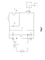
- Fig. 1 shows a schematical circuit diagram of an embodiment of the apparatus of the invention.
- Figs. 2-5 show the current flow in the circuit diagram of Fig. 1 for four different cases during one period of the AC voltage of the AC power supply.
- Figs. 6-9 show diagrams of the AC current of the power supply and the current of the load, respectively, for different duty cycles of the control signal.
- FIG. 1 there is shown a circuit diagram of an embodiment of an apparatus for controlling the power supplied from an AC power supply 1 to an ohmic load 2.
- the AC power supply 1 provides a sinusoidal output voltage and current.
- the apparatus comprises a switch 3 for connecting the load 2 to the power supply 1.
- a FET more particularly a MOSFET
- any other suitable type of switch can be used, for example an IGBT, a transistor, etc.
- a controller 4 provides a control signal to the switch 3 for switching the switch 3 on and off.
- the control signal has a fixed frequency and a variable duty cycle.
- the frequency of the control signal is preferably at least 500 times higher than the frequency of the AC power supply 1.
- the frequency of the control signal is at least 25 kHz.
- the frequency of the control signal is in the range of 50-250 kHz. In this manner the load 2 is connected to and disconnected from the AC power supply 1 a number of times within each period of the AC output voltage.
- the controller 4 comprises a control element 5 for varying the duty cycle of the control signal.
- the duty cycle can be varied from 0 up to 100% thereby varying the power supplied from the power supply 1 to the load 2 from 0 to 100%.
- the control element 5 can be a manually adjustable element or any other suitable element.
- the control element can be part of an electronic controlling circuit which controls the duty cycle in dependence on one or more input signals received from sensors.
- the apparatus comprises a rectifier bridge 6 having an output connected to a series connection of a first inductor 7, the ohmic load 2 and the switch 3.
- the input of the rectifier bridge 6 is connected to the AC power supply 1 through a second inductor 8.
- a freewheeling element made as a capacitor 9 is connected to the output of the rectifier bridge 6 parallel to the series connection of inductor 7, load 2 and switch 3.
- the capacitor 9 could also be connected to the input of the rectifier bridge 6.
- the capacitor 9 is connected to the output of the rectifier bridge as shown in Fig. 1 as in this manner high-frequency paths in the circuit can be reduced thereby reducing EMC radiation.
- the switch 3 is switched off, no unnecessary capacitive current will flow.
- a further freewheeling element 10 is connected parallel to the series connection of the first inductor 7 and the load 2.
- the freewheeling element 10 is a diode of the very fast recovery type.
- the ohmic load 2 receives a rectified sinusoidal voltage having an amplitude which is controlled by the duty cycle of the switch 3.
- the current IL through the load 2 will increase until the switch 3 is switched off.
- the load current IL will be reduced.
- the load 2 will dissipate the energy stored in inductor 7 in the circuit closed through the freewheeling element 10.
- the capacitor 9 operates as a freewheeling element for the inductor 8.
- the third and fourth phases shown in Figs. 4 and 5 correspond to the phases of Fig. 2 and 3, wherein however the voltage V1 of the power supply 1 is negative so that AC current of the power supply will flow in reversed direction through the other two diodes of the rectifier bridge 6.
- the ohmic character of the load 2 is advantageously used in suppressing the harmonic distortions caused by the high frequency switching.
- the harmonic distortion components are located at relatively high frequencies, they can be effectively suppressed by the suppressing circuit formed by the load 2 and the inductor 7.
- the rectifier bridge 6 can be a standard bridge.
- the freewheeling element 10 has to be of a very fast recovery type in order to obtain a high efficiency.
- the frequency of the control signal is preferably in the range of 50-250 kHz.
- the impedance value of the inductors 7 and 8 is preferably in the range of 50-500 ⁇ H and the impedance of the capacitor 9 is preferably in the range of 100 nF up to 2.2 ⁇ F. Good results have been obtained in experiments with an embodiment according to the circuit diagram as shown in Fig.
- the resistance value of the load 2 was 10 ⁇ .
Landscapes
- Engineering & Computer Science (AREA)
- Power Engineering (AREA)
- Rectifiers (AREA)
Abstract
Description
- The invention relates to a method for controlling the power supplied from an AC power supply to an ohmic load, the AC power supply providing a sinusoidal output, the method comprising connecting the load to the AC power supply during a part of each period of the sinusoidal output, wherein the power supplied from the AC power supply to the load is varied by varying the duration of said part of each period. The invention further relates an apparatus for controlling the power supplied from an AC power supply to an ohmic load, comprising a switch for connecting the load to the AC power supply, and a controller for providing a control signal to the switch.
- US-A-6 114 669 discloses a method and apparatus of this type, wherein the controller operates according to a so-called phasecut control method. Within each half period of the AC voltage the switch is closed for connecting the load to AC power supply and at a zero-cross of the AC voltage the switch opens again. In this known apparatus flicker and interference radiation are reduced by varying the phase angle of the control signal around a phase angle corresponding to the power to be provided. Although the known apparatus allows the load to be gradually connected to the AC power supply, a phasecut control method shows the disadvantage that the control steps are relatively large, whereas phase cutting is inaccurate at small phase angles in particular. Moreover, a phasecut control method causes harmonic distortion resulting in a relatively low value of the power factor.
- The invention aims to provide a method and apparatus of the above-mentioned type meeting high requirements regarding harmonic distortion and flicker.
- According to the invention the method is characterized in that the sinusoidal output is rectified and the rectified output is delivered to a series connection of a first inductor and the load, wherein the load is connected to and disconnected from the AC power supply at a frequency which is at least 500 times higher than the frequency of the AC power supply, wherein the power supplied from the AC power supply to the load is varied by varying the time ratio of connecting/disconnecting the load.
- The apparatus of the invention is characterized by a rectifier bridge having an input and an output, the input being adapted for connection to the AC power supply and the output being connected to a series connection of a first inductor, the load and the switch, wherein the controller provides a control signal with a frequency which is at least 500 times higher than the frequency of the AC power supply, wherein the switch is switched on and off by said control signal, wherein the controller comprises a control element for varying the duty cycle of the control signal.
- In this manner a method and apparatus are obtained, wherein the high-frequency distortion caused by the high-frequency switching of the switch can be suppressed in an effective manner by using the ohmic character of the load in advantageous manner in a suppressing circuit with the inductor. The significant reduction of harmonic distortion results in a power factor which approximates the desired
value 1. Further, the high-frequency switching allows a linear control of the time ratio of connecting/disconnecting the load over the complete range 0-100%. The control steps can be very small. The apparatus can be designed for a range of output voltages and frequencies of the AC power supply. - The method and apparatus according to the invention can be used in various applications such as in heat control equipment, light dimmers, and the like.
- The invention will be further explained by reference to the drawings in which an embodiment of the apparatus of the invention is schematically shown.
- Fig. 1 shows a schematical circuit diagram of an embodiment of the apparatus of the invention.
- Figs. 2-5 show the current flow in the circuit diagram of Fig. 1 for four different cases during one period of the AC voltage of the AC power supply.
- Figs. 6-9 show diagrams of the AC current of the power supply and the current of the load, respectively, for different duty cycles of the control signal.
- Referring to Fig. 1 there is shown a circuit diagram of an embodiment of an apparatus for controlling the power supplied from an
AC power supply 1 to anohmic load 2. TheAC power supply 1 provides a sinusoidal output voltage and current. The apparatus comprises aswitch 3 for connecting theload 2 to thepower supply 1. In the embodiment shown a FET, more particularly a MOSFET, is used as theswitch 3. However it will be understood that any other suitable type of switch can be used, for example an IGBT, a transistor, etc. - A
controller 4 provides a control signal to theswitch 3 for switching theswitch 3 on and off. The control signal has a fixed frequency and a variable duty cycle. The frequency of the control signal is preferably at least 500 times higher than the frequency of theAC power supply 1. With a standard frequency of thepower supply 1 of 50 Hz the frequency of the control signal is at least 25 kHz. Preferably, the frequency of the control signal is in the range of 50-250 kHz. In this manner theload 2 is connected to and disconnected from the AC power supply 1 a number of times within each period of the AC output voltage. - The
controller 4 comprises acontrol element 5 for varying the duty cycle of the control signal. The duty cycle can be varied from 0 up to 100% thereby varying the power supplied from thepower supply 1 to theload 2 from 0 to 100%. Thecontrol element 5 can be a manually adjustable element or any other suitable element. As an alternative the control element can be part of an electronic controlling circuit which controls the duty cycle in dependence on one or more input signals received from sensors. - In the embodiment of Fig. 1 the apparatus comprises a rectifier bridge 6 having an output connected to a series connection of a
first inductor 7, theohmic load 2 and theswitch 3. The input of the rectifier bridge 6 is connected to theAC power supply 1 through asecond inductor 8. A freewheeling element made as a capacitor 9 is connected to the output of the rectifier bridge 6 parallel to the series connection ofinductor 7,load 2 andswitch 3. As an alternative the capacitor 9 could also be connected to the input of the rectifier bridge 6. Preferably the capacitor 9 is connected to the output of the rectifier bridge as shown in Fig. 1 as in this manner high-frequency paths in the circuit can be reduced thereby reducing EMC radiation. Moreover when theswitch 3 is switched off, no unnecessary capacitive current will flow. - A
further freewheeling element 10 is connected parallel to the series connection of thefirst inductor 7 and theload 2. In the embodiment shown thefreewheeling element 10 is a diode of the very fast recovery type. - In operation the
ohmic load 2 receives a rectified sinusoidal voltage having an amplitude which is controlled by the duty cycle of theswitch 3. In the phase shown in Fig. 2, wherein voltage V1 of thepower supply 1 is positive and theswitch 3 is closed, the current IL through theload 2 will increase until theswitch 3 is switched off. In the next phase, wherein the voltage V1 is still positive and theswitch 3 is open, the load current IL will be reduced. In this phase theload 2 will dissipate the energy stored ininductor 7 in the circuit closed through thefreewheeling element 10. During this phase the capacitor 9 operates as a freewheeling element for theinductor 8. - The third and fourth phases shown in Figs. 4 and 5 correspond to the phases of Fig. 2 and 3, wherein however the voltage V1 of the
power supply 1 is negative so that AC current of the power supply will flow in reversed direction through the other two diodes of the rectifier bridge 6. - In the circuit of the apparatus described, the ohmic character of the
load 2 is advantageously used in suppressing the harmonic distortions caused by the high frequency switching. As the harmonic distortion components are located at relatively high frequencies, they can be effectively suppressed by the suppressing circuit formed by theload 2 and theinductor 7. - It is noted that the rectifier bridge 6 can be a standard bridge. The
freewheeling element 10 has to be of a very fast recovery type in order to obtain a high efficiency. As indicate above, the frequency of the control signal is preferably in the range of 50-250 kHz. The impedance value of theinductors first inductor 7, an impedance of 500 µH for thesecond inductor 8 and an impedance of 100 nF for capacitor 9. The resistance value of theload 2 was 10 Ω. - It will be understood that the invention is not restricted to embodiments with components having such values and that the embodiment shown can be varied in a number of ways within the scope of the following claims.
Claims (6)
- Method for controlling the power supplied from an AC power supply to an ohmic load, the AC power supply providing a sinusoidal output, the method comprising connecting the load to the AC power supply during a part of each period of the sinusoidal output, wherein the power supplied from the AC power supply to the load is varied by varying the duration of said part of each period, characterized in that the sinusoidal output is rectified and the rectified output is delivered to a series connection of a first inductor and the load, wherein the load is connected to and disconnected from the AC power supply at a frequency which is at least 500 times higher than the frequency of the AC power supply, wherein the power supplied from the AC power supply to the load is varied by varying the time ratio of connecting/disconnecting the load.
- Apparatus for controlling the power supplied from an AC power supply to an ohmic load, comprising a switch for connecting the load to the AC power supply, a controller for providing a control signal to the switch, characterized by a rectifier bridge having an input and an output, the input being adapted for connection to the AC power supply and the output being connected to a series connection of a first inductor, the load and the switch, wherein the controller provides a control signal with a frequency which is at least 500 times higher than the frequency of the AC power supply, wherein the switch is switched on and off by said control signal, wherein the controller comprises a control element for varying the duty cycle of the control signal.
- Apparatus according to claim 2, wherein a freewheeling element is connected parallel to the series connection of the first inductor and the load.
- Apparatus according to claim 2 or 3, wherein a second inductor is series connected to the input of the rectifier bridge.
- Apparatus according to any one of the preceding claims, wherein a freewheeling element is connected parallel to the rectifier bridge, preferably to the output of the bridge.
- Apparatus according to any one of the preceding claims, wherein the frequency of the control signal is in the range of 50 up to 250 kHz.
Priority Applications (1)
| Application Number | Priority Date | Filing Date | Title |
|---|---|---|---|
| EP03076948A EP1376845A1 (en) | 2002-06-28 | 2003-06-24 | Method and apparatus for controlling the power supplied to a load |
Applications Claiming Priority (3)
| Application Number | Priority Date | Filing Date | Title |
|---|---|---|---|
| EP02078187 | 2002-06-28 | ||
| EP02078187 | 2002-06-28 | ||
| EP03076948A EP1376845A1 (en) | 2002-06-28 | 2003-06-24 | Method and apparatus for controlling the power supplied to a load |
Publications (1)
| Publication Number | Publication Date |
|---|---|
| EP1376845A1 true EP1376845A1 (en) | 2004-01-02 |
Family
ID=29718292
Family Applications (1)
| Application Number | Title | Priority Date | Filing Date |
|---|---|---|---|
| EP03076948A Withdrawn EP1376845A1 (en) | 2002-06-28 | 2003-06-24 | Method and apparatus for controlling the power supplied to a load |
Country Status (1)
| Country | Link |
|---|---|
| EP (1) | EP1376845A1 (en) |
Citations (4)
| Publication number | Priority date | Publication date | Assignee | Title |
|---|---|---|---|---|
| US5673184A (en) * | 1994-09-01 | 1997-09-30 | Deutsche Thomson-Brandt Gmbh | Switch mode power supply circuit with increased power factor for mains |
| US5740022A (en) * | 1995-08-19 | 1998-04-14 | Toko, Inc. | Power factor improving circuit |
| US5856917A (en) * | 1994-09-05 | 1999-01-05 | Tdk Corporation | Electric power device with improved power factor |
| US6061259A (en) * | 1999-08-30 | 2000-05-09 | Demichele; Glenn | Protected transformerless AC to DC power converter |
-
2003
- 2003-06-24 EP EP03076948A patent/EP1376845A1/en not_active Withdrawn
Patent Citations (4)
| Publication number | Priority date | Publication date | Assignee | Title |
|---|---|---|---|---|
| US5673184A (en) * | 1994-09-01 | 1997-09-30 | Deutsche Thomson-Brandt Gmbh | Switch mode power supply circuit with increased power factor for mains |
| US5856917A (en) * | 1994-09-05 | 1999-01-05 | Tdk Corporation | Electric power device with improved power factor |
| US5740022A (en) * | 1995-08-19 | 1998-04-14 | Toko, Inc. | Power factor improving circuit |
| US6061259A (en) * | 1999-08-30 | 2000-05-09 | Demichele; Glenn | Protected transformerless AC to DC power converter |
Similar Documents
| Publication | Publication Date | Title |
|---|---|---|
| EP2380406B1 (en) | Direct ac-to-dc converter for passive component minimization and universal operation of led arrays | |
| US8339055B2 (en) | Inrush current limiter for an LED driver | |
| KR101001241B1 (en) | AC LED dimmer and dimming method | |
| JP6200810B2 (en) | Lighting power supply circuit with peak current limiter for EMI filter | |
| US9271352B2 (en) | Line ripple compensation for shimmerless LED driver | |
| CN105322777B (en) | power factor correction circuit for power electronic system | |
| AU5233100A (en) | Power supply | |
| US5155430A (en) | Switching power supply with constant or sinusoidal input current and with fixed or variable output voltage | |
| US7015679B2 (en) | Circuit and method for supplying an electrical a.c. load | |
| US6172489B1 (en) | Voltage control system and method | |
| US6909258B2 (en) | Circuit device for driving an AC electric load | |
| US6870748B2 (en) | Method and apparatus for controlling the power supplied to a load | |
| WO2014139399A1 (en) | An electrical load driving apparatus | |
| KR101029874B1 (en) | Ac led dimmer and dimming method thereby | |
| EP1376845A1 (en) | Method and apparatus for controlling the power supplied to a load | |
| KR101367383B1 (en) | Ac led dimmer | |
| CN103874272B (en) | A kind of LED dimming power sources | |
| JP3551987B2 (en) | Class E rectifier to which thinning control method is applied | |
| US20240206021A1 (en) | Method of controlling a switching converter and related switching converter | |
| CN104702132B (en) | A kind of control method and device of switching tube | |
| KR100612596B1 (en) | Light adjuster | |
| CN2935618Y (en) | Electronic control equipment | |
| Bustoni et al. | Bridge-less Power Factor Correction Converter with Adaptive Switching Pulse Enabling Control | |
| EP1998241A1 (en) | Method and apparatus for electrical power conversion |
Legal Events
| Date | Code | Title | Description |
|---|---|---|---|
| PUAI | Public reference made under article 153(3) epc to a published international application that has entered the european phase |
Free format text: ORIGINAL CODE: 0009012 |
|
| AK | Designated contracting states |
Kind code of ref document: A1 Designated state(s): AT BE BG CH CY CZ DE DK EE ES FI FR GB GR HU IE IT LI LU MC NL PT RO SE SI SK TR |
|
| AX | Request for extension of the european patent |
Extension state: AL LT LV MK |
|
| 17P | Request for examination filed |
Effective date: 20040702 |
|
| AKX | Designation fees paid |
Designated state(s): AT BE BG CH CY CZ DE DK EE ES FI FR GB GR HU IE IT LI LU MC NL PT RO SE SI SK TR |
|
| 17Q | First examination report despatched |
Effective date: 20070222 |
|
| STAA | Information on the status of an ep patent application or granted ep patent |
Free format text: STATUS: THE APPLICATION IS DEEMED TO BE WITHDRAWN |
|
| 18D | Application deemed to be withdrawn |
Effective date: 20090804 |