EP1376710A1 - Cell drive type actuator and manufacturing method - Google Patents
Cell drive type actuator and manufacturing method Download PDFInfo
- Publication number
- EP1376710A1 EP1376710A1 EP02714482A EP02714482A EP1376710A1 EP 1376710 A1 EP1376710 A1 EP 1376710A1 EP 02714482 A EP02714482 A EP 02714482A EP 02714482 A EP02714482 A EP 02714482A EP 1376710 A1 EP1376710 A1 EP 1376710A1
- Authority
- EP
- European Patent Office
- Prior art keywords
- piezoelectric
- cell
- type actuator
- cells
- driving type
- Prior art date
- Legal status (The legal status is an assumption and is not a legal conclusion. Google has not performed a legal analysis and makes no representation as to the accuracy of the status listed.)
- Granted
Links
- 238000004519 manufacturing process Methods 0.000 title claims abstract description 52
- 230000005684 electric field Effects 0.000 claims abstract description 31
- 238000000034 method Methods 0.000 claims description 59
- 239000007788 liquid Substances 0.000 claims description 26
- 230000010287 polarization Effects 0.000 claims description 23
- 238000003754 machining Methods 0.000 claims description 21
- 239000000463 material Substances 0.000 claims description 18
- 238000007599 discharging Methods 0.000 claims description 15
- 238000010030 laminating Methods 0.000 claims description 15
- 244000126211 Hericium coralloides Species 0.000 claims description 10
- 239000013078 crystal Substances 0.000 claims description 9
- 230000003746 surface roughness Effects 0.000 claims description 8
- 238000006073 displacement reaction Methods 0.000 abstract description 9
- 238000010438 heat treatment Methods 0.000 abstract description 8
- 210000004027 cell Anatomy 0.000 description 178
- 238000004080 punching Methods 0.000 description 17
- 239000000976 ink Substances 0.000 description 15
- 230000008569 process Effects 0.000 description 15
- 238000010304 firing Methods 0.000 description 12
- 238000003475 lamination Methods 0.000 description 7
- 238000004140 cleaning Methods 0.000 description 5
- 230000008859 change Effects 0.000 description 4
- 230000004913 activation Effects 0.000 description 3
- 238000001035 drying Methods 0.000 description 3
- 230000000694 effects Effects 0.000 description 3
- 238000000227 grinding Methods 0.000 description 3
- 230000003287 optical effect Effects 0.000 description 3
- 238000012545 processing Methods 0.000 description 3
- 238000005476 soldering Methods 0.000 description 3
- 238000000018 DNA microarray Methods 0.000 description 2
- 230000008602 contraction Effects 0.000 description 2
- 238000005520 cutting process Methods 0.000 description 2
- 230000006866 deterioration Effects 0.000 description 2
- 230000002708 enhancing effect Effects 0.000 description 2
- 230000004044 response Effects 0.000 description 2
- 238000000926 separation method Methods 0.000 description 2
- XLYOFNOQVPJJNP-UHFFFAOYSA-N water Substances O XLYOFNOQVPJJNP-UHFFFAOYSA-N 0.000 description 2
- 239000006061 abrasive grain Substances 0.000 description 1
- 230000009471 action Effects 0.000 description 1
- 230000003213 activating effect Effects 0.000 description 1
- 230000004323 axial length Effects 0.000 description 1
- 210000002421 cell wall Anatomy 0.000 description 1
- 238000006243 chemical reaction Methods 0.000 description 1
- 238000000576 coating method Methods 0.000 description 1
- 238000004891 communication Methods 0.000 description 1
- 238000012937 correction Methods 0.000 description 1
- 230000009849 deactivation Effects 0.000 description 1
- 238000013461 design Methods 0.000 description 1
- 238000007606 doctor blade method Methods 0.000 description 1
- 239000011521 glass Substances 0.000 description 1
- 230000006872 improvement Effects 0.000 description 1
- 230000001939 inductive effect Effects 0.000 description 1
- 238000011835 investigation Methods 0.000 description 1
- 239000000155 melt Substances 0.000 description 1
- 238000002156 mixing Methods 0.000 description 1
- 238000012986 modification Methods 0.000 description 1
- 230000004048 modification Effects 0.000 description 1
- 239000002245 particle Substances 0.000 description 1
- 108090000623 proteins and genes Proteins 0.000 description 1
- 230000009467 reduction Effects 0.000 description 1
- 239000004065 semiconductor Substances 0.000 description 1
- 239000007921 spray Substances 0.000 description 1
- 229920001187 thermosetting polymer Polymers 0.000 description 1
- 230000009466 transformation Effects 0.000 description 1
- 230000007704 transition Effects 0.000 description 1
Images



Classifications
-
- B—PERFORMING OPERATIONS; TRANSPORTING
- B41—PRINTING; LINING MACHINES; TYPEWRITERS; STAMPS
- B41J—TYPEWRITERS; SELECTIVE PRINTING MECHANISMS, i.e. MECHANISMS PRINTING OTHERWISE THAN FROM A FORME; CORRECTION OF TYPOGRAPHICAL ERRORS
- B41J2/00—Typewriters or selective printing mechanisms characterised by the printing or marking process for which they are designed
- B41J2/005—Typewriters or selective printing mechanisms characterised by the printing or marking process for which they are designed characterised by bringing liquid or particles selectively into contact with a printing material
- B41J2/01—Ink jet
- B41J2/135—Nozzles
- B41J2/14—Structure thereof only for on-demand ink jet heads
- B41J2/14201—Structure of print heads with piezoelectric elements
- B41J2/14209—Structure of print heads with piezoelectric elements of finger type, chamber walls consisting integrally of piezoelectric material
-
- B—PERFORMING OPERATIONS; TRANSPORTING
- B41—PRINTING; LINING MACHINES; TYPEWRITERS; STAMPS
- B41J—TYPEWRITERS; SELECTIVE PRINTING MECHANISMS, i.e. MECHANISMS PRINTING OTHERWISE THAN FROM A FORME; CORRECTION OF TYPOGRAPHICAL ERRORS
- B41J2/00—Typewriters or selective printing mechanisms characterised by the printing or marking process for which they are designed
- B41J2/005—Typewriters or selective printing mechanisms characterised by the printing or marking process for which they are designed characterised by bringing liquid or particles selectively into contact with a printing material
- B41J2/01—Ink jet
- B41J2/135—Nozzles
- B41J2/16—Production of nozzles
- B41J2/1607—Production of print heads with piezoelectric elements
- B41J2/1609—Production of print heads with piezoelectric elements of finger type, chamber walls consisting integrally of piezoelectric material
-
- B—PERFORMING OPERATIONS; TRANSPORTING
- B41—PRINTING; LINING MACHINES; TYPEWRITERS; STAMPS
- B41J—TYPEWRITERS; SELECTIVE PRINTING MECHANISMS, i.e. MECHANISMS PRINTING OTHERWISE THAN FROM A FORME; CORRECTION OF TYPOGRAPHICAL ERRORS
- B41J2/00—Typewriters or selective printing mechanisms characterised by the printing or marking process for which they are designed
- B41J2/005—Typewriters or selective printing mechanisms characterised by the printing or marking process for which they are designed characterised by bringing liquid or particles selectively into contact with a printing material
- B41J2/01—Ink jet
- B41J2/135—Nozzles
- B41J2/16—Production of nozzles
- B41J2/1621—Manufacturing processes
- B41J2/1623—Manufacturing processes bonding and adhesion
-
- B—PERFORMING OPERATIONS; TRANSPORTING
- B41—PRINTING; LINING MACHINES; TYPEWRITERS; STAMPS
- B41J—TYPEWRITERS; SELECTIVE PRINTING MECHANISMS, i.e. MECHANISMS PRINTING OTHERWISE THAN FROM A FORME; CORRECTION OF TYPOGRAPHICAL ERRORS
- B41J2/00—Typewriters or selective printing mechanisms characterised by the printing or marking process for which they are designed
- B41J2/005—Typewriters or selective printing mechanisms characterised by the printing or marking process for which they are designed characterised by bringing liquid or particles selectively into contact with a printing material
- B41J2/01—Ink jet
- B41J2/135—Nozzles
- B41J2/16—Production of nozzles
- B41J2/1621—Manufacturing processes
- B41J2/1632—Manufacturing processes machining
-
- F—MECHANICAL ENGINEERING; LIGHTING; HEATING; WEAPONS; BLASTING
- F04—POSITIVE - DISPLACEMENT MACHINES FOR LIQUIDS; PUMPS FOR LIQUIDS OR ELASTIC FLUIDS
- F04B—POSITIVE-DISPLACEMENT MACHINES FOR LIQUIDS; PUMPS
- F04B43/00—Machines, pumps, or pumping installations having flexible working members
- F04B43/02—Machines, pumps, or pumping installations having flexible working members having plate-like flexible members, e.g. diaphragms
- F04B43/04—Pumps having electric drive
- F04B43/043—Micropumps
- F04B43/046—Micropumps with piezoelectric drive
-
- H—ELECTRICITY
- H10—SEMICONDUCTOR DEVICES; ELECTRIC SOLID-STATE DEVICES NOT OTHERWISE PROVIDED FOR
- H10N—ELECTRIC SOLID-STATE DEVICES NOT OTHERWISE PROVIDED FOR
- H10N30/00—Piezoelectric or electrostrictive devices
- H10N30/01—Manufacture or treatment
- H10N30/08—Shaping or machining of piezoelectric or electrostrictive bodies
- H10N30/085—Shaping or machining of piezoelectric or electrostrictive bodies by machining
- H10N30/089—Shaping or machining of piezoelectric or electrostrictive bodies by machining by punching
-
- H—ELECTRICITY
- H10—SEMICONDUCTOR DEVICES; ELECTRIC SOLID-STATE DEVICES NOT OTHERWISE PROVIDED FOR
- H10N—ELECTRIC SOLID-STATE DEVICES NOT OTHERWISE PROVIDED FOR
- H10N39/00—Integrated devices, or assemblies of multiple devices, comprising at least one piezoelectric, electrostrictive or magnetostrictive element covered by groups H10N30/00 – H10N35/00
-
- B—PERFORMING OPERATIONS; TRANSPORTING
- B41—PRINTING; LINING MACHINES; TYPEWRITERS; STAMPS
- B41J—TYPEWRITERS; SELECTIVE PRINTING MECHANISMS, i.e. MECHANISMS PRINTING OTHERWISE THAN FROM A FORME; CORRECTION OF TYPOGRAPHICAL ERRORS
- B41J2202/00—Embodiments of or processes related to ink-jet or thermal heads
- B41J2202/01—Embodiments of or processes related to ink-jet heads
- B41J2202/11—Embodiments of or processes related to ink-jet heads characterised by specific geometrical characteristics
-
- H—ELECTRICITY
- H02—GENERATION; CONVERSION OR DISTRIBUTION OF ELECTRIC POWER
- H02N—ELECTRIC MACHINES NOT OTHERWISE PROVIDED FOR
- H02N2/00—Electric machines in general using piezoelectric effect, electrostriction or magnetostriction
- H02N2/02—Electric machines in general using piezoelectric effect, electrostriction or magnetostriction producing linear motion, e.g. actuators; Linear positioners ; Linear motors
- H02N2/021—Electric machines in general using piezoelectric effect, electrostriction or magnetostriction producing linear motion, e.g. actuators; Linear positioners ; Linear motors using intermittent driving, e.g. step motors, piezoleg motors
-
- Y—GENERAL TAGGING OF NEW TECHNOLOGICAL DEVELOPMENTS; GENERAL TAGGING OF CROSS-SECTIONAL TECHNOLOGIES SPANNING OVER SEVERAL SECTIONS OF THE IPC; TECHNICAL SUBJECTS COVERED BY FORMER USPC CROSS-REFERENCE ART COLLECTIONS [XRACs] AND DIGESTS
- Y10—TECHNICAL SUBJECTS COVERED BY FORMER USPC
- Y10T—TECHNICAL SUBJECTS COVERED BY FORMER US CLASSIFICATION
- Y10T156/00—Adhesive bonding and miscellaneous chemical manufacture
- Y10T156/10—Methods of surface bonding and/or assembly therefor
- Y10T156/1052—Methods of surface bonding and/or assembly therefor with cutting, punching, tearing or severing
- Y10T156/1062—Prior to assembly
- Y10T156/1064—Partial cutting [e.g., grooving or incising]
-
- Y—GENERAL TAGGING OF NEW TECHNOLOGICAL DEVELOPMENTS; GENERAL TAGGING OF CROSS-SECTIONAL TECHNOLOGIES SPANNING OVER SEVERAL SECTIONS OF THE IPC; TECHNICAL SUBJECTS COVERED BY FORMER USPC CROSS-REFERENCE ART COLLECTIONS [XRACs] AND DIGESTS
- Y10—TECHNICAL SUBJECTS COVERED BY FORMER USPC
- Y10T—TECHNICAL SUBJECTS COVERED BY FORMER US CLASSIFICATION
- Y10T156/00—Adhesive bonding and miscellaneous chemical manufacture
- Y10T156/10—Methods of surface bonding and/or assembly therefor
- Y10T156/1052—Methods of surface bonding and/or assembly therefor with cutting, punching, tearing or severing
- Y10T156/1062—Prior to assembly
- Y10T156/1074—Separate cutting of separate sheets or webs
Definitions
- the present invention relates to a cell driving type piezoelectriclelectrostrictive actuator. More particularly, it relates to a cell driving type actuator having cells each being formed independently by two piezoelectric/electrostrictive elements, wherein the piezoelectric/electrostrictive elements forming the cells are displaced preferably by a driving electric field applied in the same direction as the polarization field of the piezoelectric elements or in the direction perpendicular to cell wall surfaces of the electrostrictive elements.
- a piezoelectric actuator for instance, a piezoelectric actuator being driven in the shear mode and being used in an ink jet head.
- This is a piezoelectric actuator 71 having such a structure shown in Fig. 7; where a plurality of piezoelectric elements, which is comb teeth 76 and driving parts 74, are formed like teeth of a comb on a base plate 72, and slits 75 between the comb teeth 76 are closed by a cover plate 77 so as to form cells 73 in a generally rectangular parallelepiped.
- An ink head 70 where the cell 73 is used as an ink chamber is constituted by closing the respective openings at the front end of comb teeth in the piezoelectric actuator 71 with a nozzle plate 9 having nozzles 8, and the comb teeth 76 is deformed so as to change the volume of the cell 73 by applying a driving electric field in the direction perpendicular to the direction of the polarization field in comb teeth 76 as the driving parts 74 made of piezoelectric material; thereby the ink filled into the cell 73 can be ejected.
- the driving method for forming the displacement by means of the driving electric field in the direction perpendicular to the polarization field of the piezoelectric elements is called as the shear mode method.
- Such a piezoelectric actuator 71 has been constructed by the procedure shown in Figs. 8(a) - Fig. 8(e).
- a piezoelectric material 86 is provided as in Fig. 8(a), and fired as shown in Fig. 8(b).
- the polarizing treatment is carried out as shown in Fig. 8(c).
- the process of forming fine slits is carried out by using a dicing saw or the like, and the driving parts 74 causing the dislocation due to the driving electric field are formed like teeth of a comb in alignment by interposing a plurality of slits 75 to be a space for storing the ink therein.
- Electrodes 88 are formed on the walls of the slits 75 as shown in Fig. 8(e). Thereafter, as shown in Fig. 7, the cells 73 to be filled with an ink are formed by applying the cover plate 77 formed by a glass plate or the like thereto, and by closing the front ends of the comb teeth 76 with a nozzle plate 9 having nozzles 8.
- Such a manufacturing method has, however, the following problems due to the machining of hard piezoelectric materials.
- the first problem is that it is time-consuming to machine the slits constituting the cells, so that the method is unsuitable for mass production.
- the second problem is that a satisfactory cleaning requires the complex process since the mechanical strength is reduced after the slits are formed while a sufficient cleaning is needed after machining the slits since the resultant is polluted with either free abrasive grains for machining or a liquid for machining. Moreover, it requires inevitably a drying process. Additionally, the cost increases since facilities and the management for cleaning water and exhaust water are required.
- the third problem is that it is difficult to form cells having a high aspect ratio of, for example, more than 10 because the slits constituting the cells to be filled with an ink can not be machined with a width of approximately 60 ⁇ m or less due to the restriction derived from the thickness of the dicing blade used for the machining, and regarding the thickness of a comb tooth, i.e., a driving part, a limited value is automatically determined with respect to the depth since the grinding strength is required for the dicing blade. As a result, it is difficult to form actuator having a high density or having a high strength and a high power.
- the aspect ratio is generally defined by the ratio of the diameter and the axial length in the case of a cylindrical aperture, whereas, in the case of non-cylindrical aperture, for instance, the slit 75 providing a cell made by closing it in subsequent processing, as shown in Fig. 8(d), the aspect ratio is defined by the ratio of the minimum spacing between two facing comb teeth 76, i.e., the width of the slit 75, and the depth of the slit 75.
- a cell of a high aspect ratio means a cell having a slit whose depth is relatively large in comparison with the width.
- the fourth problem is that the process of bonding parts is always required in the subsequent processing when cells having a complex form are produced because only straight and flat slits can be formed due to the machining with a dicing blade. Moreover, the deformation due to the piezoelectric stress extends up to the bounded end of the nozzle plate during operation as a consequence of the straight line machining, and thus it is liable to result in the reduction in the durability of the bonding face.
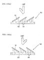
- Fig. 9(a) and Fig. 9(b) are drawings for explaining this fact.
- Fig. 9(a) is a side view of the end face viewed from Q in Fig. 8(d)
- Fig. 9(b) shows an enlarged section of the part N in Fig. 9(a).
- micro cracks and transgranular fractures are often present in the side faces of comb-like driving parts 74 (comb teeth 76) due to the machining.
- it sometimes happens that the intrinsic performance of the material is not attained or that the device itself breaks due to the propagation of micro cracks when the cells are driven.
- the sixth problem subsequent to the fifth problem is that, after firing and carrying out the polarization treatment, the manufacturing process including heating at a temperature higher than the Curie temperature cannot be carried out because the polarization in the piezoelectric material melts away. Therefore, in the case of fixing or wiring the actuator to, e.g., a circuit board, neither soldering by a reflow soldering method or the like nor bonding while heating can be carried out, otherwise, such a process suffers a thermal restriction, and thus throughput is reduced, thereby increasing the cost of manufacturing. Moreover, a machining process inducing heat, such as laser processing or the like, also provides such a restriction.
- the actuator cannot be driven with a high field strength which provides a change in the state of polarization since the driving electric field is applied in the direction perpendicular to that of the polarization field.
- the high driving field strength gradually changes the state of polarization during the period of operation, hence reducing the magnitude of the strain. As a result, the basic performance of the actuator is reduced.
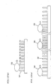
- Fig. 15 shows sectional views of an embodiment of piezoelectric actuator 71 in deactivated and activated states.
- the driving electric field is in OFF state
- the driving parts 74 i.e., the piezoelectric elements are not deformed
- the driving electric field is ON state to the specified driving parts
- the driving parts 74 are deformed.
- an increase in the volume of a cell results in a decrease in the volume of its adjacent cell since the driving part 74 acts as a driving component for the two cells 73.
- the piezoelectric actuator 71 is used as the ink jet head 70 as shown in Fig.
- the ink cannot be ejected simultaneously from adjacent cells. Therefore, at least twice operations are needed in order to spray ink particles to an article to be sprayed in the minimum spacing of the sprayed inks. This is not preferable from the viewpoint of the improvement in the ink discharging rate.
- the present invention has been completed in view of the aforementioned problems and aims to provide a piezoelectric/ electrostrictive actuator to which a high-temperature heating process can be applied, which ensures mass production at a low cost, which can be driven with a high-strength electric field, which has cells not limited to ones each having sectional shape formed by straight lines, i.e., cells including a comb-like piezoelectric/electrostrictive element having the width varied from a recess to the front end of the comb tooth, cells with cell width of 60 ⁇ m or less, and cells having a high aspect ratio, thereby enabling great displacement to be realized with a weak electric field, and also to provide a method for manufacturing the same.
- a cell driving type actuator comprising a plurality of piezoelectric/ electrostrictive elements arranged in alignment like teeth of a comb on a base plate and being a piezoelectric/electrostrictive actuator driven by means of dislocation of piezoelectric/ electrostrictive elements, characterized in that each of cells is formed independently of its adjacent cells by closing respective planes being positioned between two adjacent piezoelectric/ electrostrictive elements and facing the base plate with respective cover plates.
- the polarization field and the driving electric field of said piezoelectric elements are aligned in the same direction.
- the actuator is a piezoelectric/electrostrictive actuator driven by applying a voltage on an electrode film formed on both surfaces of each of adjacent piezoelectric/electrostrictive elements forming said cells and that the dislocation of the piezoelectric/electrostrictive elements is expansion or shrinkage in a vertical direction.
- crystal grains on a surface of the piezoelectric/electrostrictive elements forming said cell are preferably under such a condition that crystal grains having a transgranular fracture is 1% or less. It is preferable that the degree of profile for the surface of said cells is approximately 8 ⁇ m or less. It is preferable that the ratio of the minimum spacing between the adjacent piezoelectric/ electrostrictive elements forming said cell to the minimum spacing between said base plate and said cover plate is approximately 1:2 to 1:40. Further, it is preferable that the ratio of the spacing between each of said cells and the adjacent cells to the minimum spacing between said base plate and said cover plate is approximately 1:2 to 1:40. It is preferable that the minimum spacing between the adjacent piezoelectric/ electrostrictive elements forming said cells is approximately 60 ⁇ m or less and that the spacing between each of said cells and the adjacent cells is approximately 50 ⁇ m or less.
- the surface roughness Rt of the walls of the piezoelectric/electrostrictive elements is approximately 10 ⁇ m or less, said elements facing one another and forming said cell.
- the width of the comb-like piezoelectric/electrostrictive elements preferably varies from a recess to the front end of the comb tooth. It is also preferable that the spacing between the adjacent piezoelectric/electrostrictive elements forming said cell, or the spacing between said cell and the adjacent cell has at least two different values.
- a liquid discharging device wherein piezoelectric elements is utilized, each cell is utilized as a liquid pressurizing chamber, and the piezoelectric elements are displaced by applying a driving electric field thereto in the same direction as the polarization field of the piezoelectric elements so that the piezoelectric elements expand or shrink in a vertical direction, thus deforming said liquid pressurizing chamber, thereby enabling a liquid filled into said liquid pressurizing chamber to be discharged in the direction of the front end of the comb teeth.
- the two methods for manufacturing the cell driving type actuator are further provided as shown below:
- the first manufacturing method is a method for manufacturing, by utilizing a punch and a die, a cell driving type actuator wherein a plurality of piezoelectric/electrostrictive elements are arranged in alignment like teeth of a comb on a base plate; each cell being formed by closing two adjacent piezoelectric/electrostrictive elements disposed on the base plate with a cover plate positioned at a plane facing the base plate in such a manner that said cell is formed independently of its adjacent cells, characterized in that said method comprises the steps of: preparing a plurality of green sheets made of piezoelectric/electrostrictive material, machining slit apertures in all of said green sheets with said punch, and laminating all the green sheets after positioning them, thus forming comb-like piezoelectric/electrostrictive elements.
- the second manufacturing method is a method for manufacturing, by utilizing a punch and a die, a cell driving type actuator wherein a plurality of piezoelectric/electrostrictive elements are arranged in alignment like teeth of a comb on a base plate; each cell being formed by closing two adjacent piezoelectric/electrostrictive elements disposed on the base plate with a cover plate positioned at a plane facing the base plate in such a manner that said cell is formed independently of its adjacent cells, characterized in that said method comprises: a step of preparing a plurality of green sheets made of piezoelectric/electrostrictive material, a first step of machining first slit apertures in a first green sheet with the punch, a second step of moving the first green sheet upwards into tight contact with a stripper in the state of not withdrawing the punch from the first slit apertures, a third step of moving the punch upwards in such a way that the front end of the punch is withdrawn slightly from the lowest part of the first green sheet which was moved
- a cell driving type actuator of the present invention is a piezoelectric/electrostrictive actuator where each of cells formed by closing respective planes being positioned between two adjacent piezoelectric/electrostrictive elements and facing the base plate with respective cover plates is formed independently of its adjacent cells and the cells can be driven independently, and an actuator utilizing a strain induced by an electric field.
- a cell driving type actuator of the present invention is not limited to a piezoelectric actuator or an electrostrictive actuator of a narrow sense, utilizing a piezoelectric effect generating a quantity of strain almost proportional to the applied electric field or an electrostrictive effect generating a quantity of strain almost proportional to a square of the applied electric field and includes an actuator utilizing a phenomenon such as polarization reverse shown in overall ferroelectric materials, antiferroelectric phase - ferroelectric phase transition shown in antiferroelectric materials, or the like. Therefore, whether a polarization treatment is carried out or not is determined suitably on the basis of properties of the material to be used for piezoelectric/electrostrictive elements constituting a piezoelectric/electrostrictive actuator of the present invention.
- the driving parts of the actuator are constituted by piezoelectric elements as a premise, on an occasion that a polarization field is applied.
- the expression to drive an actuator means to drive at least one cell, and to drive a cell means to form a pressurized or a depressurized state in the cell by changing the volume of the cell with deforming the driving parts constituting the cell under application of a driving electric field.
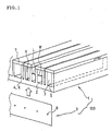
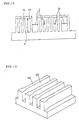
- Fig. 1 is a perspective view showing an embodiment of a cell driving type actuator according to the invention.
- a cell driving type actuator 1 a plurality of piezoelectric/ electrostrictive elements, which are regarded as comb teeth 6 or driving parts 4, are formed like teeth of a comb on a base plate 2, and approximately rectangle-shaped cells 3 are formed by closing the slits 5 between two adjacent comb teeth 6 with cover plates 7.
- the following reference numerals have the following meanings, respectively.
- 1 denotes a cell driving type actuator
- 2, 72 and 162 denote base plates
- 3, 73 and 113 denote cells
- 4, 74, 114, 134 and 164 denote driving parts
- 5, 75 and 125 denote slits
- 6, 76 and 126 denote comb teeth
- 7 and 77 denote cover plates
- 8 denotes a nozzle
- 9 denotes a nozzle plate
- 10 denotes a punch
- 11 denotes a stripper
- 12 denotes a die
- 15 and 25 denote slit apertures
- 16 and 16a ⁇ 16c denote green sheets
- 17 denote a separation tools
- 18, 19 and 88 denote electrodes
- 70 denotes an ink jet head
- 71 denotes a piezoelectric actuator
- 86 denotes a piezoelectric material
- 100 denotes a liquid discharging device
- 130 denotes a product to be transported
- 160 denotes a micro
- a liquid discharging device 100 having driving parts 4 constituted by piezoelectric elements can be constituted by closing openings at the front end of the comb teeth of the cell driving type actuator with a nozzle plate 9 having nozzles 8, wherein the cells 3 are used as liquid pressurizing chambers, and thereby the liquid in the cells 3 is ejected by changing the volume of the cells 3 by applying driving electric field to the comb teeth 6, i.e., the driving parts 4 made of piezoelectric/electrostrictive material, in the same direction as the polarization field so that the comb teeth 6 expand or shrink in a vertical direction.
- the liquid discharging device 100 can be applied, for instance, in the head of an ink jet printer, or in manufacturing DNA chips necessary for mixing liquids in a trace amount and for giving rise to a reaction therein, as well as for analyzing gene structure in the field of biotechnology; or in a micro droplet discharging apparatus which is used in coating processes in semiconductor device production.
- the cell driving type actuator 1 of the present invention is characterized in that the cells 3 formed by closing the surface facing the base plate 2 between two adjacent comb teeth 6 by the cover plates 7 are constituted independently of its adjacent cells 3 unlike the conventional piezoelectric/electrostrictive actuator, in which the base plate, comb teeth and cover plate are unified in one body so as to form a plurality of cells by a common cover plate, or in which one tooth, i.e., a driving part is served, as a driving member for the two cells.
- the present cell driving type actuator 1 has a characteristic point in that the polarization field of the piezoelectric elements constituting the driving part 4 is aligned in the same direction as the driving electric field, on an occasion that piezoelectric elements are utilized.
- Each of cells 3 has a structure in which it is closed by a separate cover plate 7 and formed to be independent of its adjacent cells 3, thereby enabling each cell 3 to be driven completely independently of the other cells 3. Moreover, it is possible to operate the adjacent cells 3 in the same manner.
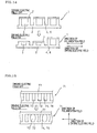
- Fig. 14 shows sectional views showing examples in deactivated and activated states of the cell driving type actuator 1 of the present invention.
- driving parts 4 i.e., piezoelectric/electrostrictive elements do not deform
- the driving electric field is in ON state to a specified driving part 4
- the driving part 4 deforms.
- each of the cells 3 is constructed by two driving parts 4 arranged on the base plate 2 and by the cover plate 7, which closes only a plane facing the base plate 2 between the two driving parts 4.
- the activation of the cell 3 and the activation of the adjacent cells 3 can be carried out independently of each other, without any restriction in the amount of displacement, and it is therefore possible to give rise to the same action for the two adjacent cells 3, as shown in Fig. 14. Accordingly, a less field strength is required to obtain the same magnitude of displacement, compared with the conventional actuator.
- the cell driving type actuator 1 for instance, as the aforementioned liquid discharging device 100, a liquid can be discharged simultaneously from the adjacent cells 3, hence the frequency of activating cells 3 is reduced compared with the conventional cells, thus succeeding in increasing the rate of liquid discharge. More concretely, the cost of production can be greatly reduced compared with the conventional actuator, if the liquid-discharging device 100 is used for the production of DNA chips.
- the polarization field of the piezoelectric elements comprising the driving parts 4 is aligned in the same direction as the driving electric field in the case that piezoelectric elements are utilized, it is unnecessary to produce temporary or dummy electrodes for polarization and to apply the electric field thereto in the manufacturing process, thereby enhancing of the throughput can be intended.
- the piezoelectric actuator e.g., a circuit board with reflow-soldering or thermosetting adhesion, thereby enabling the throughput to be enhanced furthermore, including the process for manufacturing a product to which an actuator is applied, so that the cost of manufacturing can be reduced.
- the actuator is activated by high field strength, the state of polarization remains unchanged, and rather a more preferable state of polarization is provided, and therefore, a higher degree of strain can be stably obtained.
- the actuator can be made more compact, which is preferable as an actuator.
- the comb teeth 6 serving as driving parts 4 change a volume of each of the cells 3 by transformation due to expansion or shrinkage, thereby pressure is generated, it is not necessary to thin the driving parts 4 in order to obtain large displacement. Since this enables the actuator to maintain rigidity, the problem of a dull response is not caused. Thus, a large displacement and a high response can attain simultaneously without causing the conflict therebetween.
- the degree of profile for the cell surface is preferably approximately 8 ⁇ m or less, and the amount of unevenness of the wall surfaces facing each other of the piezoelectric/electrostrictive elements, i.e., the driving parts forming a cell is preferably approximately 10 ⁇ m or less.
- the surface roughness Rt of the wall surfaces facing each other of the piezoelectric/electrostrictive elements, i.e., the driving parts forming a cell is preferably approximately 10 ⁇ m or less.
- the degree of surface profile is specified in Japanese Industrial Standard B0621: "the definition and representation of geometrical deviation".
- the surface profile implies a surface having a functionally predetermined shape, and the degree of profile for the surface is specified by the deviation of the surface contour from the geometrical contour, which is determined by theoretically predetermined dimensions.
- the cell surfaces in the present invention imply the inner wall surfaces of the driving parts forming the aforementioned cells.
- surface roughness in the present invention denotes the surface roughness defined by Japanese Industrial Standard B0601: "surface roughness ⁇ the definition and representation”.
- the surface roughness Rt has the same meaning as the maximum height Rmax defined by the difference in height between the highest point and the lowest point on the surface to be measured.
- the ratio of the minimum spacing between the adjacent piezoelectric/ electrostrictive elements for forming a cell i.e., the cell width W to the minimum spacing between the base plate and the cover plate, i.e., the cell height H, in other words, the aspect ratio W:H of a cell
- the aspect ratio W:H of a cell is preferably substantially 1:2 to 1:40.
- the minimum spacing between the adjacent piezoelectric/electrostrictive elements for forming a cell, i.e., the cell width W is preferably approximately 60 ⁇ m or less. More preferably, the aspect ratio W:H of a cell is 1:10 to 1:25 and the cell width W is approximately 50 ⁇ m or less.
- An actuator fulfilling at least one of these requirements, or, more preferably an actuator fulfilling both requirements, i.e., a thin actuator having a larger height provides a higher power with ease, thereby enabling a higher density to be realized, and making it possible to provide a more compact actuator.
- the ratio of the spacing between a cell and the adjacent cells to the minimum spacing between the base plate and the cover plate is preferably approximately 1:2 to 1:40.
- the spacing between a cell and the adjacent cells i.e., the cell spacing L, is preferably approximately 50 ⁇ m or less. More preferably, the ratio of the spacing between a cell and the adjacent cells to the minimum spacing between the base plate and cover plate is substantially 1:10 to 1:25, and the cell spacing L is approximately 30 ⁇ m or less.
- each cell is independent of the cells adjacent thereto; nevertheless a greater number of cells can be provided, thereby providing a more compact actuator.
- the cell driving type actuator 1 of the invention as shown in Fig. 1 is used as a liquid discharging device 100, a liquid can be simultaneously discharged from three adjacent cells 3, and the liquid can also be discharged with a higher density to an article to be sprayed.
- the cell driving type actuator of the present invention will be described hereinafter.
- Fig. 11 is a sectional view of another embodiment having a cell driving type actuator according to the invention applied to a liquid-discharging device.
- the spacing between adjacent piezoelectric/electrostrictive elements forming a cell i.e., the cell width W
- the spacing between a cell and the adjacent cells i.e., the cell spacing L
- the cell width and the cell spacing L may be determined arbitrarily.
- Fig. 12 is a sectional view of another embodiment of a liquid-discharging device in which the cell driving type actuator according to the invention is used (the cover plate is not shown).
- the width of each comb-like piezoelectric/electrostrictive element i.e., the width of each comb tooth 126, is determined in such a way that the width expands from the recess to the front end of the comb tooth.
- slits 125 forming cells are constructed in such a way that they are narrower at the front end of the comb teeth 126.
- Such a procedure of increasing the width at the front end of the comb teeth provides a smaller stress due to the piezoelectric deformation of the junction to the nozzle plates (shown in Fig.
- Fig. 13(a) and Fig. 13(b) show a transportation apparatus, in which the cell driving type actuator according to the present invention is used (although the cover plates are not shown, the cover plates can be removed).
- driving parts 134 that is, comb teeth
- the driving parts 134 are formed in such a way that the slits have the same width, thus providing transportation at a constant speed;
- the driving parts 134 i.e., the comb teeth, are formed in such a way that the width of a slit varies, hence the speed of transportation changes.
- An electric field is applied to the individual driving parts 134, as shown in Fig.
- a cell driving type actuator can be used as an actuator for changing the direction of a light reflecting mirror; acting as, e.g., an optical switch for switching waveguides for optical signals in an optical communication network, or a projector component, or for a micro-mirror or the like used in a laser unit used in a CD-R/RW apparatus.
- Fig. 10(a) and Fig. 10(b) are sectional views showing an embodiment of a micro-mirror device in which a cell driving type actuator according to the invention is used.
- the direction of the surface of a mirror 161 is altered to reflect light in different directions.
- a micro-mirror device 160 a plurality of driving parts 164, which are piezoelectric/electrostrictive elements, are placed on a base plate 162 and a micro-mirror 161 is mounted onto, for instance, two to four driving parts 164.
- the expansion and contraction of specified driving parts 164, to each of which an electric field is applied, make the direction of the micro-mirror 161 change, thereby changing the direction of the reflected light.
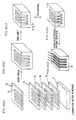
- FIG. 4(a) - Fig. 4(e) An example of the steps in the first method for manufacturing the cell driving type actuator is schematically shown in Fig. 4(a) - Fig. 4(e).
- a punch and a die are used:
- a predetermined number of green sheets 16 made of piezoelectric/electrostrictive material are diecut in a comb-like form with a punch, thus machining slit apertures 15 in each green sheet 16.
- Fig. 4(b) the green sheets are positioned and laminated on a base plate 2, thereby forming the comb-like piezoelectric/electrostrictive elements having a predetermined thickness. Thereafter, the green sheets are fired and unified into one body, for instance, as shown in Fig.
- the method of positioning the green sheets in the lamination process is realized either by successively stacking said green sheets within a frame having the same inner shape which substantially corresponds to the outer shape of the green sheets, or by successively stacking said green sheets, for instance, by passing a guide pin through a predetermined guide hole in each green sheet, so that the positioning is carried out, for instance, under a pressurized state at a high temperature.
- the cover plate can also be formed with a green sheet of the same material, thereby the process of laminating, firing and unifying into one body is similarly applied.
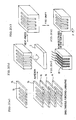
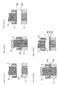
- Fig. 2(a) - Fig. 2(e) are drawings showing an embodiment of the second method for manufacturing a cell driving type actuator according to the invention.
- Fig. 2(a) - Fig. 2(d) schematically show the steps of the process, and Fig. 2(e) schematically shows a finished actuator.
- the second manufacturing method comprises the steps of: first forming slit apertures 15 in a green sheet 16 (hereafter simply denoted by sheet), as in Fig. 2(a), and at the same time, laminating with a method which will be described later; forming comb teeth by laminating the sheets 16; and then completing the lamination together with punching, thereby forming comb-like piezoelectric/electrostrictive elements having a predetermined thickness.
- comb teeth are formed on the base plate 2 made of the sheets prepared for independently, and the sheets laminated are laid on the base plate in Fig. 2(b).
- Fig. 2(c) all the sheets are pressurized under heating, thus bringing them into tight contact with each other.
- Fig. 2(d) all the sheets and the base plate 2 are unified by firing, thereby finishing the driving parts.
- electrodes 6 are formed on the wall of the slits, thus enabling the finished cell driving type actuator to be provided as in Fig. 2(e).
- the green sheets can be formed by conventional means for forming a film, such as the doctor blade method.
- Fig. 6(a) - Fig. 6(e) show the concrete steps of simultaneous punching and laminating method employed in the aforementioned second method.
- a die assembly consisting of a punch 10 and a die 12 is used, and a stripper 11 for laminating the sheets 16 is arranged around the die assembly.
- Fig. 6(a) shows conditions that a first sheet 16a is laid on the die 12 before punching.
- the punch 10 and the stripper 11 fall, thus punching slit apertures in the sheet 16, and then comb teeth are formed (first step).
- a second sheet 16b is provided for punching.
- the first sheet 16a is moved upwards into tight contact with the stripper 11 and is then removed from the die 12 (second step).
- the method for tightly covering the sheet 16 on the stripper 11 can be realized, for instance, by evacuating suction openings formed in the stripper 11.
- the punch 10 and the stripper 11 are moved upwards from the die 12.
- the front end of the punch 10 should not be returned into the slit apertures of the first sheet 16a which simultaneously moves upwards, and in the case of deactivation, it is important to fix the front end at a position slightly withdrawn from the lowest part of the first sheet 16a which simultaneously moves upwards (third step). If the punch 10 is returned to the slit apertures of the first sheet 16a, or is completely inserted into the stripper 11, the slit apertures formed are deformed, because the sheet 16a is soft. Therefore, the flatness of the side face of the comb teeth is reduced when the sheets 16 are laminated to form the comb teeth.
- Fig. 6(d) shows the step of punching the second sheet 16b.
- the second sheet 16b can easily be laid on the die 12 by tightly stacking the first sheet 16a on the stripper 11, so that punching can be performed as in the process of Fig. 6(b), and at the same time, the second sheet is laid on the first sheet 16a (fourth step).
- the second sheet 16b is laid on the first sheet 16a, these sheets are moved upwards (fifth step), and then the third sheet 16c is prepared for punching. In this case, it is also important to keep the sheet at a position slightly withdrawn from the lowest part of the sheet 16 which simultaneously moves upwards (sixth step). After that, by repeating the fourth step to the sixth step, the punching and laminating are repeated till a necessary number of the sheets 16 are obtained.
- Fig. 6(e) shows the state in which the punching has been completed. After the punching and laminating of the necessary number of the sheets 16 are completed, the sheets 16 which are held by the stripper 11 are released, and the punched and laminated sheets 16 can be taken out after removing them from the stripper 16. The removing from the stripper 11 can be securely achieved by applying a separation tool 17 to the lower surface of the stripper 11.
- the aforementioned procedure is that used in the manufacturing method disclosed in Japanese Patent Application No. 2000-280573, and a comb-like multi-slit laminated product having a predetermined thickness can be obtained with this procedure.
- the laminated product is laid on the base plate 2 comprising green sheets of the piezoelectric/ electrostrictive material, and the lamination step is performed under pressure, thereby producing a lamination product capable of handling. Subsequently, the laminated product is fired and unified under conditions suitable for the properties of the sheet, and thereby a cell driving type actuator can be obtained.
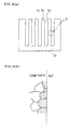
- Fig. 5(a) shows a side view from P in Fig. 2(d)
- Fig. 5(b) schematically shows an enlarged section of part M in the wall surface of slit 5 shown in Fig. 5(a).
- the slit wall surfaces which will later become a cell, are formed with fired surfaces since the comb-like shape is formed before firing.
- micro cracks and transgranular fractures are generated, for example, on the slit wall surfaces.
- crystal grains on a side face of a comb-tooth-like piezo-electric/electrostrictive element forming a cell are under such a condition that crystal grains having a transgranular fracture is 1% or less, which is substantially equal to zero, so that no deterioration in the characteristics occurs, thereby enhancing the durability and reliability.
- fractures at the corners (chipping) hardly occur during machining, and there is no need of the steps of cleaning and drying because no dicing step is employed.
- the accuracy in stacking the green sheets in the second method for manufacturing a cell driving type actuator according to the present invention for example, in the case where 10 green sheets each having a thickness of 50 ⁇ m and a Young's modulus of 39 N/mm 2 are punched to form teeth of a comb to provide a slit width of 50 ⁇ m and a comb tooth width of 30 ⁇ m, and then laminated, the deviation between the respective layers after firing is 4 ⁇ m at maximum and the surface roughness Rt is approximately 7 ⁇ m. As shown in Fig. 5(b), comb teeth having smooth and even side faces can be provided.
- crystal grains of piezoelectric/electrostrictive element does not have a transgranular fracture though they are crystal grains on the surfaces, and crystal grains having a transgranular fracture can be suppressed to be 1% or less.
- the slit width after firing was about 40 ⁇ m due to contraction during firing.
- forming slit apertures in the green sheets with the die and punch simultaneously allows the green sheets to be laminated.
- the punch itself can be used as an axis for adjusting the laminating position of the green sheets, and the deformation of the apertures in the punched slits can be avoided with the aid of the punch.
- no deformation occurs in the slit apertures and the deviation between laminated green sheets is reduced to be 5 ⁇ m or less. Therefore, it is possible to obtain high precision lamination and to form uneven wall surfaces of the slits.
- slits having a high aspect ratio of 10 to 25 can be formed with ease, even for comb tooth having a slit width of less than 70 ⁇ m, and an actuator having excellent properties can be provided.
- the aforementioned second method requires neither tools for moving the sheets nor spaces for stacking the sheets, thereby simplifying the production line and enabling low cost production to be obtained.
- the slit width is substantially the same as the punch machining width in the die assembly when the sheets are punched.
- the combination of thin machined slits and the shrinkage during firing makes it possible to form very small slits having a thickness of 40 ⁇ m or less.
- slits having a shape other than a straight line can easily be formed, so that an optimal shape can be provided in accordance with the application.
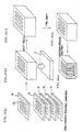
- Figs. 3(a) ⁇ Fig. 3(e) show another embodiment of the second method for manufacturing a cell driving type actuator according to the present invention.
- Fig. 3(a) both forming of slit apertures 25 not having a comb-teeth-like shape and laminating are simultaneously carried out on each sheet 16, thereby providing a laminated product.
- the laminated product is laid on the base plate 2 comprising sheets in Fig. 3(b), and then, all of the layers are, for instance, pressurized under heating, thereby being brought into tight contact with each other as shown in Fig. 3(c), and they are fired and unified into one body as shown in Fig. 3(d).
- the slit apertures punched are elongated, both ends thereof being closed, and are formed in a comb-like shape by cutting them at one end after firing, as shown in Fig. 3(e). Then, after forming electrodes and the like, the manufacturing process is completed.
- the present invention solves the first to eighth problems in the conventional art, and offers a cell driving type actuator and a method for manufacturing the actuator based on the principle of utilizing only a strain caused by an electric field; wherein a heating process at a high temperature can be applied, mass production at low cost is possible; the slit portions may have a cell which has a shape other than a straight one, a width of 60 ⁇ m or less, and a high aspect ratio, the cells can be activated with high electric field strength, and great displacement can be obtained with small electric field strength.
Landscapes
- Engineering & Computer Science (AREA)
- Manufacturing & Machinery (AREA)
- Mechanical Engineering (AREA)
- General Engineering & Computer Science (AREA)
- Particle Formation And Scattering Control In Inkjet Printers (AREA)
- Reciprocating Pumps (AREA)
- Mechanical Light Control Or Optical Switches (AREA)
- Micromachines (AREA)
- General Electrical Machinery Utilizing Piezoelectricity, Electrostriction Or Magnetostriction (AREA)
Abstract
Description
Claims (15)
- A cell driving type actuator comprising a plurality of piezoelectric/electrostrictive elements arranged in alignment like teeth of a comb on a base plate and being a piezoelectric/electrostrictive actuator driven by means of dislocation of piezoelectric/electrostrictive elements,
characterized in that each of cells is formed independently from its adjacent cells by closing respective planes being positioned between two adjacent piezoelectric/ electrostrictive elements and facing the base plate with respective cover plates. - A cell driving type actuator according to claim 1, wherein the piezoelectric elements among said piezoelectric/electro-strictive elements are used for the actuator and the polarization field of said piezoelectric elements and the driving electric field are aligned in the same direction.
- A cell driving type actuator according to claim 1, which is driven by applying a voltage on an electrode film formed on both surfaces of each of adjacent piezoelectric/electrostrictive elements forming said cells,
wherein said dislocation of said piezoelectric/electro-strictive elements is expansion or shrinkage in a vertical direction. - A cell driving type actuator according to any one of claims 1 to 3, wherein crystal grains on a surface of the piezoelectric/ electrostrictive elements forming said cell are under such a condition that crystal grains having a transgranular fracture is 1% or less.
- A cell driving type actuator according to any one of claims 1 to 4, wherein the degree of profile for the surface of said cells is approximately 8 µm or less.
- A cell driving type actuator according to any one of claims 1 to 5, wherein the ratio of the minimum spacing between the adjacent piezoelectric/electrostrictive elements forming said cell to the minimum spacing between said base plate and said cover plate is approximately 1:2 to 1:40.
- A cell driving type actuator according to any one of claims 1 to 6, wherein the ratio of the spacing between each of said cells and the adjacent cells to the minimum spacing between said base plate and said cover plate is approximately 1:2 to 1:40.
- A cell driving type actuator according to any one of claims 1 to 7, wherein the minimum spacing between the adjacent piezoelectric/electrostrictive elements forming said cells is approximately 60 µm or less.
- A cell driving type actuator according to any one of claims 1 to 8, wherein the spacing between each of said cells and the adjacent cells is approximately 50 µm or less.
- A cell driving type actuator according to any one of claims 1 to 9, wherein the surface roughness Rt of the walls of the piezoelectric/electrostrictive elements is approximately 10 µm or less; said elements facing one another and forming said cell.
- A cell driving type actuator according to any one of claims 1 to 10, wherein the width of the comb-like piezoelectric/ electrostrictive elements varies from a recess to the front end of the comb tooth.
- A cell driving type actuator according to any one of claims 1 to 11, wherein the spacing between the adjacent piezoelectric/ electrostrictive elements forming said cell, or the spacing between said cell and the adjacent cell has at least two different values.
- A liquid discharging device using a cell driving type actuator according to any one of claims 2 to 12,
wherein each cell is used as a liquid pressurizing chamber, and said piezoelectric elements are displaced by applying a driving electric field thereto in the same direction as the polarization field of said piezoelectric elements so that the piezoelectric elements expand or shrink in a vertical direction, thus deforming said liquid pressurizing chamber, thereby enabling a liquid filled into said liquid pressurizing chamber to be discharged in the direction of the front end of the comb teeth. - A method for manufacturing, by utilizing a punch and a die, a cell driving type actuator wherein a plurality of piezoelectric/electrostrictive elements are arranged in alignment like teeth of a comb on a base plate; each cell being formed by closing two adjacent piezoelectric/electrostrictive elements disposed on the base plate with a cover plate positioned at a plane facing the base plate in such a manner that said cell is formed independently from its adjacent cells,
characterized in that said method comprises the steps of:preparing a plurality of green sheets made of piezo-electric/electrostrictive material,machining slit apertures in all of said green sheets with said punch, andlaminating all the green sheets after positioning them, thus forming comb-like piezoelectric/electrostrictive elements. - A method for manufacturing, by utilizing a punch and a die, a cell driving type actuator wherein a plurality of piezo-electric/electrostrictive elements are arranged in alignment like teeth of a comb on a base plate; each cell being formed by closing two adjacent piezoelectric/electrostrictive elements disposed on the base plate with a cover plate positioned at a plane facing the base plate in such a manner that said cell is formed independently from its adjacent cells,
characterized in that said method comprises:a step of preparing a plurality of green sheets made of piezoelectric/electrostrictive material,a first step of machining first slit apertures in a first green sheet with the punch,a second step of moving the first green sheet upwards into tight contact with a stripper in the state of not withdrawing the punch from the first slit apertures,a third step of moving the punch upwards in such a way that the front end of the punch is withdrawn slightly from the lowest part of the first green sheet which was moved upwards,a fourth step of machining second slit apertures in a second green sheet with the punch,a fifth step of moving the second green sheet upwards, together with the first green sheet in the state of not withdrawing the punch from the second slit apertures,and a sixth step of moving the punch upwards in such a way that the front end of the punch is withdrawn slightly from the lowest part of the second green sheet which was moved upwards, and thereafter,laminating a plurality of green sheets by repeating the fourth to sixth steps so as to form a comb-like piezoelectric/ electrostrictive elements.
Applications Claiming Priority (5)
| Application Number | Priority Date | Filing Date | Title |
|---|---|---|---|
| JP2001108986 | 2001-04-06 | ||
| JP2001108986 | 2001-04-06 | ||
| JP2001189718 | 2001-06-22 | ||
| JP2001189718 | 2001-06-22 | ||
| PCT/JP2002/003418 WO2002084751A1 (en) | 2001-04-06 | 2002-04-05 | Cell drive type actuator and manufacturing method |
Publications (3)
| Publication Number | Publication Date |
|---|---|
| EP1376710A1 true EP1376710A1 (en) | 2004-01-02 |
| EP1376710A4 EP1376710A4 (en) | 2007-05-30 |
| EP1376710B1 EP1376710B1 (en) | 2012-08-01 |
Family
ID=26613229
Family Applications (1)
| Application Number | Title | Priority Date | Filing Date |
|---|---|---|---|
| EP20020714482 Expired - Lifetime EP1376710B1 (en) | 2001-04-06 | 2002-04-05 | Cell driving type actuator |
Country Status (5)
| Country | Link |
|---|---|
| US (2) | US6699018B2 (en) |
| EP (1) | EP1376710B1 (en) |
| JP (1) | JP4253508B2 (en) |
| DE (1) | DE60230730D1 (en) |
| WO (1) | WO2002084751A1 (en) |
Cited By (2)
| Publication number | Priority date | Publication date | Assignee | Title |
|---|---|---|---|---|
| US7126254B2 (en) | 2003-07-22 | 2006-10-24 | Ngk Insulators, Ltd. | Actuator element and device including the actuator element |
| US7141915B2 (en) | 2003-07-22 | 2006-11-28 | Ngk Insulators, Ltd. | Actuator device |
Families Citing this family (7)
| Publication number | Priority date | Publication date | Assignee | Title |
|---|---|---|---|---|
| US6699018B2 (en) * | 2001-04-06 | 2004-03-02 | Ngk Insulators, Ltd. | Cell driving type micropump member and method for manufacturing the same |
| US6752601B2 (en) * | 2001-04-06 | 2004-06-22 | Ngk Insulators, Ltd. | Micropump |
| US20100254830A1 (en) * | 2006-10-10 | 2010-10-07 | Beebe David J | Magnetically driven micro-pumping method using external rotating stirrer |
| JP4869108B2 (en) * | 2007-03-01 | 2012-02-08 | 株式会社リコー | Liquid ejection head, liquid cartridge, and image forming apparatus |
| US8017409B2 (en) * | 2009-05-29 | 2011-09-13 | Ecolab Usa Inc. | Microflow analytical system |
| WO2011152393A1 (en) * | 2010-06-04 | 2011-12-08 | 日本碍子株式会社 | Method for producing droplet discharge head |
| JP2014091273A (en) * | 2012-11-05 | 2014-05-19 | Sii Printek Inc | Liquid jet head and liquid jet apparatus |
Family Cites Families (33)
| Publication number | Priority date | Publication date | Assignee | Title |
|---|---|---|---|---|
| DE3630206A1 (en) | 1985-09-06 | 1987-03-19 | Fuji Electric Co Ltd | INK JET PRINT HEAD |
| US5210455A (en) * | 1990-07-26 | 1993-05-11 | Ngk Insulators, Ltd. | Piezoelectric/electrostrictive actuator having ceramic substrate having recess defining thin-walled portion |
| US5216631A (en) * | 1990-11-02 | 1993-06-01 | Sliwa Jr John W | Microvibratory memory device |
| JP2855846B2 (en) | 1990-11-22 | 1999-02-10 | ブラザー工業株式会社 | Piezo pump |
| JPH05229129A (en) * | 1992-02-20 | 1993-09-07 | Brother Ind Ltd | Method for manufacturing piezoelectric element for inkjet printer head |
| JPH05251783A (en) * | 1992-03-05 | 1993-09-28 | Nec Corp | Method of manufacturing thickness longitudinal vibration piezoelectric ceramic transformer |
| JPH05303048A (en) | 1992-04-27 | 1993-11-16 | Fujikura Ltd | Optical path switching device |
| US5471231A (en) * | 1992-10-30 | 1995-11-28 | Citizen Watch Co., Ltd. | Ink jet head |
| US5650810A (en) * | 1992-12-03 | 1997-07-22 | Brother Kogyo Kabushiki Kaisha | Ink jet print head having a manifold wall portion and method of producing the same by injection molding |
| SE508435C2 (en) | 1993-02-23 | 1998-10-05 | Erik Stemme | Diaphragm pump type pump |
| JP3147680B2 (en) * | 1994-10-18 | 2001-03-19 | ブラザー工業株式会社 | Ink ejecting apparatus and manufacturing method thereof |
| JPH08156251A (en) * | 1994-12-12 | 1996-06-18 | Brother Ind Ltd | Ink jet device |
| JPH08187848A (en) * | 1995-01-12 | 1996-07-23 | Brother Ind Ltd | Multilayer piezoelectric element and manufacturing method thereof |
| JPH0939244A (en) * | 1995-05-23 | 1997-02-10 | Fujitsu Ltd | Piezoelectric pump |
| US5542821A (en) * | 1995-06-28 | 1996-08-06 | Basf Corporation | Plate-type diaphragm pump and method of use |
| JP3438450B2 (en) | 1995-12-12 | 2003-08-18 | 日立電線株式会社 | Waveguide optical switch and method of manufacturing the same |
| JPH09164676A (en) * | 1995-12-14 | 1997-06-24 | Tec Corp | Head drive for inkjet printer |
| DE69814486T2 (en) * | 1997-01-14 | 2004-04-01 | Nec Corp. | Ink jet recording head with a piezoelectric substrate |
| US6116863A (en) | 1997-05-30 | 2000-09-12 | University Of Cincinnati | Electromagnetically driven microactuated device and method of making the same |
| JPH11254678A (en) | 1998-03-13 | 1999-09-21 | Kyocera Corp | Printing apparatus and manufacturing method thereof |
| JP2873287B1 (en) * | 1998-03-20 | 1999-03-24 | 新潟日本電気株式会社 | Ink jet recording head and method of manufacturing the same |
| JP2000141638A (en) * | 1998-11-10 | 2000-05-23 | Toshiba Tec Corp | Driving method of inkjet head |
| JP2000314381A (en) | 1999-03-03 | 2000-11-14 | Ngk Insulators Ltd | pump |
| US6431212B1 (en) * | 2000-05-24 | 2002-08-13 | Jon W. Hayenga | Valve for use in microfluidic structures |
| US6637102B2 (en) * | 2000-07-19 | 2003-10-28 | Ngk Insulators, Ltd. | Process for producing an industrial member having throughholes of high aspect ratio |
| US6502302B2 (en) * | 2000-07-19 | 2003-01-07 | Ngk Insulators, Ltd. | Process for producing an industrial member having throughholes of high aspect ratio |
| US6699018B2 (en) * | 2001-04-06 | 2004-03-02 | Ngk Insulators, Ltd. | Cell driving type micropump member and method for manufacturing the same |
| US6864620B2 (en) * | 2000-12-22 | 2005-03-08 | Ngk Insulators, Ltd. | Matrix type actuator |
| EP1364793B1 (en) * | 2001-03-01 | 2009-07-15 | Ngk Insulators, Ltd. | Comb piezoelectric actuator, and its manufacturing method |
| US6507682B2 (en) * | 2001-04-06 | 2003-01-14 | Ngk Insulators, Ltd. | Optical switch |
| US6752601B2 (en) * | 2001-04-06 | 2004-06-22 | Ngk Insulators, Ltd. | Micropump |
| JP4172920B2 (en) * | 2001-04-27 | 2008-10-29 | 日本碍子株式会社 | Debris removal method for punching and manufacturing method of punched product |
| JP3930300B2 (en) * | 2001-11-20 | 2007-06-13 | 日本碍子株式会社 | Punching die for simultaneous punching |
-
2001
- 2001-07-06 US US09/900,742 patent/US6699018B2/en not_active Expired - Fee Related
-
2002
- 2002-04-05 JP JP2002581593A patent/JP4253508B2/en not_active Expired - Fee Related
- 2002-04-05 DE DE60230730T patent/DE60230730D1/en not_active Expired - Fee Related
- 2002-04-05 EP EP20020714482 patent/EP1376710B1/en not_active Expired - Lifetime
- 2002-04-05 WO PCT/JP2002/003418 patent/WO2002084751A1/en not_active Ceased
-
2004
- 2004-01-06 US US10/752,199 patent/US7374628B2/en not_active Expired - Fee Related
Cited By (2)
| Publication number | Priority date | Publication date | Assignee | Title |
|---|---|---|---|---|
| US7126254B2 (en) | 2003-07-22 | 2006-10-24 | Ngk Insulators, Ltd. | Actuator element and device including the actuator element |
| US7141915B2 (en) | 2003-07-22 | 2006-11-28 | Ngk Insulators, Ltd. | Actuator device |
Also Published As
| Publication number | Publication date |
|---|---|
| US6699018B2 (en) | 2004-03-02 |
| EP1376710A4 (en) | 2007-05-30 |
| US20040141857A1 (en) | 2004-07-22 |
| US20020146329A1 (en) | 2002-10-10 |
| WO2002084751A1 (en) | 2002-10-24 |
| DE60230730D1 (en) | 2009-02-26 |
| JP4253508B2 (en) | 2009-04-15 |
| JPWO2002084751A1 (en) | 2004-08-05 |
| EP1376710B1 (en) | 2012-08-01 |
| US7374628B2 (en) | 2008-05-20 |
Similar Documents
| Publication | Publication Date | Title |
|---|---|---|
| EP1321294B1 (en) | Piezoelectric ink-jet printhead and method for manufacturing the same | |
| CA1267563A (en) | Impulse ink jet print head and method of making same | |
| US4730197A (en) | Impulse ink jet system | |
| US7161281B2 (en) | Less-dust-generative piezoelectric/electrostrictive device and manufacturing method | |
| KR100339732B1 (en) | Manufacture of ink jet printheads | |
| EP1376710B1 (en) | Cell driving type actuator | |
| EP2047995B1 (en) | Liquid ejection head | |
| EP1645416B1 (en) | Piezoelectric type inkjet printhead and method of manufacturing the same | |
| EP1432048A1 (en) | MATRIX TYPE PIEZOELECTRIC/ELECTROSTRICTIVE DEVICE AND ITS MANUFACTURING METHOD | |
| JP3964193B2 (en) | Matrix type actuator | |
| US6933663B2 (en) | Cell driving type actuator and method for manufacturing the same | |
| JP3693939B2 (en) | Cell-driven micropump member and manufacturing method | |
| JP2005033174A (en) | Cylindrical piezoelectric actuator, cylindrical piezoelectric actuator array, and manufacturing method therefor | |
| JPH1086370A (en) | Ink jet print head and method for forming ink passages thereof | |
| US20020195902A1 (en) | Cell driving type actuator and method for manufacturing the same | |
| US6886224B2 (en) | Method of making an ink jet printer head | |
| EP1389805B1 (en) | Multislit type actuator, inkjet head, and method for manufacturing multislit type actuator | |
| JP2000309096A (en) | Ink jet head and method of manufacturing the same | |
| JP2004223804A (en) | Method of manufacturing inkjet head, inkjet head and inkjet recording apparatus | |
| EP1263059B1 (en) | Matrix actuator | |
| JPH04348949A (en) | Ink droplet jet device | |
| JP2003136705A (en) | Ink jet head and method of manufacturing the same | |
| JPH0994970A (en) | Inkjet head | |
| JP2016124225A (en) | Liquid discharge head and manufacturing method thereof | |
| JP2004249602A (en) | Liquid droplet discharging head and liquid droplet discharging device |
Legal Events
| Date | Code | Title | Description |
|---|---|---|---|
| PUAI | Public reference made under article 153(3) epc to a published international application that has entered the european phase |
Free format text: ORIGINAL CODE: 0009012 |
|
| 17P | Request for examination filed |
Effective date: 20030107 |
|
| AK | Designated contracting states |
Kind code of ref document: A1 Designated state(s): AT BE CH CY DE DK ES FI FR GB GR IE IT LI LU MC NL PT SE TR |
|
| AX | Request for extension of the european patent |
Extension state: AL LT LV MK RO SI |
|
| A4 | Supplementary search report drawn up and despatched |
Effective date: 20070503 |
|
| RIC1 | Information provided on ipc code assigned before grant |
Ipc: H01L 41/09 20060101AFI20070425BHEP Ipc: B41J 2/14 20060101ALI20070425BHEP Ipc: H01L 41/24 20060101ALI20070425BHEP |
|
| 17Q | First examination report despatched |
Effective date: 20070906 |
|
| REG | Reference to a national code |
Ref country code: DE Ref legal event code: R079 Ref document number: 60243417 Country of ref document: DE Free format text: PREVIOUS MAIN CLASS: H01L0041080000 Ipc: H01L0027200000 |
|
| GRAP | Despatch of communication of intention to grant a patent |
Free format text: ORIGINAL CODE: EPIDOSNIGR1 |
|
| RIC1 | Information provided on ipc code assigned before grant |
Ipc: H01L 27/20 20060101AFI20120118BHEP Ipc: H01L 41/24 20060101ALN20120118BHEP Ipc: B41J 2/14 20060101ALI20120118BHEP |
|
| RTI1 | Title (correction) |
Free format text: CELL DRIVING TYPE ACTUATOR |
|
| GRAS | Grant fee paid |
Free format text: ORIGINAL CODE: EPIDOSNIGR3 |
|
| GRAA | (expected) grant |
Free format text: ORIGINAL CODE: 0009210 |
|
| AK | Designated contracting states |
Kind code of ref document: B1 Designated state(s): DE FR GB IT NL |
|
| REG | Reference to a national code |
Ref country code: GB Ref legal event code: FG4D |
|
| REG | Reference to a national code |
Ref country code: DE Ref legal event code: R096 Ref document number: 60243417 Country of ref document: DE Effective date: 20120927 |
|
| REG | Reference to a national code |
Ref country code: NL Ref legal event code: VDEP Effective date: 20120801 |
|
| PG25 | Lapsed in a contracting state [announced via postgrant information from national office to epo] |
Ref country code: NL Free format text: LAPSE BECAUSE OF FAILURE TO SUBMIT A TRANSLATION OF THE DESCRIPTION OR TO PAY THE FEE WITHIN THE PRESCRIBED TIME-LIMIT Effective date: 20120801 |
|
| PG25 | Lapsed in a contracting state [announced via postgrant information from national office to epo] |
Ref country code: IT Free format text: LAPSE BECAUSE OF FAILURE TO SUBMIT A TRANSLATION OF THE DESCRIPTION OR TO PAY THE FEE WITHIN THE PRESCRIBED TIME-LIMIT Effective date: 20120801 |
|
| PLBE | No opposition filed within time limit |
Free format text: ORIGINAL CODE: 0009261 |
|
| STAA | Information on the status of an ep patent application or granted ep patent |
Free format text: STATUS: NO OPPOSITION FILED WITHIN TIME LIMIT |
|
| 26N | No opposition filed |
Effective date: 20130503 |
|
| REG | Reference to a national code |
Ref country code: DE Ref legal event code: R097 Ref document number: 60243417 Country of ref document: DE Effective date: 20130503 |
|
| GBPC | Gb: european patent ceased through non-payment of renewal fee |
Effective date: 20130405 |
|
| PG25 | Lapsed in a contracting state [announced via postgrant information from national office to epo] |
Ref country code: GB Free format text: LAPSE BECAUSE OF NON-PAYMENT OF DUE FEES Effective date: 20130405 |
|
| REG | Reference to a national code |
Ref country code: FR Ref legal event code: ST Effective date: 20131231 |
|
| PG25 | Lapsed in a contracting state [announced via postgrant information from national office to epo] |
Ref country code: FR Free format text: LAPSE BECAUSE OF NON-PAYMENT OF DUE FEES Effective date: 20130430 |
|
| PGFP | Annual fee paid to national office [announced via postgrant information from national office to epo] |
Ref country code: DE Payment date: 20140430 Year of fee payment: 13 |
|
| REG | Reference to a national code |
Ref country code: DE Ref legal event code: R119 Ref document number: 60243417 Country of ref document: DE |
|
| PG25 | Lapsed in a contracting state [announced via postgrant information from national office to epo] |
Ref country code: DE Free format text: LAPSE BECAUSE OF NON-PAYMENT OF DUE FEES Effective date: 20151103 |