EP1376554A2 - Optical recording apparatus with interleaving blank rounds into spiral track - Google Patents
Optical recording apparatus with interleaving blank rounds into spiral track Download PDFInfo
- Publication number
- EP1376554A2 EP1376554A2 EP03014071A EP03014071A EP1376554A2 EP 1376554 A2 EP1376554 A2 EP 1376554A2 EP 03014071 A EP03014071 A EP 03014071A EP 03014071 A EP03014071 A EP 03014071A EP 1376554 A2 EP1376554 A2 EP 1376554A2
- Authority
- EP
- European Patent Office
- Prior art keywords
- recording
- spiral track
- optical
- main beam
- information
- Prior art date
- Legal status (The legal status is an assumption and is not a legal conclusion. Google has not performed a legal analysis and makes no representation as to the accuracy of the status listed.)
- Withdrawn
Links
Images



Classifications
-
- G—PHYSICS
- G11—INFORMATION STORAGE
- G11B—INFORMATION STORAGE BASED ON RELATIVE MOVEMENT BETWEEN RECORD CARRIER AND TRANSDUCER
- G11B7/00—Recording or reproducing by optical means, e.g. recording using a thermal beam of optical radiation by modifying optical properties or the physical structure, reproducing using an optical beam at lower power by sensing optical properties; Record carriers therefor
- G11B7/24—Record carriers characterised by shape, structure or physical properties, or by the selection of the material
- G11B7/24094—Indication parts or information parts for identification
-
- G—PHYSICS
- G11—INFORMATION STORAGE
- G11B—INFORMATION STORAGE BASED ON RELATIVE MOVEMENT BETWEEN RECORD CARRIER AND TRANSDUCER
- G11B7/00—Recording or reproducing by optical means, e.g. recording using a thermal beam of optical radiation by modifying optical properties or the physical structure, reproducing using an optical beam at lower power by sensing optical properties; Record carriers therefor
- G11B7/08—Disposition or mounting of heads or light sources relatively to record carriers
- G11B7/09—Disposition or mounting of heads or light sources relatively to record carriers with provision for moving the light beam or focus plane for the purpose of maintaining alignment of the light beam relative to the record carrier during transducing operation, e.g. to compensate for surface irregularities of the latter or for track following
- G11B7/0901—Disposition or mounting of heads or light sources relatively to record carriers with provision for moving the light beam or focus plane for the purpose of maintaining alignment of the light beam relative to the record carrier during transducing operation, e.g. to compensate for surface irregularities of the latter or for track following for track following only
- G11B7/0903—Multi-beam tracking systems
-
- G—PHYSICS
- G11—INFORMATION STORAGE
- G11B—INFORMATION STORAGE BASED ON RELATIVE MOVEMENT BETWEEN RECORD CARRIER AND TRANSDUCER
- G11B7/00—Recording or reproducing by optical means, e.g. recording using a thermal beam of optical radiation by modifying optical properties or the physical structure, reproducing using an optical beam at lower power by sensing optical properties; Record carriers therefor
- G11B7/08—Disposition or mounting of heads or light sources relatively to record carriers
- G11B7/09—Disposition or mounting of heads or light sources relatively to record carriers with provision for moving the light beam or focus plane for the purpose of maintaining alignment of the light beam relative to the record carrier during transducing operation, e.g. to compensate for surface irregularities of the latter or for track following
- G11B7/0938—Disposition or mounting of heads or light sources relatively to record carriers with provision for moving the light beam or focus plane for the purpose of maintaining alignment of the light beam relative to the record carrier during transducing operation, e.g. to compensate for surface irregularities of the latter or for track following servo format, e.g. guide tracks, pilot signals
-
- G—PHYSICS
- G11—INFORMATION STORAGE
- G11B—INFORMATION STORAGE BASED ON RELATIVE MOVEMENT BETWEEN RECORD CARRIER AND TRANSDUCER
- G11B7/00—Recording or reproducing by optical means, e.g. recording using a thermal beam of optical radiation by modifying optical properties or the physical structure, reproducing using an optical beam at lower power by sensing optical properties; Record carriers therefor
- G11B7/004—Recording, reproducing or erasing methods; Read, write or erase circuits therefor
- G11B7/0045—Recording
-
- G—PHYSICS
- G11—INFORMATION STORAGE
- G11B—INFORMATION STORAGE BASED ON RELATIVE MOVEMENT BETWEEN RECORD CARRIER AND TRANSDUCER
- G11B7/00—Recording or reproducing by optical means, e.g. recording using a thermal beam of optical radiation by modifying optical properties or the physical structure, reproducing using an optical beam at lower power by sensing optical properties; Record carriers therefor
- G11B7/08—Disposition or mounting of heads or light sources relatively to record carriers
- G11B7/085—Disposition or mounting of heads or light sources relatively to record carriers with provision for moving the light beam into, or out of, its operative position or across tracks, otherwise than during the transducing operation, e.g. for adjustment or preliminary positioning or track change or selection
- G11B7/08505—Methods for track change, selection or preliminary positioning by moving the head
Definitions
- the present invention relates to an optical disk recording apparatus which irradiates a guide groove preformed in an optical disk with an optical beam mainly responsible to carry out information recording along the guide groove, and particularly to a compact disk recording apparatus.
- an optical beam is controlled to trace a track formed on the optical disk.
- Various control methods are available, and there is a method called a 3-beam method which uses a zero-order light as a main beam and positive and negative first-order lights as sub beams obtained by passing a laser beam emitted from a light source through a diffraction grating.
- Fig. 8(A) is a view schematically showing a situation where playback is carried out from a CD-ROM which is a read-only optical disk by employing the 3-beam method.
- a track 25 indicated by a broken line is a plane, and a row of pits 21 represented by hatching is actually called a track.
- the pit 21 is formed in a relief structure, and projected in an upper direction from a paper surface.
- a main beam 15 which is a zero-order light is mainly responsible for information reading, and follows a track 25. The light reflected back from the track receives a light reduction effect of scattering or the like by the pits 21 to thereby contribute to the information reading.
- Sub beams 16 and 17 which are positive and negative first-order lights are positioned before and after the main beam 15, and arranged to be offset left and right at a 1/2 track pitch.
- a tracking error signal is obtained from a differential signal between both outputs of the sub beams 16 and 17, and a main beam position is controlled in accordance with the tracking error signal to carry out tracking control.
- An arrow in the drawing indicates a traveling direction of the optical beam relative to the track 25.
- Fig. 8(B) is a view schematically showing a situation where recording is carried out in a CD-R which is a recordable optical disk by employing the 3-beam method.
- a guide groove 20 indicated by a solid line in Fig. 8(B) is equivalent to the track 25 of Fig. 8(A).
- the guide groove 20 is formed in a relief structure, and projected in an upper direction from a paper surface.
- a main beam 15 which is a zero-order light is mainly responsible for information recording and follows on a track 20.
- the laser power is increased to a recording power level to form a pit 21 and, in a blank portion 22, the laser power is controlled to a reading power level to follow the guide groove.
- the pit 21 formed here has a reflected light reduction effect equal to that of the relief pit 21 of Fig. 8(A).
- Sub beams 16 and 17 which are positive and negative first-order lights are positioned before and after the main beam 15, and arranged to be offset left and right at a 1/2 track pitch.
- a tracking error signal is obtained from a differential signal between both outputs of the sub beams 16 and 17, and a main beam position is controlled in accordance with the tracking error signal to carry out tracking control.
- An arrow in the drawing indicates a traveling direction of the optical beam relative to the track 20.
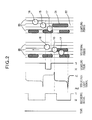
- Fig. 2 schematically shows a situation of the CD-R recording apparatus during recording and tracking.
- a recording signal is changed alternately to a low (L) level equivalent to a reading power level and a high (H) level equivalent to a recording power level, and the guide groove is irradiated with a laser beam modulated in accordance with the recording signal.
- the laser beam with which the guide groove is irradiated is reflected to reach an optical pickup again, and then converted into an electric signal by a photodetector to be outputted.
- An outputted signal of the reflected light becomes a fully reflected level until a pit is formed, thus exhibiting a sudden level increase.
- the signal is increased to Pw equivalent to the recording power level and, when pit formation is started, energy is absorbed to reduce the signal level. During the pit formation, a stable level is exhibited.
- a reflection signal output also becomes Pr equivalent to the reading power level.
- waveform correction of the recording signal called a write strategy is carried out to set desired pit and blank lengths.
- the recording signal and the reflection signal are consequently deviated from each other in certain parts, but a detail is omitted.
- a servo sampling pulse is issued, and servo sampling is carried out in a predetermined section of the reading power level Pr to generate a tracking error signal.
- a preceding sub beam 16 is placed on an unrecorded track, while a succeeding sub beam 17 partially overlaps the pit in which recording is currently carried out by the main beam 15. During this period, however, tracking error signal generation is not carried out.
- a tracking error signal obtained in a blank section immediately before is held to control tracking.
- the succeeding sub beam 17 is shift in a blank portion and, in this blank portion, servo sampling is carried out to generate a tracking error signal. That is, during the tracking error signal generation, since the preceding and succeeding sub beams 16 and 17 are both placed in the blank portion, no difference is generated in the amounts of reflected lights between both of the sub beams 16 and 17 while the main 15 beam follows around the guide groove 20.
- Figs. 3(A) and 3(B) are schematic views when recording is carried out while increasing the laser power to widely and intensively form pits. Fig.
- FIG. 3(A) shows a state during the servo sampling, i.e., a state immediately before a succeeding sub beam 17 reaches a blank position to issue a sampling pulse. If a sampling pulse is issued, and a tracking error signal is sampled, the following problem is observed to occur.
- the preceding sub beam 16 is in an unrecorded guide groove (i.e., blank portion), while the succeeding sub beam 17 partially overlaps the wide pit 21 in which high laser power recording has been carried out one round before to thereby reduce the amount of a reflected light of the sub beam 17.
- an error occurs because the tracking error signal is a differential signal between both of the sub beams 16 and 17 and, by its impulse response, an undesirable track jump occurs.
- 3(B) is a view schematically showing a relation between the observed tracking error signal and guide groove tracking.
- the tracking error signal is controlled nearly to a zero value to carry out stable tracking.
- the aforementioned tracking error signal is generated when the position of the pit widely formed at high laser power one round previously is reached and, by an impulse response to a noise signal, an undesirable track jump is caused.
- an undesirable track jump is caused.
- only slight oscillation occurs.
- this oscillation occurs during subsequent rounds and, by this undesirable tracking error signal, a tracking servo becomes unstable.
- the inventive optical recording apparatus comprises a rotating means that is provided for rotating an optical disk which is formed thereon with a guide groove to define a spiral track having a plurality of rounds, an optical pickup that has a light source for generating an optical beam and a diffractive grating for diffracting the optical beam to form a main beam and a pair of sub beams opposite with each other relative to the main beam, the optical pickup being operable for irradiating the main beam to the spiral track with accompanying the pair of the sub beams along apposite sides of the spiral track, a servo means that operates the optical pickup to enable the main beam to trace the spiral track based on a tracking error signal derived from return lights of the sub beams reflected back from the optical disk, a recording means that modulates the main beam for recording of information onto the spiral track while the optical dick is rotated, and a control means that controls recording of information each cycle the optical disk is rotated such that the recording of
- control means operates when the recording of information to a current round of the spiral track is finished for controlling the servo means to jump the main beam from an end of the current round to an end of a next round of the spiral track so as to blank the next round.
- control means operates when the recording of information to a current round of the spiral track is finished for controlling the recording means to disable the main beam for one cycle of the rotation until the main beam reaches an end of a next round of the spiral track so as to blank the next round.
- control means controls the servo means and the recording means for performing a session of recording information by alternating the filled rounds and the blanked rounds, and performing an additional session of recording information selectively into the blanked rounds of the spiral track while skipping the filled rounds of the spiral track.
- the recording means modulates an intensity of the optical beam according to information representative of an image for forming pits and lands along the spiral track to thereby draw the image on the optical disk.
- FIG. 1 is a constitutional view of the invention.
- An optical disk 1 is tightly held by a clamper and a turntable, and rotated by a spindle motor 2.
- the spindle motor 2 is equipped with a frequency generator (FG, hereinafter) 3.
- the FG 3 comprises a hall element arranged radially around a rotary shaft of the spindle motor 2, and generates a predetermined number of pulse signals during one rotation cycle of the rotary shaft.
- the pulse signals outputted from the FG 3 are used as rotational speed signals.
- FG/spindle motor control means (rotation control means, hereinafter) 4 receives each rotational speed signal, inspects a rotational speed, and returns a control signal to the spindle motor 2 so as to set a desired rotational speed.
- the optical disk 1 is disposed so that its recording surface can face an optical pickup 6.
- the optical pickup 6 incorporates a predetermined optical system and a predetermined driving system (not shown), and is attached to the outside.
- the optical pickup 6 irradiates a guide groove beforehand formed in the optical disk with three optical beams of a zero-order light and positive and negative first-order lights obtained by passing an optical beam emitted from an incorporated light source through a diffraction grating, and records information while carrying out tracking control by using a tracking error signal so that the zero-order light can trace the guide groove by using the positive and negative first-order lights among the three optical beams.
- a low-pass component signal of the tracking error signal is used to carry out feed control for transferring the optical pickup 6 in a radial direction of the optical disk 1, and a focus error signal is used to carry out focus control.
- a laser beam emitted from the optical pickup 6 to the optical disk 1 receives intensity modulation such as energy absorption when the laser beam is reflected on the recording surface, and reaches the optical pickup 6 again.
- the arrived reflected light is converted into an electric signal by a photodetector and outputted to tracking/focus/feed servo means (servo means, hereinafter) 7.
- the servo means 7 uses a predetermined photodetector output to generate a servo control signal, and returns the signal to the optical pickup 6 to carry out loop control.
- a differential signal is obtained between output signals of the photodetector receiving both of the reflected sub beam lights to generate a tracking error signal, and to form a tracking servo loop.
- a reflection signal is also outputted to automatic laser power control means (ALPC, hereinafter) 8.
- the ALPC 8 compares a reflection signal level with a predetermined level to carry out control so that laser power can become an optimal level.
- Recording information transferred from a host computer to form a visible image is received through an interface (I/F, hereinafter) 9 and temporarily saved in an image data memory 10.
- the recording information contains a code which indicates an image gradation.
- recording waveform correction formation is carried out by laser pulse gradation control means 12 so as to set desired gradation.
- the recording signal is turned into multiple pulses, and its duty is changed by a gradation code to make a thick or thin adjustment.
- a power level is changed by a gradation code to make a density adjustment.
- starting and trailing ends of the recording signal are changed by a gradation code to make a crude density adjustment. Needless to say, these may be combined to make a total adjustment.
- a corrected recording signal generated by the laser pulse gradation control means 12 is outputted to the ALPC to become a desired laser power pulse, and emitted to the optical disk 1 to form an image.
- the recording means may receive information, then generating a recording waveform according to the received information, and modulating an intensity of the main beam based on the recording waveform so as to record the information onto the spiral track.
- the recording means may receive a signal representative of the information, then adjusting a recording waveform according to the received signal, and modulating an intensity of the main beam based on the adjusted recording waveform so as to record the information.
- the present invention further comprises draw timing control means 11.
- the draw timing control means 11 comprises clock generation means. This clock signal is used to count pulses of a rotational speed signal outputted from the rotation control means 4. When a predetermined number of pulses is reached during one rotation of the rotary shaft of the spindle motor 2, a timing signal is outputted to the image data memory 10, the laser pulse gradation control means 12 and control means 5 for resetting.
- the image data memory 10 receives the timing signal, and outputs recording signal information of one round from a predetermined memory address.
- the laser pulse gradation control means 12 receives the timing signal, and reads the recording signal information of one round from the image data memory 10 to start recording signal waveform correction formation.
- the control means 5 sends a track jump signal to servo means 7, and a laser power setting signal to the ALPC 8.
- Fig. 4 shows an embodiment of the present invention.
- the control means 5 upon a start of recording from a predetermined position, the control means 5 resets the draw timing control means 11.
- a timing signal is generated from the draw timing control means 11, and the control means 5 which receives the timing signal sends one track jump signal to the servo means 7.
- the optical pickup 6 which receives the one track jump signal jumps the main beam to a track one round outside to continue recording. Thereafter, the same operation is carried out for each one rotation.
- the operation under control of the control means 5 never causes instability of the servo means 7.
- Fig. 5 shows another embodiment of the present invention.
- the number of track jumps is two or more.
- the control means 5 controls recording of information each cycle the optical disk is rotated such that the recording of information is enabled to fill one round of the spiral track 20 and disabled to blank another round of the spiral track 20 so as to alternate the filled rounds and the blanked rounds.
- the control means 5 operates when the recording of information to a current round of the spiral track 20 is finished for controlling the servo means 7 to jump the main beam from an end of the current round to an end of a next round of the spiral track 20 so as to blank the next round.
- Fig. 6 shows yet another embodiment of the present invention.
- recording is carried out again from an original position at an unrecorded round between the recorded rounds.
- the recording mode of Fig. 4 which is an origin, for a recording start position, an address position specified by the control means 5 is searched, and recording is started from a position which address is found.
- a start specified address is searched, and the draw timing control means 11 is reset in a found position.
- the main beam follows the guide groove at a reading power level for one round, then carries out one track jump upon reception of a timing signal, and sets laser power to a recording power level.
- control means controls the servo means 5 and the recording means 7 for performing an interleaving session of recording information by alternating the filled rounds and the blanked rounds, and performing an interposing session of recording information 21' selectively into the blanked rounds of the spiral track 20 while skipping the filled rounds of the spiral track 20.
- not one track jump but one round tracking where the laser power is set to a reading level can be used. Tracking tolerance in reading needs not be stricter than that in recording and, even when slight deviation occurs, it can be solved by returning. Additionally, an impulse response can be prevented by reducing a servo gain during a reading level round. That is, the control means 5 sends not a track jump signal but a servo gain control signal to the servo means in accordance with a timing signal, whereby the prevention can be achieved. Needless to say, simultaneously, the ALPC 8 sends a laser power control signal to make a laser power adjustment.
- control means 5 operates when the recording of information to a current round of the spiral track is finished for controlling the recording means to disable the main beam for one cycle of the rotation until the main beam reaches an end of a next round of the spiral track so as to blank the next round.
- Data memory means is disposed in place of the image data memory means 10 of Fig. 1, and an eight-to-fourteen modulation (EFM) encoder and write strategy means are disposed in place of the laser pulse gradation control means 12.
- EFM eight-to-fourteen modulation
- a recording signal transferred from a host computer is temporarily stored in the data memory means, and subjected to EFM encoding.
- EFM signal subjected to the EFM encoding is further subjected to waveform correction by the write strategy means, and laser emission recording is carried out by an ALPC 8, interleaving round recording and interposing round recording can be carried out similarly.
- the optical disk recording apparatus of the present invention which uses the CD-R recording medium to form an image on the recording surface based on areas, sizes or a crude density of pits has been described with reference to the case where the pits are formed deeply, densely or widely by the high laser power.
- a similar phenomenon occurs when recording is carried out on an optical disk manufactured by narrow track pitches. That is, the phenomenon occurs when recording is carried out on the optical disk which enables recording/playback by using the same optical system but which is manufactured by narrow track pitches to increase a recording capacity.
- the narrow track pitch optical disk it is possible to carry out interleaving round recording and interposing round recording similarly.
Landscapes
- Optical Recording Or Reproduction (AREA)
- Moving Of The Head For Recording And Reproducing By Optical Means (AREA)
- Optical Head (AREA)
Abstract
Description
Fig. 3(B) is a view schematically showing a relation between the observed tracking error signal and guide groove tracking. During the guide groove tracking, the tracking error signal is controlled nearly to a zero value to carry out stable tracking. However, the moment another round is made, the aforementioned tracking error signal is generated when the position of the pit widely formed at high laser power one round previously is reached and, by an impulse response to a noise signal, an undesirable track jump is caused. Depending on a magnitude of the response, only slight oscillation occurs. However, this oscillation occurs during subsequent rounds and, by this undesirable tracking error signal, a tracking servo becomes unstable.
Namely, the inventive optical recording apparatus comprises a rotating means that is provided for rotating an optical disk which is formed thereon with a guide groove to define a spiral track having a plurality of rounds, an optical pickup that has a light source for generating an optical beam and a diffractive grating for diffracting the optical beam to form a main beam and a pair of sub beams opposite with each other relative to the main beam, the optical pickup being operable for irradiating the main beam to the spiral track with accompanying the pair of the sub beams along apposite sides of the spiral track, a servo means that operates the optical pickup to enable the main beam to trace the spiral track based on a tracking error signal derived from return lights of the sub beams reflected back from the optical disk, a recording means that modulates the main beam for recording of information onto the spiral track while the optical dick is rotated, and a control means that controls recording of information each cycle the optical disk is rotated such that the recording of information is enabled to fill one round of the spiral track and disabled to blank another round of the spiral track so as to alternate the filled rounds and the blanked rounds.
Claims (8)
- An optical recording apparatus comprising:a rotating means for rotating an optical disk which is formed thereon with a guide groove to define a spiral track having a plurality of rounds;an optical pickup having a light source for generating an optical beam and a diffractive grating for diffracting the optical beam to form a main beam and a pair of sub beams opposite with each other relative to the main beam, the optical pickup being operable for irradiating the main beam to the spiral track with accompanying the pair of the sub beams along apposite sides of the spiral track;a servo means for operating the optical pickup to enable the main beam to trace the spiral track based on a tracking error signal derived from return lights of the sub beams reflected back from the optical disk;a recording means modulating the main beam for recording of information onto the spiral track while the optical dick is rotated; anda control means for controlling recording of information each cycle the optical disk is rotated such that the recording of information is enabled to fill one round of the spiral track and disabled to blank another round of the spiral track so as to alternate the filled rounds and the blanked rounds.
- The optical recording apparatus according to claim 1, wherein the control means operates when the recording of information to a current round of the spiral track is finished for controlling the servo means to jump the main beam from an end of the current round to an end of a next round of the spiral track so as to blank the next round.
- The optical recording apparatus according to claim 1, wherein the control means operates when the recording of information to a current round of the spiral track is finished for controlling the recording means to disable the main beam for one cycle of the rotation until the main beam reaches an end of a next round of the spiral track so as to blank the next round.
- The optical recording apparatus according to claim 1, wherein the control means controls the servo means and the recording means for performing a session of recording information by alternating the filled rounds and the blanked rounds, and performing an additional session of recording information selectively into the blanked rounds of the spiral track while skipping the filled rounds of the spiral track.
- The optical recording apparatus according to claim 1, wherein the recording means modulates an intensity of the optical beam according to information representative of an image for forming pits and lands along the spiral track to thereby draw the image on the optical disk.
- An optical recording apparatus for recording information on an optical disk, comprising:a rotating means for rotating the optical disk which is formed thereon with a guide groove to define a spiral track having a plurality of rounds;a detecting means for detecting a rotation signal representative of a rotation speed of the rotating means;a regulating means for regulating the rotating means in response to the rotation signal;an optical pickup having a light source for generating an optical beam and a diffractive grating for diffracting the optical beam to form a main beam and a pair of sub beams opposite with each other relative to the main beam, the optical pickup being operable for irradiating the main beam to the spiral track with accompanying the pair of the sub beams along apposite sides of the spiral track;a servo means for operating the optical pickup to enable the main beam to trace the spiral track based on a tracking error signal derived from return lights of the sub beams reflected back from the optical disk;a recording means for receiving information, then generating a recording waveform according to the received information, and modulating an intensity of the main beam based on the recording waveform so as to record the information onto the spiral track;a timing means receptive of the rotation signal for outputting a timing signal each cycle the optical disk is rotated such that the timing signal indicates recording of the information into each round of the spiral track; anda control means responsive to the timing signal for controlling either of the servo means or the recording means so as to alternate a filled round recorded with the information and a black round not recorded with the information by jumping the main beam by one round each time the timing signal is outputted or by suppressing the optical beam at least every one after another round.
- An optical recording apparatus for recording information on an optical disk, comprising:a rotating means for rotating the optical disk which is formed thereon with a guide groove to define a spiral track having a plurality of rounds;a detecting means for detecting a rotation signal representative of a rotation speed of the rotating means;a regulating means for regulating the rotating means in response to the rotation signal;an optical pickup having a light source for generating an optical beam and a diffractive grating for diffracting the optical beam to form a main beam and a pair of sub beams opposite with each other relative to the main beam, the optical pickup being operable for irradiating the main beam to the spiral track with accompanying the pair of the sub beams along apposite sides of the spiral track;a servo means for operating the optical pickup to enable the main beam to trace the spiral track based on a tracking error signal derived from return lights of the sub beams reflected back from the optical disk;a recording means for receiving a signal representative of the information, then adjusting a recording waveform according to the received signal, and modulating an intensity of the main beam based on the adjusted recording waveform so as to record the information;a timing means receptive of the rotation signal for outputting a timing signal each cycle the optical disk is rotated such that the timing signal indicates recording of the information into each round of the spiral track; anda control means responsive to the timing signal for controlling either of the servo means or the recording means so as to alternate a filled round recorded with the information and a black round not recorded with the information by jumping the main beam by one round each time the timing signal is outputted or by suppressing the optical beam at least every one after another round.
- A method of recording information on an optical disk by means of an optical pickup having a light source generating an optical beam and a diffractive grating for diffracting the optical beam to form a main beam and a pair of sub beams opposite with each other relative to the main beam, the method comprising the steps of:rotating the optical disk which is formed thereon with a guide groove to define a spiral track having a plurality of rounds;operating the optical pickup for irradiating the main beam to the spiral track with accompanying the pair of the sub beams along apposite sides of the spiral track;further operating the optical pickup to enable the main beam to trace the spiral track based on a tracking error signal derived from return lights of the sub beams reflected back from the optical disk;modulating the main beam for recording of the information onto the spiral track while the optical dick is rotated; andcontrolling the recording of the information each cycle the optical disk is rotated such that the recording of the information is enabled to fill one round of the spiral track and disabled to blank another round of the spiral track so as to alternate the filled rounds and the blanked rounds.
Applications Claiming Priority (2)
| Application Number | Priority Date | Filing Date | Title |
|---|---|---|---|
| JP2002182141 | 2002-06-21 | ||
| JP2002182141A JP3972741B2 (en) | 2002-06-21 | 2002-06-21 | Optical disk recording device |
Publications (2)
| Publication Number | Publication Date |
|---|---|
| EP1376554A2 true EP1376554A2 (en) | 2004-01-02 |
| EP1376554A3 EP1376554A3 (en) | 2006-11-15 |
Family
ID=29717549
Family Applications (1)
| Application Number | Title | Priority Date | Filing Date |
|---|---|---|---|
| EP03014071A Withdrawn EP1376554A3 (en) | 2002-06-21 | 2003-06-23 | Optical recording apparatus with interleaving blank rounds into spiral track |
Country Status (4)
| Country | Link |
|---|---|
| US (1) | US6980495B2 (en) |
| EP (1) | EP1376554A3 (en) |
| JP (1) | JP3972741B2 (en) |
| CN (1) | CN1251192C (en) |
Families Citing this family (6)
| Publication number | Priority date | Publication date | Assignee | Title |
|---|---|---|---|---|
| US20030090970A1 (en) * | 2001-11-12 | 2003-05-15 | Matsushita Electric Industrial Co., Ltd. | Optical head and optical disk device |
| JP2006236514A (en) * | 2005-02-28 | 2006-09-07 | Hitachi Media Electoronics Co Ltd | Diffraction grating, optical pickup and optical disc apparatus |
| JP4321469B2 (en) * | 2005-03-24 | 2009-08-26 | ソニー株式会社 | Disc recording apparatus and method, and recording control program |
| US20070236556A1 (en) * | 2006-04-08 | 2007-10-11 | Kuohua Wu | Impinging optical beam on regions of label surface at different power levels |
| JP2009140583A (en) * | 2007-12-07 | 2009-06-25 | Yamaha Corp | Optical disk drawing device |
| US8369198B2 (en) * | 2008-02-05 | 2013-02-05 | Mediatek Inc. | System and method for printing visible image onto optical disc through tuning driving signal of optical pick-up unit |
Family Cites Families (12)
| Publication number | Priority date | Publication date | Assignee | Title |
|---|---|---|---|---|
| JPH01130327A (en) * | 1987-11-16 | 1989-05-23 | Olympus Optical Co Ltd | Optical information recording and reproducing device |
| JPH083910B2 (en) * | 1989-01-13 | 1996-01-17 | シャープ株式会社 | Optical pickup device |
| US5161134A (en) * | 1989-06-29 | 1992-11-03 | Digital Equipment Corporation | Method for increasing linear bit density in magneto-optical storage media |
| JP2760882B2 (en) * | 1990-05-09 | 1998-06-04 | 株式会社日立製作所 | Multi-beam optical disk device and recording / reproducing method |
| US5500840A (en) * | 1991-12-13 | 1996-03-19 | Canon Kabushiki Kaisha | Method and apparatus for accessing reading and/or writing means to a desired region on an information recording medium on which a plurality of tracks are spirally formed, in accordance with an estimated arrival position |
| US5774439A (en) * | 1993-09-16 | 1998-06-30 | Matsushira Electric Industrial Co., Ltd. | Optical-disk recording and reproducing apparatus and optical disk for recording information on lands and grooves |
| JPH07110956A (en) * | 1993-10-13 | 1995-04-25 | Hitachi Ltd | Recording / reproducing apparatus for disc-shaped recording medium |
| JPH11144362A (en) * | 1997-11-07 | 1999-05-28 | Teac Corp | Information recording / reproducing device |
| KR100282939B1 (en) * | 1997-11-25 | 2001-03-02 | 윤종용 | Spindle Motor Rotation Speed Control Method in Optical Disc Drive |
| JP4265002B2 (en) * | 1998-10-02 | 2009-05-20 | ソニー株式会社 | Optical information recording apparatus and optical information recording method |
| JP2001056937A (en) * | 1999-08-17 | 2001-02-27 | Nec Corp | Marking device for optical disk |
| JP4278820B2 (en) * | 2000-03-31 | 2009-06-17 | パイオニア株式会社 | optical disk |
-
2002
- 2002-06-21 JP JP2002182141A patent/JP3972741B2/en not_active Expired - Fee Related
-
2003
- 2003-06-20 US US10/600,691 patent/US6980495B2/en not_active Expired - Fee Related
- 2003-06-23 EP EP03014071A patent/EP1376554A3/en not_active Withdrawn
- 2003-06-23 CN CN03149177.4A patent/CN1251192C/en not_active Expired - Fee Related
Also Published As
| Publication number | Publication date |
|---|---|
| CN1471089A (en) | 2004-01-28 |
| US20040008593A1 (en) | 2004-01-15 |
| EP1376554A3 (en) | 2006-11-15 |
| JP2004030728A (en) | 2004-01-29 |
| US6980495B2 (en) | 2005-12-27 |
| CN1251192C (en) | 2006-04-12 |
| JP3972741B2 (en) | 2007-09-05 |
Similar Documents
| Publication | Publication Date | Title |
|---|---|---|
| EP1308938B1 (en) | Apparatus for recording data and visible images on an optical disc | |
| US6781937B2 (en) | Optical disk recording method and device | |
| EP0317193B1 (en) | Optical disc recording system | |
| EP1191523B1 (en) | An optical recording apparatus, and a method for controlling laser power therein | |
| US6996047B2 (en) | Optical disc recording method and apparatus | |
| US7633847B2 (en) | Recording apparatus and recording method | |
| US6980495B2 (en) | Optical recording apparatus with interleaving blank rounds into spiral track | |
| EP0814464B1 (en) | Method of manufacturing an optical disk | |
| US6980497B2 (en) | Optical disk recording apparatus and control method thereof | |
| US20020006089A1 (en) | Optical recording and reproducing apparatus, tilt correction method, tilt correction program and medium | |
| US4797870A (en) | Optical recording and reproducing apparatus | |
| JP2004355764A (en) | Optical disk apparatus and program | |
| JP2006040508A (en) | Optical information recording device | |
| JPH09312021A (en) | Recording medium recording device, recording medium recording method, and recording medium | |
| KR100438565B1 (en) | Method for controlling recording light source of an optical recording apparatus, especially regarding to preventing pit width from narrowing in a split part | |
| JP2000113454A (en) | Optical disk recorder | |
| EP1490869A1 (en) | Optical disc drive and method for controlling the same | |
| JP3723529B2 (en) | Optical head light emission output control device for optical disk recording device | |
| JP2008204518A (en) | Optical disc reproducing method and optical disc reproducing apparatus | |
| JP2003281729A (en) | Optical disk drive | |
| JP2006338810A (en) | Spherical aberration correction method for optical disk recording/reproducing device | |
| JP2003173532A (en) | Light emission output control method for optical head | |
| JP2006236431A (en) | Aberration correcting method for optical disk recording and reproducing device | |
| JP2005149640A (en) | Optical disc and optical disc apparatus | |
| JP2003132539A (en) | Optical disc recording device |
Legal Events
| Date | Code | Title | Description |
|---|---|---|---|
| PUAI | Public reference made under article 153(3) epc to a published international application that has entered the european phase |
Free format text: ORIGINAL CODE: 0009012 |
|
| AK | Designated contracting states |
Kind code of ref document: A2 Designated state(s): AT BE BG CH CY CZ DE DK EE ES FI FR GB GR HU IE IT LI LU MC NL PT RO SE SI SK TR |
|
| AX | Request for extension of the european patent |
Extension state: AL LT LV MK |
|
| PUAL | Search report despatched |
Free format text: ORIGINAL CODE: 0009013 |
|
| AK | Designated contracting states |
Kind code of ref document: A3 Designated state(s): AT BE BG CH CY CZ DE DK EE ES FI FR GB GR HU IE IT LI LU MC NL PT RO SE SI SK TR |
|
| AX | Request for extension of the european patent |
Extension state: AL LT LV MK |
|
| 17P | Request for examination filed |
Effective date: 20061214 |
|
| 17Q | First examination report despatched |
Effective date: 20070119 |
|
| RAP1 | Party data changed (applicant data changed or rights of an application transferred) |
Owner name: YAMAHA CORPORATION |
|
| AKX | Designation fees paid |
Designated state(s): DE FR GB |
|
| GRAP | Despatch of communication of intention to grant a patent |
Free format text: ORIGINAL CODE: EPIDOSNIGR1 |
|
| STAA | Information on the status of an ep patent application or granted ep patent |
Free format text: STATUS: THE APPLICATION IS DEEMED TO BE WITHDRAWN |
|
| 18D | Application deemed to be withdrawn |
Effective date: 20081209 |