EP1376541A2 - Extraction of external noise components - Google Patents
Extraction of external noise components Download PDFInfo
- Publication number
- EP1376541A2 EP1376541A2 EP03253100A EP03253100A EP1376541A2 EP 1376541 A2 EP1376541 A2 EP 1376541A2 EP 03253100 A EP03253100 A EP 03253100A EP 03253100 A EP03253100 A EP 03253100A EP 1376541 A2 EP1376541 A2 EP 1376541A2
- Authority
- EP
- European Patent Office
- Prior art keywords
- acoustic signal
- band
- band level
- processing apparatus
- level
- Prior art date
- Legal status (The legal status is an assumption and is not a legal conclusion. Google has not performed a legal analysis and makes no representation as to the accuracy of the status listed.)
- Ceased
Links
Images




Classifications
-
- G—PHYSICS
- G10—MUSICAL INSTRUMENTS; ACOUSTICS
- G10L—SPEECH ANALYSIS TECHNIQUES OR SPEECH SYNTHESIS; SPEECH RECOGNITION; SPEECH OR VOICE PROCESSING TECHNIQUES; SPEECH OR AUDIO CODING OR DECODING
- G10L21/00—Speech or voice signal processing techniques to produce another audible or non-audible signal, e.g. visual or tactile, in order to modify its quality or its intelligibility
- G10L21/02—Speech enhancement, e.g. noise reduction or echo cancellation
-
- G—PHYSICS
- G10—MUSICAL INSTRUMENTS; ACOUSTICS
- G10L—SPEECH ANALYSIS TECHNIQUES OR SPEECH SYNTHESIS; SPEECH RECOGNITION; SPEECH OR VOICE PROCESSING TECHNIQUES; SPEECH OR AUDIO CODING OR DECODING
- G10L21/00—Speech or voice signal processing techniques to produce another audible or non-audible signal, e.g. visual or tactile, in order to modify its quality or its intelligibility
- G10L21/02—Speech enhancement, e.g. noise reduction or echo cancellation
- G10L21/0208—Noise filtering
- G10L2021/02082—Noise filtering the noise being echo, reverberation of the speech
Definitions
- the present invention relates to an acoustic signal processing apparatus and method, and an audio device. More particularly, the present invention relates to the art of extracting external noise components contained in acoustic signals.
- Fig. 8 shows an acoustic signal processing apparatus of the related art for extracting external noise contained in an acoustic signal.
- a speaker 10 outputs an acoustic signal corresponding to audio input to a sound playback system.
- the sound playback system has external noise.
- a microphone 11 converts the noisy acoustic signal into an electrical signal, and outputs it to a subtractor 12.
- An FIR (Finite Impulse Response) digital filter 13 outputs a simulated impulse response of the sound playback system to the subtractor 12.
- the output of the FIR filter 13 corresponds to a noiseless audio signal taking the sound playback system into account, and the external noise component is output from the subtractor 12.
- the apparatus of the related art has drawbacks.
- the impulse response of the sound playback system in the car audio system has a length of about 4,000 sampling points given that the sampling frequency is 44.1 kHz.
- the FIR filter 13 must have about 4,000 taps, which makes the apparatus costly.
- the FIR filter 13 must perform a large volume of computations, resulting in high power consumption due to heat, etc.
- the number of sum-of-product computations required per sampling time (1/44100 Hz ⁇ 0.023 msec) for FIR filtering by the FIR filter 13 with, for example, 4,096 taps is given by 4096 ⁇ 2
- the number of sum-of-product computations required per second is given by (4096 ⁇ 2)
- ⁇ 44100 361,267,200.
- an object of the present invention to provide an acoustic signal processing apparatus and method, and an audio device in which external noise can be accurately estimated with less computation.
- an acoustic signal processing apparatus includes a first band analyzer for dividing an acoustic signal input from a sound playback system via an input unit into a plurality of frequency bands and for outputting a first band level for each band; an acoustic signal estimator for estimating the band level of the original acoustic signal at the input unit and for outputting a second band level for each band; and a processor for extracting an external noise component which is contained in the acoustic signal using the first band level and the second band level.
- the acoustic signal is divided into a plurality of frequency bands and the band level is output for each band, thus allowing a frequency characteristic of the acoustic signal to be represented by the band level for each band, so that the amount of computation required can be greatly reduced.
- the apparatus can therefore be compact and low-cost.
- the number of bands divided is set as desired, thus achieving a compact and low-cost apparatus with high accuracy.
- the acoustic signal estimator may include a second band analyzer for dividing an audio signal corresponding to the acoustic signal, which has not been supplied to the sound playback system, into the plurality of frequency bands and for outputting a third band level; and a calculator for correcting the third band level according to an acoustic characteristic of the sound playback system which is in the state where the sound playback system does not have the external noise component.
- the calculator is the model of a noiseless sound playback system.
- the external noise component is obtained by subtracting the second band level output from the acoustic signal estimator from the first band level.
- the calculator may multiply the third band level by a coefficient for correction.
- the acoustic signal estimator may include a coefficient adjusting unit for adjusting the value of the coefficient. With adjustment of the coefficient, the apparatus can support a variety of sound playback systems.
- the acoustic signal estimator may selectively output a plurality of second band levels depending upon a state of the sound playback system. Therefore, a second band level suitable for the sound playback system can be easily selected, for each band, from the plurality of second band levels using a simple mechanism.
- the processor may subtract the second band level from the first band level.
- the first band analyzer, the acoustic signal estimator, and the processor may be formed on a single chip.
- the band level may be a mean level for each frequency band.
- an audio signal processing method includes a step of dividing an acoustic signal input from a sound playback system via an input unit into a plurality of frequency bands and outputting a first band level; a step of estimating the band level of the original acoustic signal at the input unit and outputting a second band level for each band; and a step of extracting a noise component which is contained in the acoustic signal using the first band level and the second band level. Therefore, a system for carrying out the method can be compact and low-cost. The number of bands is set as desired, thus achieving a compact and low-cost system with high accuracy.
- an audio device in another aspect of the present invention, includes an audio source for generating an audio signal, and a correction unit for correcting the audio signal.
- the correction unit includes the above-noted acoustic signal processing apparatus, and a corrector for correcting the audio signal according to the external noise component output from the acoustic signal processing apparatus. Since an acoustic signal for canceling masking caused by external noise present in the environment where the audio device is installed can be output, a problem that music is suppressed by the external noise and cannot be thus heard is overcome.
- the correction unit may include a filter for performing audio correction on the audio signal according to the external noise component.
- the correction unit may include an audio corrector.
- Fig. 1 shows an acoustic signal processing apparatus and method according to a first embodiment of the present invention.
- An acoustic signal processing circuit 20 includes a band analyzer 21, an acoustic signal estimator 22, and a band level subtractor 23.
- the acoustic signal processing circuit 20 further includes input terminals 26 and 28, and output terminals 27.
- a microphone 11 is connected to the input terminal 26 of the acoustic signal processing circuit 20.
- An audio signal is supplied to the speaker 10 and is also supplied to the input terminal 28.
- An electrical signal (external noise signal) corresponding to external noise extracted in the way described below is input to the output terminal 27 for each band.
- the band analyzer 21 which functions as a first band analyzer divides the acoustic signal input from a sound playback system via the input terminal 26 serving as an input unit into frequency bands, and outputs a first band level.
- the acoustic signal estimator 22 estimates the band level of the original acoustic signal at the input terminal 26, and outputs a second band level for each band.
- the acoustic signal of the input terminal 26 means an output signal of a microphone 11 connected to the input terminal 26.
- the band level subtractor 23 which functions as a processor subtracts the second band level from the first band level to extract an external noise component contained in the acoustic signal.
- the acoustic signal estimator 22 includes a band analyzer 24 and a multiplier group 25.
- the band analyzer 24 which functions as a second band analyzer divides the acoustic signal which has not been input to the sound playback system, i.e., the audio signal applied to the speaker 10 and the input terminal 28, into frequency bands, and outputs a third band level.
- the multiplier group 25 which functions as a calculator corrects the third band level according to an acoustic characteristic of the sound playback system assuming that the sound playback system is noiseless. In this way, the acoustic signal estimator 22 shown in Fig. 1 uses the audio signal applied to the speaker 10 to estimate the band level of the original (noiseless) acoustic signal (audio signal) at the microphone 11.
- the band analysis performed by the band analyzers 21 and 24 includes dividing the frequency band of the audio signal to define a plurality of bands (frequency widths), and outputting the band level for each band.
- the frequency characteristic of the acoustic signal is represented by the band level for each band.
- An example of the band level is the mean level for each band.
- the signal level at a certain frequency can be calculated by, for example, performing FFT (Fast Fourier Transform) on an input signal. The signal levels at some frequencies are determined for each band to calculate the average thereof, thereby obtaining the band level.
- Each multiplier of the multiplier group 25 corresponds to each band, and multiplies the band level of the corresponding band by a predetermined coefficient.
- the value of the coefficient set for each band depends upon the sound playback system.
- the multiplier group 25 multiplies the band level output from the band analyzer 24 by the coefficient which depends upon a frequency characteristic of the pure (or noiseless) sound playback system to estimate the band level of the original acoustic signal (audio signal) at the microphone 11.
- the multiplier group 25 is therefore a circuit that models the sound playback system.
- the band level subtractor 23 subtracts the second band level output from the acoustic signal estimator 22 from the first band level output from the band analyzer 21, and outputs the subtraction result to the output terminal 27.
- the resulting output signal of the acoustic signal processing apparatus 20 is an external noise signal indicating the band level of external noise estimated for each band.
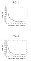
- Fig. 2 is a graph showing the measured band level of the noise signal
- Fig. 3 is a graph showing the estimated band level input to the output terminal 27 of the acoustic signal processing apparatus 20
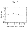
- Fig. 4 is a graph showing the difference (error) between the measured band level and the estimated band level.
- the x-axis designates the band number.
- the audio signal is equally divided into 16 frequency bands. For example, given that the audio signal has a frequency bandwidth of 20 kHz, each band has a frequency bandwidth of 1250 Hz.
- the y-axis designates the gain (dB).
- the y-axis designates the error (dB).
- the band level of the noise signal can be estimated with an error range of about 2 dB. Furthermore, the acoustic signal processing apparatus 20 requires much less computation than the apparatus of the related art.
- the number of computations required in the present invention is about 1/221 of the number of computations required in the related art, i.e., 361,267,200, and can be greatly reduced. Therefore, external noise can be accurately estimated with fewer computations, thus making the acoustic signal processing apparatus 20 compact and low-cost with low power consumption.
- the number of bands divided is not limited to 16, and the signal may be divided into any number of frequency bands.
- the more frequency bands the signal is divided into the more precise adjustment of frequency division can be achieved while more computation is required.
- the fewer frequency bands the signal is divided into the less precisely adjusted can be frequency division although less computation is required.
- the number of bands should be set as desired in view of this point.
- Fig. 5A shows the circuit structure of the multiplier group 25 for each band.
- the multiplier group 25 includes a multiplier 31i and a coefficient generator 32i.
- the multiplier 31i multiplies the i-th band level Si output from the band analyzer 24 by a coefficient ⁇ i generated by the coefficient generator 32i.
- the calculation result, i.e., Si ⁇ i is the estimated value of the i-th band level of the acoustic signal at the microphone 11.
- the coefficients ⁇ 1 through an for the bands are set to values according to the sound playback system, where n indicates an integer more than one. That is, the coefficients ⁇ 1 through an for the bands are set to desired values to obtain models of the sound playback system. If the coefficients ⁇ 1 through an are fixed, only one model of the sound playback system can be obtained.
- a mechanism capable of varying the coefficient ⁇ i is preferable for supporting a variety of sound playback systems.
- the mechanism has two types of structures.
- the coefficient ⁇ i may vary consecutively.
- the coefficient ⁇ i may vary discretely.
- the first type of mechanism in which the coefficient ⁇ i is consecutively variable supports any type of sound playback system.
- some coefficient values ⁇ i are stored in advance, from which an appropriate value is selected. For example, a plurality of typical models of sound playback systems are prepared, and sets of coefficients in correspondence therewith are stored in a register or the like.
- the coefficient ⁇ i is controlled by, for example, a controller of the acoustic signal processing apparatus 20.
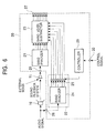
- Fig. 6 shows the configuration of the acoustic signal processing apparatus 20 including a controller 29.
- the controller 29 controls the coefficient generator 32i.
- the controller 29 adjusts the coefficient value ⁇ i for each band in response to the control signal so that the output of the band level subtractor 23, which is obtained when an appropriate audio signal is supplied to the speaker 10, has an error within a predetermined range (for example, 2 dB, as described above with reference to Fig. 4).
- sets of discrete coefficient values are prepared, and the set of values which provides the minimum output error of the band level subtractor 23 is selected.
- the desired set of discrete coefficient values may be selected without calculation of the error.
- a signal corresponding to the set of values specified by a user is supplied to the control terminal 30, and the controller 29 selects, in response, the specified set of coefficient values.
- coefficients are prepared in advance for car types, and the user operates an audio device (described below) so that the desired signal corresponding to the switching operation can be selected.
- the band analyzers 21 and 24 perform FFT; however, any other device can be used to determine the band level for each band.
- bandpass filters having different passbands can be used to constitute the band analyzers 21 and 24.
- the widths of the bands are equal; however, the bandwidths may be different. For example, relatively broad bandwidths may be provided in the mid-low frequency range, and relatively narrow bandwidths may be provided in the high frequency range. With the bandwidths weighted in this way, the sound playback system can be more strictly modeled. However, weighting the bandwidth increases the complexity in circuit configuration and computation processing. In view of such situations, the equal bandwidth or weighted bandwidth may be chosen as required.
- the acoustic signal processing apparatus 20 may further include, for example, a DSP (digital signal processor).
- the DSP is a one-chip semiconductor device having a circuit suitable for quickly repeating sum-of-product computation. As described above, since the number of required computations can be greatly reduced according to this embodiment, a compact DSP may be used, thus reducing the circuit size and the cost while achieving high speed operation and low power consumption.
- Fig. 7 is a diagram of an audio device according to a second embodiment of the present invention.
- the same parts as those described above with reference to Figs. 1 through 6 are designated by the same reference numerals.
- the audio device shown in Fig. 7 includes an audio source 34, a correction unit 35, and the above-described acoustic signal processing apparatus 20.
- the audio source 34 reads audio information such as music from a recording medium such as a CD-ROM (compact disc read-only memory), an MD (Mini Disc), or a cassette tape for playback, and outputs an audio signal to the correction unit 35.
- the correction unit 35 includes an audio correction coefficient generator 36, and an audio correction filter 37.
- the audio correction filter 37 multiplies the audio signal by an audio correction coefficient generated by the audio correction coefficient generator 36 to perform audio correction.
- the audio correction coefficient generator 36 adjusts the value of the audio correction coefficient according to the output signal of the acoustic signal processing apparatus 20, i.e., the external noise signal output from the output terminal 27. That is, the correction unit 35 performs filtration so that the acoustic signal led to the sound playback system via the speaker 10 contains a component for canceling the external noise.
- the correction unit 35, the speaker 10, the sound playback system, the microphone 11, and the acoustic signal processing apparatus 20 form a single loop, thus allowing time-varying external noise to be detected in real time to perform real-time audio correction on the audio signal output from the audio source 34.
- the speaker 10 and/or the microphone 11 may be accommodated by the audio device, or may be external to the audio device.
Landscapes
- Engineering & Computer Science (AREA)
- Computational Linguistics (AREA)
- Quality & Reliability (AREA)
- Signal Processing (AREA)
- Health & Medical Sciences (AREA)
- Audiology, Speech & Language Pathology (AREA)
- Human Computer Interaction (AREA)
- Physics & Mathematics (AREA)
- Acoustics & Sound (AREA)
- Multimedia (AREA)
- Circuit For Audible Band Transducer (AREA)
- Measurement Of Mechanical Vibrations Or Ultrasonic Waves (AREA)
- Control Of Amplification And Gain Control (AREA)
Abstract
Description
Claims (10)
- An acoustic signal processing apparatus (20) comprising:a first band analyzer (21) for dividing an acoustic signal input from a sound playback system via an input unit (26) into a plurality of frequency bands and for outputting a first band level;an acoustic signal estimator (22) for estimating the band level of the original acoustic signal at the input unit (26) and for outputting a second band level for each band; anda processor (23) for extracting an external noise component which is contained in the acoustic signal using the first band level and the second band level.
- An acoustic signal processing apparatus (20) according to claim 1, wherein the acoustic signal estimator (22) includes:a second band analyzer (24) for dividing an audio signal corresponding to the acoustic signal, which has not been supplied to the sound playback system, into the plurality of frequency bands and for outputting a third band level; anda calculator (25) for correcting the third band level according to an acoustic characteristic of the sound playback system which is in the state where the sound playback system does not have the external noise component.
- An acoustic signal processing apparatus (20) according to claim 1, wherein the acoustic signal estimator (22) includes:a second band analyzer (24) for dividing an audio signal corresponding to the acoustic signal, which has not been supplied to the sound playback system, into the plurality of frequency bands and for outputting a third band level; anda calculator (25) for multiplying the third band level by a coefficient according to an acoustic characteristic of the sound playback system.
- An acoustic signal processing apparatus (20) according to claim 3, wherein the acoustic signal estimator (22) further includes a coefficient adjusting unit (32i) for adjusting the value of the coefficient.
- An acoustic signal processing apparatus (20) according to claim 1, wherein the acoustic signal estimator (22) selectively outputs a plurality of second band levels depending upon a state of the sound playback system.
- An acoustic signal processing apparatus (20) according to any one of claims 1 through 5, wherein processor (23) subtracts the second band level from the first band level.
- An acoustic signal processing apparatus (20) according to any one of claims 1 through 6, wherein the first band analyzer (21), the acoustic signal estimator (22), and the processor (23) are formed on a single chip.
- An acoustic signal processing apparatus (20) according to any one of claims 1 through 7, wherein the band level comprises a mean level for each frequency band.
- An audio device, including an acoustic signal processing apparatus as claimed in any preceding claim.
- An audio signal processing method comprising:a step of dividing an acoustic signal input from a sound playback system via an input unit into a plurality of frequency bands and outputting a first band level;a step of estimating the band level of the original acoustic signal at the input unit and outputting a second band level for each band; anda step of extracting a noise component which is contained in the acoustic signal using the first band level and the second band level.
Applications Claiming Priority (2)
| Application Number | Priority Date | Filing Date | Title |
|---|---|---|---|
| JP2002176326 | 2002-06-17 | ||
| JP2002176326A JP2004023481A (en) | 2002-06-17 | 2002-06-17 | Acoustic signal processing apparatus and method therefor, and audio system |
Publications (2)
| Publication Number | Publication Date |
|---|---|
| EP1376541A2 true EP1376541A2 (en) | 2004-01-02 |
| EP1376541A3 EP1376541A3 (en) | 2006-08-23 |
Family
ID=29717453
Family Applications (1)
| Application Number | Title | Priority Date | Filing Date |
|---|---|---|---|
| EP03253100A Ceased EP1376541A3 (en) | 2002-06-17 | 2003-05-17 | Extraction of external noise components |
Country Status (3)
| Country | Link |
|---|---|
| US (1) | US7254242B2 (en) |
| EP (1) | EP1376541A3 (en) |
| JP (1) | JP2004023481A (en) |
Cited By (1)
| Publication number | Priority date | Publication date | Assignee | Title |
|---|---|---|---|---|
| EP2556608A4 (en) * | 2010-04-09 | 2017-01-25 | DTS, Inc. | Adaptive environmental noise compensation for audio playback |
Families Citing this family (33)
| Publication number | Priority date | Publication date | Assignee | Title |
|---|---|---|---|---|
| JP4235128B2 (en) * | 2004-03-08 | 2009-03-11 | アルパイン株式会社 | Input sound processor |
| EP1619793B1 (en) | 2004-07-20 | 2015-06-17 | Harman Becker Automotive Systems GmbH | Audio enhancement system and method |
| JP4381291B2 (en) * | 2004-12-08 | 2009-12-09 | アルパイン株式会社 | Car audio system |
| US8170221B2 (en) * | 2005-03-21 | 2012-05-01 | Harman Becker Automotive Systems Gmbh | Audio enhancement system and method |
| US7596231B2 (en) * | 2005-05-23 | 2009-09-29 | Hewlett-Packard Development Company, L.P. | Reducing noise in an audio signal |
| US8345890B2 (en) | 2006-01-05 | 2013-01-01 | Audience, Inc. | System and method for utilizing inter-microphone level differences for speech enhancement |
| US8194880B2 (en) | 2006-01-30 | 2012-06-05 | Audience, Inc. | System and method for utilizing omni-directional microphones for speech enhancement |
| US8744844B2 (en) | 2007-07-06 | 2014-06-03 | Audience, Inc. | System and method for adaptive intelligent noise suppression |
| US9185487B2 (en) | 2006-01-30 | 2015-11-10 | Audience, Inc. | System and method for providing noise suppression utilizing null processing noise subtraction |
| US8204252B1 (en) | 2006-10-10 | 2012-06-19 | Audience, Inc. | System and method for providing close microphone adaptive array processing |
| US7991494B2 (en) | 2006-02-23 | 2011-08-02 | Lg Electronics Inc. | Method and apparatus for processing an audio signal |
| US8150065B2 (en) * | 2006-05-25 | 2012-04-03 | Audience, Inc. | System and method for processing an audio signal |
| US8849231B1 (en) | 2007-08-08 | 2014-09-30 | Audience, Inc. | System and method for adaptive power control |
| US8949120B1 (en) | 2006-05-25 | 2015-02-03 | Audience, Inc. | Adaptive noise cancelation |
| US8204253B1 (en) | 2008-06-30 | 2012-06-19 | Audience, Inc. | Self calibration of audio device |
| US8934641B2 (en) | 2006-05-25 | 2015-01-13 | Audience, Inc. | Systems and methods for reconstructing decomposed audio signals |
| US8259926B1 (en) | 2007-02-23 | 2012-09-04 | Audience, Inc. | System and method for 2-channel and 3-channel acoustic echo cancellation |
| US8189766B1 (en) | 2007-07-26 | 2012-05-29 | Audience, Inc. | System and method for blind subband acoustic echo cancellation postfiltering |
| US8180064B1 (en) | 2007-12-21 | 2012-05-15 | Audience, Inc. | System and method for providing voice equalization |
| US8143620B1 (en) | 2007-12-21 | 2012-03-27 | Audience, Inc. | System and method for adaptive classification of audio sources |
| US8194882B2 (en) | 2008-02-29 | 2012-06-05 | Audience, Inc. | System and method for providing single microphone noise suppression fallback |
| US8355511B2 (en) | 2008-03-18 | 2013-01-15 | Audience, Inc. | System and method for envelope-based acoustic echo cancellation |
| US8774423B1 (en) | 2008-06-30 | 2014-07-08 | Audience, Inc. | System and method for controlling adaptivity of signal modification using a phantom coefficient |
| US8521530B1 (en) | 2008-06-30 | 2013-08-27 | Audience, Inc. | System and method for enhancing a monaural audio signal |
| JP2011064961A (en) * | 2009-09-17 | 2011-03-31 | Toshiba Corp | Audio playback device and method |
| US9838784B2 (en) | 2009-12-02 | 2017-12-05 | Knowles Electronics, Llc | Directional audio capture |
| US9008329B1 (en) | 2010-01-26 | 2015-04-14 | Audience, Inc. | Noise reduction using multi-feature cluster tracker |
| US9640194B1 (en) | 2012-10-04 | 2017-05-02 | Knowles Electronics, Llc | Noise suppression for speech processing based on machine-learning mask estimation |
| US9536540B2 (en) | 2013-07-19 | 2017-01-03 | Knowles Electronics, Llc | Speech signal separation and synthesis based on auditory scene analysis and speech modeling |
| US9799330B2 (en) | 2014-08-28 | 2017-10-24 | Knowles Electronics, Llc | Multi-sourced noise suppression |
| WO2016040885A1 (en) | 2014-09-12 | 2016-03-17 | Audience, Inc. | Systems and methods for restoration of speech components |
| US9820042B1 (en) | 2016-05-02 | 2017-11-14 | Knowles Electronics, Llc | Stereo separation and directional suppression with omni-directional microphones |
| US12205609B1 (en) * | 2023-07-21 | 2025-01-21 | Krisp Technologies, Inc. | Generating parallel data for real-time speech form conversion |
Family Cites Families (10)
| Publication number | Priority date | Publication date | Assignee | Title |
|---|---|---|---|---|
| JPH01296169A (en) * | 1988-05-24 | 1989-11-29 | Sony Corp | Spectrum analyzer |
| US5285165A (en) * | 1988-05-26 | 1994-02-08 | Renfors Markku K | Noise elimination method |
| JPH04123621A (en) * | 1990-09-14 | 1992-04-23 | Nippon Telegr & Teleph Corp <Ntt> | Echo eraser |
| US5625684A (en) * | 1993-02-04 | 1997-04-29 | Local Silence, Inc. | Active noise suppression system for telephone handsets and method |
| JPH07202998A (en) | 1993-12-29 | 1995-08-04 | Nec Corp | Telephone set provided with peripheral noise eliminating function |
| JP3403549B2 (en) * | 1995-05-29 | 2003-05-06 | 松下電器産業株式会社 | Echo canceller |
| DE69634027T2 (en) * | 1995-08-14 | 2005-12-22 | Nippon Telegraph And Telephone Corp. | Acoustic subband echo canceller |
| JP3099870B2 (en) * | 1996-07-23 | 2000-10-16 | 日本電気株式会社 | Acoustic echo canceller |
| US5970154A (en) * | 1997-06-16 | 1999-10-19 | Industrial Technology Research Institute | Apparatus and method for echo cancellation |
| US6377637B1 (en) * | 2000-07-12 | 2002-04-23 | Andrea Electronics Corporation | Sub-band exponential smoothing noise canceling system |
-
2002
- 2002-06-17 JP JP2002176326A patent/JP2004023481A/en active Pending
-
2003
- 2003-05-17 EP EP03253100A patent/EP1376541A3/en not_active Ceased
- 2003-06-03 US US10/453,918 patent/US7254242B2/en not_active Expired - Fee Related
Cited By (1)
| Publication number | Priority date | Publication date | Assignee | Title |
|---|---|---|---|---|
| EP2556608A4 (en) * | 2010-04-09 | 2017-01-25 | DTS, Inc. | Adaptive environmental noise compensation for audio playback |
Also Published As
| Publication number | Publication date |
|---|---|
| US20040037439A1 (en) | 2004-02-26 |
| US7254242B2 (en) | 2007-08-07 |
| EP1376541A3 (en) | 2006-08-23 |
| JP2004023481A (en) | 2004-01-22 |
Similar Documents
| Publication | Publication Date | Title |
|---|---|---|
| US7254242B2 (en) | Acoustic signal processing apparatus and method, and audio device | |
| US7155385B2 (en) | Automatic gain control for adjusting gain during non-speech portions | |
| CN101048935B (en) | Method and apparatus for controlling unit loudness or partial unit loudness of an audio signal | |
| US6529605B1 (en) | Method and apparatus for dynamic sound optimization | |
| KR100312636B1 (en) | Compensation Filter | |
| EP2226794B1 (en) | Background noise estimation | |
| CA2358203A1 (en) | Method and apparatus for adaptively suppressing noise | |
| US20080063229A1 (en) | Band-limited adaptive feedback canceller for hearing aids | |
| EP0727769A2 (en) | Method of and apparatus for noise reduction | |
| JP2010532879A (en) | Adaptive intelligent noise suppression system and method | |
| EP1129448B1 (en) | System for measuring signal to noise ratio in a speech signal | |
| JP4274949B2 (en) | Audio feedback processing system | |
| JPH06310962A (en) | Automatic sound volume control device | |
| AU1679097A (en) | A noisy speech parameter enhancement method and apparatus | |
| JP2010019902A (en) | Volume adjusting device, volume adjusting method and volume adjusting program | |
| EP2234105A1 (en) | Background noise estimation | |
| JP5216125B2 (en) | Dynamic acoustic optimization method and apparatus | |
| WO2006011104A1 (en) | Audio signal dereverberation | |
| JP2000115883A (en) | Audio system | |
| WO2004086362A1 (en) | Speech signal compression device, speech signal compression method, and program | |
| US20040125962A1 (en) | Method and apparatus for dynamic sound optimization | |
| CN118474607A (en) | Active noise reduction method and device and active noise reduction earphone | |
| US7254245B2 (en) | Circuit and method for adaptation of hearing device microphones | |
| JP3322479B2 (en) | Audio equipment | |
| US6959277B2 (en) | Voice feature extraction device |
Legal Events
| Date | Code | Title | Description |
|---|---|---|---|
| PUAI | Public reference made under article 153(3) epc to a published international application that has entered the european phase |
Free format text: ORIGINAL CODE: 0009012 |
|
| AK | Designated contracting states |
Kind code of ref document: A2 Designated state(s): AT BE BG CH CY CZ DE DK EE ES FI FR GB GR HU IE IT LI LU MC NL PT RO SE SI SK TR |
|
| AX | Request for extension of the european patent |
Extension state: AL LT LV MK |
|
| PUAL | Search report despatched |
Free format text: ORIGINAL CODE: 0009013 |
|
| AK | Designated contracting states |
Kind code of ref document: A3 Designated state(s): AT BE BG CH CY CZ DE DK EE ES FI FR GB GR HU IE IT LI LU MC NL PT RO SE SI SK TR |
|
| AX | Request for extension of the european patent |
Extension state: AL LT LV MK |
|
| 17P | Request for examination filed |
Effective date: 20070108 |
|
| 17Q | First examination report despatched |
Effective date: 20070305 |
|
| AKX | Designation fees paid |
Designated state(s): DE FR GB |
|
| APBN | Date of receipt of notice of appeal recorded |
Free format text: ORIGINAL CODE: EPIDOSNNOA2E |
|
| APBR | Date of receipt of statement of grounds of appeal recorded |
Free format text: ORIGINAL CODE: EPIDOSNNOA3E |
|
| APAF | Appeal reference modified |
Free format text: ORIGINAL CODE: EPIDOSCREFNE |
|
| APBT | Appeal procedure closed |
Free format text: ORIGINAL CODE: EPIDOSNNOA9E |
|
| STAA | Information on the status of an ep patent application or granted ep patent |
Free format text: STATUS: THE APPLICATION HAS BEEN REFUSED |
|
| 18R | Application refused |
Effective date: 20130228 |