EP1376217A1 - Lenticular lens sheet having light-shielding layer and method for manufacture thereof - Google Patents
Lenticular lens sheet having light-shielding layer and method for manufacture thereof Download PDFInfo
- Publication number
- EP1376217A1 EP1376217A1 EP02701607A EP02701607A EP1376217A1 EP 1376217 A1 EP1376217 A1 EP 1376217A1 EP 02701607 A EP02701607 A EP 02701607A EP 02701607 A EP02701607 A EP 02701607A EP 1376217 A1 EP1376217 A1 EP 1376217A1
- Authority
- EP
- European Patent Office
- Prior art keywords
- light
- lens sheet
- lenticular lens
- layer
- silver salt
- Prior art date
- Legal status (The legal status is an assumption and is not a legal conclusion. Google has not performed a legal analysis and makes no representation as to the accuracy of the status listed.)
- Withdrawn
Links
Images


Classifications
-
- G—PHYSICS
- G03—PHOTOGRAPHY; CINEMATOGRAPHY; ANALOGOUS TECHNIQUES USING WAVES OTHER THAN OPTICAL WAVES; ELECTROGRAPHY; HOLOGRAPHY
- G03B—APPARATUS OR ARRANGEMENTS FOR TAKING PHOTOGRAPHS OR FOR PROJECTING OR VIEWING THEM; APPARATUS OR ARRANGEMENTS EMPLOYING ANALOGOUS TECHNIQUES USING WAVES OTHER THAN OPTICAL WAVES; ACCESSORIES THEREFOR
- G03B21/00—Projectors or projection-type viewers; Accessories therefor
- G03B21/54—Accessories
- G03B21/56—Projection screens
- G03B21/60—Projection screens characterised by the nature of the surface
- G03B21/62—Translucent screens
- G03B21/625—Lenticular translucent screens
-
- G—PHYSICS
- G03—PHOTOGRAPHY; CINEMATOGRAPHY; ANALOGOUS TECHNIQUES USING WAVES OTHER THAN OPTICAL WAVES; ELECTROGRAPHY; HOLOGRAPHY
- G03B—APPARATUS OR ARRANGEMENTS FOR TAKING PHOTOGRAPHS OR FOR PROJECTING OR VIEWING THEM; APPARATUS OR ARRANGEMENTS EMPLOYING ANALOGOUS TECHNIQUES USING WAVES OTHER THAN OPTICAL WAVES; ACCESSORIES THEREFOR
- G03B21/00—Projectors or projection-type viewers; Accessories therefor
- G03B21/54—Accessories
- G03B21/56—Projection screens
- G03B21/60—Projection screens characterised by the nature of the surface
- G03B21/602—Lenticular screens
Definitions
- the present invention relates to a lenticular lens sheet for use in a rear projection screen. More particularly, it relates to a lenticular lens sheet including on its light-emerging surface side a light-shielding layer, and to a process of producing the same.
- a so-called projection-type television which an image is projected from the rear and the projected image is viewed from the front, is known as a large-screen television.
- a projection-type television includes an imaging light source and a rear projection screen for displaying thereon an image projected from the imaging light source.
- CRT's cathode-ray tubes
- LCD liquid crystal display
- DLP digital light processing
- DMD's digital micro-mirror devices
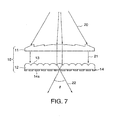
- Fig. 7 is a view showing an example of a rear projection screen for use in a projection-type television.
- a rear projection screen 10 is composed of a Fresnel lens sheet (Fresnel convex lens) 11 and a lenticular lens sheet 12, where an image projected from an imaging light source (not shown in the figure) located at the rear of the rear projection screen 10 (upside in the figure) is viewed by a viewer who is in front of the rear projection screen 10 (downside in the figure) .
- an imaging light source not shown in the figure
- the lenticular lens sheet 12 for use in such a rear projection screen 10 contains, on its light-emerging surface side, a light-shielding layer 14 in order to prevent reflection of extraneous light (light that enters from the downside in Fig. 7) to improve image contrast.
- the light-shielding layer 14 has light-shielding areas (black stripes) 14a that correspond to the non-light-converging parts of the lenticular lenses 13.
- the light-shielding areas 14a in the light-shielding layer 14 can be created by coating, with a material capable of shielding light, those parts with a certain width of the light-emerging surface of the lenticular lens sheet 12 that correspond to the non-light-converging parts of the lenticular lenses 13.
- an LCD or DLP projector, or the like has come to be used, instead of a CRT, in a projection-type television as an imaging light source.
- An image projected from such a light source is composed of dot matrixes and has sharper definition.
- a so-called fine-pitch lenticular lens sheet 12 with a lens pitch smaller than that required for the magnifying projection of an image on a CRT has come to be demanded.
- the lenticular lenses are required to have a fine pitch between 0.05 mm and 0.3 mm.
- the method described in Japanese Laid-Open Patent Publication No. 120102/1997 has been known as a method of creating light-shielding areas 14a in a light-shielding layer 14 that is used in a fine-pitch lenticular lens sheet 12 of the above-described type.
- an ionizing-radiation-curing resin layer is formed on the flat surface of a lenticular lens sheet opposite to the lens-provided surface (the surface on which lenticular lenses are formed), and ultraviolet light is applied to the lenticular lens sheet from the lens-provided surface side to expose the ionizing-radiation-curing resin layer, thereby curing those parts of the resin layer that are in the positions corresponding to the light-converging parts of the lenticular lenses.
- a toner or transfer ink layer (black in color) is adhered to the surfaces of those parts of the resin layer that are in the positions corresponding to the non-light-converging parts of the lenticular lenses.
- a light-shielding layer having therein a predetermined light-shielding pattern is thus formed on the lenticular lens sheet on its light-emerging surface side.
- the lenticular lens sheet produced by the method described in the above publication is at a disadvantage in that the light-shielding pattern in the light-shielding layer is poor in positional accuracy.
- Another drawback is as follows: the light-shielding effect of the light-shielding layer is insufficient, so that when this lenticular lens sheet is combinedwitha light-converging lens means such as a Fresnel lens sheet to make a rear projection screen, sufficiently high optical efficiency cannot be obtained, and, in addition, it is highly possible that high image contrast cannot be obtained.
- the process of creating the light-shielding areas requires the step of forming an ionizing-radiation-curing resin layer; the step of curing, by exposure, those parts of the resin layer that are in the positions corresponding to the light-converging parts of the lenticular lenses, leaving the surfaces of the other parts of the resin layer sticky; the step of adhering a toner or transfer ink layer to the non-light-converging parts; and so forth.
- This method thus requires a large number of steps, so that it is poor in efficiency.
- An object of the present invention is therefore to provide a lenticular lens sheet that comprises a light-shielding layer having a light-shielding pattern formed with high positional accuracy and that ensures sufficiently high image contrast even when it is combined with a light-converging lens means such as a Fresnel lens sheet to make a rear projection screen, and a process of producing such a lenticular lens sheet.
- Another object of the present invention is to provide a lenticular lens sheet for use in a rear projection screen, that comprises a light-shielding layer and that can be produced with higher efficiency, and a process of producing such a lenticular lens sheet.
- the light-shielding layer that is formed on the lenticular lens sheet on its light-emerging surface side is made from a silver salt emulsion (a silver salt photosensitive material) which is widely used in the fields of photography and medical service.
- a silver salt emulsion layer is laminated to the light-emerging surface of the lenticular lens sheet opposite to its lens-provided surface (the surface on which lenticular lenses are formed).
- Exposure light is applied to the lenticular lens sheet from its lens-provided surface side to expose the silver salt emulsion layer, and development is then conducted to darken the unexposed parts of the silver salt emulsion layer, whereby a light-shielding layer with a predetermined light-shielding pattern is formed on the lenticular lens sheet on its light-emerging surface side. It is thus possible to obtain the light-shielding pattern of the light-shielding layer with high positional accuracy. Further, it is possible to vary the degree of darkening of the uncured parts according to the rate of exposure of the silver salt emulsion layer or to the degree of development.
- the optical transmission density of the light-shielding areas in the light-shielding layer is made especially high, there can be obtained a lenticular lens sheet for use in a rear projection screen, having low reflectance for extraneous light, that is, capable of attaining high image contrast.
- a lenticular lens sheet comprising: a light-transmitting lens sheet body having a lenticular lens group consisting of multiple lenticular lenses arranged on one surface; and a light-shielding layer made from a silver salt emulsion, laminated to the other surface of the lenticular lens sheet body; wherein the light-shielding layer has light-transmitting areas in the positions corresponding to the light-converging parts of the lenticular lenses on the lens sheet body, and light-shielding areas that are in the positions corresponding to the non-light-converging parts of the lenticular lenses and that have light-shielding characteristics owing to the darkened silver dispersed in the silver salt emulsion.
- the light-shielding areas in the light-shielding layer have an optical transmission density of preferably 2 or more, more preferably 3 or more.
- the lens sheet body is preferably a transparent, single-layer sheet with the lenticular lens group integrally shaped.
- the lens sheet body includes a transparent film, and a lenticular lens layer with the lenticular lens group shaped, the lenticular lens layer being laminated to the transparent film.
- the light-shielding layer be laminated to the surface of the lens sheet body opposite to the surface having the lenticular lens group, with a transparent film different from the lens sheet body being disposed between the lens sheet body and the light-shielding layer.
- the transparent film, to which the light-shielding layer is laminated may be laminated to the surface of the lens sheet body opposite to the surface having the lenticular lens group with the use of an adhesive agent layer.
- the lenticular lens sheet further comprises a plate-like supporting member capable of transmitting light, the supporting member being laminated to the lens sheet body on the lenticular lens group side or the light-shielding layer side.
- the outermost surface of the lenticular lens sheet on the light-shielding layer side has a reflectance of not more than 10%. Further, it is preferable that the light-shielding areas in the light-shielding layer have, for light of 700 nm, a spectral reflectance 90 to 110% of that for light of 400 nm.
- the present invention provides, as a second aspect, a process of producing a lenticular lens sheet, comprising the steps of: preparing a light-transmitting lens sheet body having a lenticular lens group consisting of multiple lenticular lenses arranged on one surface; laminating a silver salt emulsion layer to the other surface of the lenticular lens sheet body; applying exposure light to the lens sheet body from the lenticular lens group side to expose those parts of the silver salt emulsion layer that correspond to the light-converging parts of the lenticular lenses; and developing the silver salt emulsion layer to obtain a light-shielding layer having light-transmitting areas in the positions corresponding to the light-converging parts of the lenticular lenses, and light-shielding areas that are in the positions corresponding to the non-light-converging parts of the lenticular lenses and that have light-shielding characteristics owing to the darkened silver dispersed in the silver salt emulsion.
- the silver salt emulsion layer is developed so that the light-shielding areas in the light-shielding layer can have an optical transmission density of preferably 2 or more, more preferably 3 or more.
- the lens sheet body it is preferable to prepare, for the lens sheet body, a transparent, single-layer sheetwith the lenticular lens group integrally shaped.
- the process further preferably comprises the steps of: preparing a mold roll for shaping lenticular lenses, whose periphery, serving as a mold face, is provided with grooves in the inverse shape of the lenticular lens group; winding a transparent film around the mold face of the mold roll, with an ionizing-radiation-curing resin composition between the mold face of the mold roll and the transparent film; and applying ionizing radiation to the mold roll through the transparent film to cure the ionizing-radiation-curing resin composition; whereby a sheet including a transparent film, and a lenticular lens layer with the lenticular lens group shaped, the lenticular lens layer being laminated to the transparent film, is prepared for the lens sheet body.
- the lamination of the silver salt emulsion layer to the surface of the lens sheet body opposite to the surface having the lenticular lens group be conducted by applying a silver salt emulsion to the former surface of the lens sheet body and drying the silver salt emulsion applied.
- the lamination of the silver salt emulsion layer to the surface of the lens sheet body opposite to the surface having the lenticular lens group be conducted by backing a silver salt emulsion layer with a transparent film to obtain a silver salt photosensitive film and adhering this silver salt photosensitive film to the lens sheet body, with the transparent film of the photosensitive film facing the surface of the lens sheet body opposite to the surface having the lenticular lens group.
- the parallel rays it is preferable to use parallel rays for the exposure light. It is herein preferable that the parallel rays have a parallelism of 0°. It is also preferable that the parallel rays have a parallelism of more than 0° and 10° or less.
- a Fresnel printer, or a system composed of a light source and a louver through which light from the source can pass can be used as an exposure system capable of applying the parallel rays.
- the light-shielding layer laminated to the surface of the lens sheet body opposite to the surface having the lenticular lens group is formed from a silver salt emulsion, and the light-transmitting areas and the light-shielding areas are created by patterning the light-shielding layer, making use of the difference in the degree of darkening of silver dispersed in the silver salt emulsion. It is therefore possible to make the light-shielding pattern in the light-shielding layer with high positionalaccuracy.
- the light-shielding areas in the light-shielding layer can shield light thanks to the darkened silver dispersed in the silver salt emulsion, so that the reflection of extraneous light on the front (viewing plane) side can effectively be suppressed. It is thus possible to obtain sufficiently high image contrast even when the lenticular lens sheet is combined with a light-converging lens means such as a Fresnel lens sheet to make a rear projection screen.
- the optical transmission density of the light-shielding areas in the light-shielding layer is made 2 or more, the light-shielding areas can surely show the light-shielding effect.
- the light-shielding areas in the light-shielding layer have low reflectance, the reflectance for extraneous light on the front (viewing plane) side can be suppressed to low.
- the optical transmission density of the light-shielding areas in the light-shielding layer is made 3 or more, the light-shielding areas can more surely show the light-shielding effect.
- the light-shielding areas in the light-shielding layer have low reflectance, the reflectance for extraneous light on the front (viewing plane) side can be suppressed to lower.
- the lens sheet body if a transparent, single-layer sheet with a lenticular lens group integrally shaped is prepared for the lens sheet body, it becomes possible to simplify the structure of the lens sheet body.
- the lens sheet body if a transparent film, to which a lenticular lens layer having the lenticular lens group shaped is laminated, is prepared for the lens sheet body, it becomes possible to make the lens sheet body with high accuracy and efficiency.
- the light-shielding layer made from a silver salt emulsion may be laminated to the lens sheet body with a transparent film different from the lens sheet body being disposed between the lens sheet body and the light-shielding layer, a silver salt photosensitive film such as a conventional photographic silver salt film can be used to form the light-shielding layer.
- the transparent film, to which the light-shielding layer is laminated may be laminated to the lens sheet body with the use of an adhesive agent layer
- a silver salt photosensitive film such as a conventional photographic silver salt film can be used to form the light-shielding layer and can thus be readily fixed to the lens sheet body.
- the lenticular lens sheet further comprises a light-transmitting, plate-like supporting member laminated to the lens sheet body on its lenticular lens group side or the light-shielding layer side, it becomes self-supporting and can well maintain its shape even when it is in the standing state.
- the outermost surface of the lenticular lens sheet on its light-shielding layer side is made to have a reflectance of not more than 10%, the lowering of image contrast that is caused by extraneous light can be suppressed to extremely small.
- the light-shielding areas in the light-shielding layer are made to have, for light of 700 nm, a spectral reflectance 90 to 110% of that for light of 400 nm, they are seen black or nearly black and thus have lowered visual sensitivity. It is therefore possible to effectively prevent the lowering of image contrast that is caused by extraneous light.
- the light-shielding layer having a predetermined light-shielding pattern is formed on the lens sheet body on its light-emerging surface side in the following manner: a silver salt emulsion layer is laminated to the surface of the lens sheet body opposite to the surface having the lenticular lens group; exposure light is applied to the lens sheet body from the lenticular lens group side to expose the silver salt emulsion layer; and the silver salt emulsion layer is then developed to darken its unexposed parts. It is therefore possible to produce a lenticular lens sheet comprising the light-shielding layer with higher efficiency. It is also possible to form the light-shielding pattern in the light-shielding layer with high positional accuracy.
- the light-shielding areas in the light-shielding layer can shield light thanks to the darkened silver dispersed in the silver salt emulsion, so that it is possible to effectively suppress the reflection of extraneous light on the front (viewing plane) side. Sufficiently high image contrast can thus be obtained even when the lenticular lens sheet is combined with a light-converging lens means such as a Fresnel lens sheet to make a rear projection screen.
- the silver salt emulsion layer is developed so that the light-shielding areas in the light-shielding layer can have an optical transmission density of 2 or more, the light-shielding areas can surely show the light-shielding effect.
- the light-shielding areas in the light-shielding layer have low reflectance, the reflectance for extraneous light on the front (viewing plane) side can be suppressed to low.
- the silver salt emulsion layer is developed so that the light-shielding areas in the light-shielding layer can have an optical transmission density of 3 or more, the light-shielding areas can more surely show the light-shielding effect.
- the light-shielding areas in the light-shielding layer have low reflectance, the reflectance for extraneous light on the front (viewing plane) side can be suppressed to lower.
- the lens sheet body if a transparent, single-layer sheet with the lenticular lens group integrally shaped is prepared for the lens sheet body, it becomes possible to simplify the structure of the lens sheet body.
- a transparent film, to which a lenticular lens layer made from an ionizing-radiation-curing composition is laminated is prepared for the lens sheet body by the use of a mold roll for shaping lenticular lenses, whose periphery, serving as a mold face, is provided with grooves in the inverse shape of the lenticular lens group, it becomes possible to make the lens sheet body with high accuracy and efficiency.
- the lamination of the silver salt emulsion layer to the lens sheet body is conducted by applying a silver salt emulsion to the lens sheet body, and drying the silver salt emulsion layer applied, it becomes possible to make the lamination structure of the finally obtained lenticular lens sheet simple.
- the lamination of the silver salt emulsion layer to the lens sheet body is conducted by adhering a silver salt photosensitive film prepared by backing a silver salt emulsion layer with a transparent film, it is possible to form the silver salt emulsion layer with higher accuracy.
- the light-shielding areas can be accurately created in the light-shielding layer centered on the non-light-converging parts of the lenticular lenses.
- the parallelism of the parallel rays is made 0°, it is possible to accurately create, in the light-shielding layer, the light-shielding areas with a preferable width.
- the parallelism of the parallel rays is made more than 0° and 10° or less, it is possible to create, in the light-shielding layer, the light-shielding areas with the desired width.
- the second aspect of the present invention if a Fresnel printer is used as an exposure system capable of applying the parallel rays, it is possible to maintain the flatness of the lenticular lens sheet during exposure and thus to attain improved exposure accuracy.
- a system composed of a light source and a louver through which light from the light source can pass is used as an exposure system capable of applying the parallel rays, it is possible to conduct exposure while easily controlling the parallelism of the parallel rays.
- Fig. 1 is a cross-sectional view showing a lenticular lens sheet 1 according to an embodiment of the present invention.
- the lenticular lens sheet 1 contains a light-transmitting lens sheet body 2 having a lenticular lens group 3 consisting of multiple lenticular lenses 3a arranged on its upper surface.
- a light-shielding layer 4 made from a silver salt emulsion in which a silver salt is dispersed in an emulsion (silver salt photosensitive material).
- the light-shielding layer 4 has light-transmitting areas 4a in the positions corresponding to the light-converging parts of the lenticular lenses 3a on the lens sheet body 2, and light-shielding areas 4b that are in the positions corresponding to the non-light-converging parts of the lenticular lenses 3a (the areas between the light-transmitting areas 4a) and that have light-shielding characteristics owing to the darkened silver dispersed in the silver salt emulsion.
- the light-shielding areas 4b in the light-shielding layer 4 have an optical transmission density of preferably 2 or more, more preferably 3 or more. Both the light-transmitting areas 4a and the light-shielding areas 4b in the light-shielding layer 4 are created by exposing and developing the silver salt emulsion layer, as will be described later.
- the lens sheet body 2 in the lenticular lens sheet 1 shown in Fig. 1 is a transparent, single-layer sheet with the lenticular lens group 3 integrally shaped.
- the lenticular lens sheet of the present invention is not limited to this, and the lens sheet body 2 may be made by laminating, to a transparent film 6, a lenticular lens layer 7 having a lenticular lens group 3 consisting of multiple lenticular lenses 3a arranged, as shown in Fig. 2A.
- a light-shielding layer 4 having light-transmitting areas 4a and light-shielding areas 4b is laminated as in the lenticular lens sheet 1 shown in Fig. 1.
- the light-shielding layer 4 is directly laminated to the lower surface of the lens sheet body 2.
- the lenticular lens sheet of the present invention is not limited to this, and the light-shielding layer 4 may also be laminated to the lens sheet body 2, with a transparent film 8 different from the transparent film 6 of the lens sheet body 2 being disposed therebetween, as shown in Fig. 2B.
- a silver salt emulsion layer which it is not easy to uniformly form by coating, can be formed beforehand, by coating, on the transparent film 8 having no irregularities, so that it is possible to form a silver salt emulsion layer with higher accuracy.
- the transparent films 6 and 8 are herein fixed to each other with the use of an adhesive agent layer 9, as shown in Fig. 2B, or with a mechanical means.
- the structure of the lenticular lens sheet 1 shown in Fig. 2B can readily be attained by the use of a silver salt photosensitive film, such as a conventional photographic silver salt film, produced by laminating a silver salt emulsion layer to a transparent film.
- a silver salt photosensitive film such as a conventional photographic silver salt film, produced by laminating a silver salt emulsion layer to a transparent film.
- the structure of the lenticular lens sheet 1 shown in Fig. 2B (in which the light-shielding layer 4 is laminated to the lens sheet body 2, with the transparent film 8 (and the adhesive agent layer 9, if necessary) being disposed therebetween) is also applicable to the lenticular lens sheet 1 shown in Fig. 1.
- the lenticular lens sheet 1 shown in Fig. 1, 2A or 2B is in the form of an extremely thin film, so that it is not self-supporting and cannot well maintain its shape when it is in the standing state.
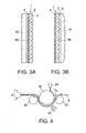
- a relatively-thick, self-supporting, light-transmitting sheet or plate (plate-like supporting member) 15 to the lens sheet body 2 on its light-shielding layer 4 side, preferably with the use of a transparent adhesive agent layer 9a, as shown in Fig. 3A.
- a transparent adhesive agent layer 9a for the sheet or plate 15, a light-diffusing one can be used.
- a sheet or plate 15 having, on one surface, a light-diffusing layer laminated may be used.
- a Fresnel lens sheet (Fresnel convex lens) 16 which is a light-converging lens means often used in combination with a lenticular lens sheet 1, may also be used as the plate-like supporting member.
- the Fresnel lens sheet 16 is laminated to the lens sheet body 2 on its lenticular lens group 3 side, preferably with the use of a transparent adhesive agent layer 9a, as shown in Fig. 3B.
- a Fresnel lens sheet (Fresnel convex lens), a light-converging lens means, is laminated to the lens sheet body 2 on its lenticular lens group 3 side, as shown in Fig. 3B, while a light-transmitting sheet or plate is laminated to the lens sheet body 2 on its light-shielding layer 4 side opposite to the lenticular lens group 3 side, as shown in Fig. 3A.
- a light-diffusing one, or a sheet or plate having, on one surface, a light-diffusing layer laminated can be used as in the lenticular lens sheet shown in Fig. 3A.
- the surface on the light-shielding layer 4 side is the viewing plane and is to face to a viewer. It is preferable that this viewing plane has extremely low reflectance for extraneous light. Specifically, it is preferable that the outermost surface of the lenticular lens sheet 1 on its light-shielding layer 4 side has a reflectance of not more than 10%. In the case where a light-transmitting sheet or plate 15 is laminated to the lenticular lens sheet 1 on its light-emerging surface side, as shown in Fig. 3A, it is preferable that the exposed surface of the sheet or plate 15 has a reflectance of not more than 10%.
- the light-shielding areas 4b in the light-shielding layer 4 be seen black or nearly black.
- the light-shielding areas 4b darkened areas, may be seen reddish or bluish. In the visible light range, however, it is preferable that the light-shielding areas 4b have flat or nearly flat reflection characteristics (reflectance for light versus wavelength of the light).
- the light-shielding areas 4b have a spectral reflectance, for light of 700 nm, 90 to 110% of that for light of 400 nm.
- the width of the light-shielding areas 4b in the light-shielding layer 4 is in the order of 0.3p to 0.9p when the pitch 2 of the lenticular lenses 3a in the lenticular lens group 3 formed on the opposite side of the light-shielding layer 4 is in the order of 50 to 300 ⁇ m.
- the pitch of the lenticular lenses 3a and the width of the light-shielding areas 4b may be properly determined, considering the use of the lenticular lens sheet, shaping accuracy, and so forth.
- a process of making the lens sheet body 2 of the lenticular lens sheet 1 is described with reference to Fig. 4.
- the lens sheet body 2 is composed of a transparent film 6 and a lenticular lens layer 7, as shown in Fig. 2A or 2B.
- a lens sheet body 2 as shown in Fig. 1 which is a transparent, single-layer sheet with a lenticular lens group integrally shaped, can be made by a shaping method using a mold or mold roll.
- a lens sheet body 2 as shown in Fig. 2A or 2B can be made more accurately and efficiently than a lens sheet body 2 as shown in Fig. 1.
- a transparent film 6 made of a transparent plastic film or the like which serves as a base film is unwound from the right-hand side in the figure, and is fed between a shaping roll 32 and a press roll 31 that are juxtaposed with each other.
- the shaping roll 32 rotates clockwise, while the press roll 31 rotates anti-clockwise.
- an ultraviolet-curing resin composition (ionizing-radiation-curing resin composition) 7a is fed from a dispenser 33 that is located diagonally above the shaping roll 32.
- the ultraviolet-curing resin composition 7a, now held between the shaping roll 32 and the transparent film 6, is carried under the shaping roll 32.
- the shaping roll 32 is a mold roll for shaping lenticular lenses, and has, on its periphery that serves as a mold face, a large number of grooves formed in parallel, in the inverse shape of the lenticular lens group consisting of multiple lenticular lenses arranged.
- the shaping roll 32 is usually metallic.
- An ultraviolet irradiation system 34 is located under the shaping roll 32 so that ultraviolet light can be applied upwardly to the shaping roll 32.
- the ultraviolet-curing resin composition 7a held between the shaping roll 32 and the transparent film 6 cures, and the cured ultraviolet-curing resin composition 7a is in the inverse shape of the grooves that are provided on the mold face of the shaping roll 32.
- a lenticular lens layer 7 having thereon a lenticular lens group is thus formed, and there is finally obtained a lens sheet body 2 composed of the transparent film 6 and the lenticular lens layer 7 laminated to the transparent film 6.
- This lens sheet body 2 being wound around the shaping roll 32 is carried to a peeling roll 35 located on the left-hand side of the shaping roll 32 in such a position that it can nip, together with the shaping roll 32, the lens sheet body 2, and is peeled from the shaping roll 32.
- a silver salt emulsion layer is laminated to the light-emerging surface (opposite to the surface having the lenticular lens group 3) of the lens sheet body 2 prepared in the above-described manner, and is successively subjected to exposure and development.
- a light-shielding layer 4 having light-transmitting areas 4a and light-shielding areas 4b is thus formed on the lens sheet body 2 on its light-emerging surface side.
- Fig. 5 is a view for illustrating the process of making a light-shielding layer 4 that is formed on the lens sheet body 2 on its light-emerging surface side.
- Production of a lenticular lens sheet 1 whose structure is as shown in Fig. 2B is herein taken as an example to describe the process. Basically the same process can be employed to produce a lenticular lens sheet 1 whose structure is as shown in Fig. 1 or 2A.
- a silver salt emulsion layer 10 is firstly laminated to the above-prepared lens sheet body 2 on its light-emerging surface side. Lamination of the silver salt emulsion layer 10 to the lens sheet body 2 is herein conducted in the following manner: a silver salt photosensitive film 5 is prepared by backing a silver salt emulsion layer 10 with a transparent film 8, and is adhered to the lens sheet body 2 with the use of an adhesive agent layer 9, with the transparent film 8 of the silver salt photosensitive film 5 facing the lens sheet body 2.
- lamination of the silver salt emulsion layer 10 to the lens sheet body 2 may also be conducted in the following manner: a silver salt emulsion is applied to the light-emerging surface of the lens sheet body 2 and is then dried to form a silver salt emulsion layer 10 directly on the light-emerging surface of the lens sheet body 2.
- a silver salt emulsion is applied to the light-emerging surface of the lens sheet body 2 and is then dried to form a silver salt emulsion layer 10 directly on the light-emerging surface of the lens sheet body 2.
- Obtainable in the latter manner is a lenticular lens sheet 1 whose structure is as shown in Fig. 1 or 2A.
- parallel rays (exposure light) 40 are applied to the lens sheet body 2 from the lenticular lens group 3 side (the lenticular lens layer 7 side) in the direction vertical to the lens sheet body 2.
- those parts of the silver salt emulsion layer 10 that correspond to the light-converging parts of the lenticular lenses 3a are exposed because the focal point of each lenticular lens 3a generally exists in the vicinity of the light-emerging surface of the lens sheet body 2.
- the silver salt emulsion layer 10 exposed in the above- described manner is developed. Specifically, when the silver salt emulsion layer 10 is of negative type, reversal development is conducted, while when it is of positive type, development suited to the formulation of the layer is conducted.
- a light-shielding layer 4 having light-transmitting areas 4a in the positions corresponding to the light-converging parts of the lenticular lenses 3a and light-shielding areas 4b that are in the positions corresponding to the non-light-converging parts of the lenticular lenses 3a and that have light-shielding characteristics owing to the darkened silver dispersed in the silver salt emulsion.
- the silver salt emulsion layer 10 is fully developed to such an extent that the darkened light-shielding areas 4b in the light-shielding layer 4 can have an optical transmission density of preferably 2 or more, more preferably 3 or more.
- a contact aligner which can make diffused light from a light source into parallel rays.
- a Fresnel printer which can make diffused light from a light source into parallel rays.
- the use of a Fresnel printer makes it possible to conduct exposure while keeping the lenticular lens sheet in contact with the exposure system (contact bake) ; the flatness of the lenticular lens sheet can thus be well maintained during exposure.
- a Fresnel lens capable of covering the slit width may be used as a means for making diffused light from a light source into parallel rays.
- a louver 42 in the form of a lattice or the like, thereby letting the diffused light go out as parallel rays 40.
- the parallelism of the parallel rays 40 can be controlled by varying the size of openings in the louver 42 and the height (the dimension in the direction in which light passes) of the louver 42.
- Such a louver 42 can also be used in combination with the above-described contact aligner.
- the lenticular lenses 3a on the lens sheet body 2 are usually designed so that their focal points come on the light-emerging surface of the lens sheet body 2. Therefore, when perfectly parallel rays are used for exposure, the exposed parts (light-transmitting areas 4a) usually have extremely small widths, and the light-shielding layer 4 thus has the light-shielding areas 4b in an increased proportion.
- a lenticular lens sheet 1 including such a light-shielding layer 4 having light-shielding areas 4b in a high proportion is incorporated in a rear projection screen, the screen has, in an increased proportion, those parts that are shielded by the light-shielding areas 4b in the light-shielding layer 4, unless the imaging light source, projector, is a point light source, and it is thus highly possible that the screen becomes dark.
- the light source for use in the above-described contact exposure using a Fresnel printer or slit exposure using a louver is in the shape of neither a dot nor a line and is in a certain size even if it is small. Therefore, light from the light source has an intensity distribution over a certain range of angle owing to the size of the light source, and the light-shielding layer 4 can thus be prevented from having the light-shielding areas 4b in a proportion higher than required.
- the parallel rays 40 to be used for exposure light may be perfectly parallel ones, that is, parallel rays with a parallelism of 0°. Even when the parallel rays are ideal rays with a parallelism of 0°, it is possible to vary the widths of the light-shielding areas 4b in the light-shielding layer 4 by changing the angle of light incident on the lens sheet body 2 relative to the direction of the normal. Sun light can be used as parallel rays with a parallelism of 0°.
- the parallelism of the parallel rays may also be made more than 0° and 10° or less. As long as the parallelism falls in this range, it is possible to create, in the light-shielding layer 4, the light-shielding areas 4bwith the desired width.
- the use of parallel rays with a parallelism of 3° to 7° is more preferred.
- optional layers such as (1) a hard coating, (2) an antireflection coating, (3) an anti-glaring coating, (4) an antistatic coating, and the like may further be laminated to the surface of the lenticular lens sheet 1 on its light-shielding layer 4 side, or this surface of the lenticular lens sheet 1 may be processed so that it can have the functions of these optional layers.
- the above layers (1) - (4) may be laminated directly to the surface of the light-shielding layer 4 or the like.
- the lamination of the optional layers may also be conducted by coating a light-transmitting sheet or plate with the optional layers and adhering this sheet or plate to the light-shielding layer 4 or the like.
- a polyethylene terephthalate resin film with a thickness of 75 ⁇ m was used as the transparent film, and an ultraviolet-curing resin composition was fed from a dispenser and was shaped and cured to obtain a lens sheet body composed of the transparent film having, on one surface, lenticular lenses with a height of approximately 45 ⁇ m arranged densely with a pitch of 130 ⁇ m.
- Composites A and B were prepared by the use of the lens sheet body made in the above-described manner.
- a positive silver salt film (Duplicating Film “DC” manufactured by Fuji Photo Film, Co. , Ltd. , Japan) was prepared as the silver salt photosensitive film.
- the non-emulsion-coated surface of this film (opposite to the surface having a silver salt emulsion layer laminated) was rubbed with cloth impregnated with an undiluted solution of a commercially available bleaching agent ("Kitchen Haiter” manufactured by Kao Corporation, Japan) to remove the antihalation layer.
- a transparent, pressure-sensitive adhesive was then applied at a thickness of 10 ⁇ m to the surface of the above-prepared lens sheet body opposite to the surface having the lenticular lenses.
- a gelatin layer with a thickness of 1 ⁇ m was formed as a primer layer, followed by drying.
- a positive silver salt photosensitive emulsion (capable of giving a silver salt emulsion layer comparable to that in the above-described positive silver salt film) was applied at a thickness of 4 ⁇ m, and was dried.
- Composite B consisting of the lens sheet body and the silver salt emulsion layer. Two sheets of Composite B were prepared.
- Aparallel ray Fresnel printer (“FilmFL-3R-X" available from USHIO U-TECH INC., Japan) was prepared as the contact aligner.
- a sheet of Composite A and a sheet of Composite B were respectively subjected to contact exposure by exposing the lenticular lens group side of each sheet. The total exposure energy was made approximately 1.2 mJ/cm 2 .
- a fluorescent tube capable of emitting ultraviolet light (“FL20SBL” manufactured by Philips Corporation) was set downwardly, and its lower part was covered with a louver whose each square opening had internal dimensions of 4 mm ⁇ 4 mm and a height of 40 mm; this assembly was used as the slit exposure system.
- a sheet of Composite A and a sheet of Composite B were respectively subjected to slit exposure by passing them right under the slit exposure system at a rate of 3.5 mm/sec, with the lenticular lens group side facing up.
- lenticular lens sheets whose structure was as shown in Fig. 2B were obtained from Composite A, while lenticular lens sheets whose structure was as shown in Fig. 2A, from Composite B.
- each silver salt emulsion layer in Composite A or B, formed on the light-emerging surface of the lens sheet body light-transmitting areas were created centered on the focal points of the lenticular lenses, and light-shielding areas with a width of 110 ⁇ m were created in the positions shifted from the light-transmitting areas by 1/2 of the lenticular lens pitch, irrespective of the type of exposure employed.
- each lenticular lens sheet finally produced by the use of Composite A or B was 83% and that of each lenticular lens sheet measured on the light-shielding layer side was 8%, irrespective of the type of exposure employed.
- These lenticular lens sheets were thus found to have excellent properties sufficient for lenticular lens sheets for use in rear projection screens.
Landscapes
- Physics & Mathematics (AREA)
- General Physics & Mathematics (AREA)
- Overhead Projectors And Projection Screens (AREA)
- Optical Elements Other Than Lenses (AREA)
- Liquid Crystal (AREA)
- Transforming Electric Information Into Light Information (AREA)
Abstract
Description
Claims (22)
- A lenticular lens sheet comprising:wherein the light-shielding layer has light-transmitting areas in positions corresponding to light-converging parts of the lenticular lenses on the lens sheet body, and light-shielding areas that are in positions corresponding to non-light-converging parts of the lenticular lenses and that have light-shielding characteristics owing to darkened silver dispersed in the silver salt emulsion.a light-transmitting lens sheet body having a lenticular lens group consisting of multiple lenticular lenses arranged on one surface; anda light-shielding layer made from a silver salt emulsion, laminated to the other surface of the lenticular lens sheet body;
- The lenticular lens sheet according to claim 1, wherein the light-shielding areas in the light-shielding layer have an optical transmission density of 2 or more.
- The lenticular lens sheet according to claim 1, wherein the light-shielding areas in the light-shielding layer have an optical transmission density of 3 or more.
- The lenticular lens sheet according to any of claims 1 to 3, wherein the lens sheet body is a transparent, single-layer sheet with the lenticular lens group integrally shaped.
- The lenticular lens sheet according to any of claims 1 to 3, wherein the lens sheet body includes a transparent film, and a lenticular lens layer with the lenticular lens group shaped, the lenticular lens layer being laminated to the transparent film.
- The lenticular lens sheet according to any of claims 1 to 5, wherein the light-shielding layer is laminated to the surface of the lens sheet body opposite to the surface having the lenticular lens group, with a transparent film different from the lens sheet body being disposed between the lens sheet body and the light-shielding layer.
- The lenticular lens sheet according to claim 6, wherein the transparent film, to which the light-shielding layer is laminated, is laminated to the surface of the lens sheet body opposite to the surface having the lenticular lens group with use of an adhesive agent layer.
- The lenticular lens sheet according to any of claims 1 to 7, further comprising a plate-like supporting member capable of transmitting light, the supporting member being laminated to the lens sheet body on the lenticular lens group side or the light-shielding layer side.
- The lenticular lens sheet according to any of claims 1 to 8, wherein the outermost surface of the lenticular lens sheet on the light-shielding layer side has a reflection of not more than 10%.
- The lenticular lens sheet according to any of claims 1 to 9, wherein the light-shielding areas in the light-shielding layer have, for light of 700 nm, a spectral reflectance 90 to 110% of that for light of 400 nm.
- A process of producing a lenticular lens sheet, comprising the steps of:preparing a light-transmitting lens sheet body having a lenticular lens group consisting of multiple lenticular lenses arranged on one surface;laminating a silver salt emulsion layer to the other surface of the lenticular lens sheet body;applying exposure light to the lens sheet body from the lenticular lens group side to expose those parts of the silver sal t emulsion layer that correspond to light-converging parts of the lenticular lenses; anddeveloping the silver salt emulsion layer to obtain a light-shielding layer having light-transmitting areas in positions corresponding to the light-converging parts of the lenticular lenses, and light-shielding areas that are in positions corresponding to non-light-converging partsof the lenticular lenses and that have light-shielding characteristics owing to darkened silver dispersed in the silver salt emulsion.
- The process of producing a lenticular lens sheet according to claim 11, wherein the silver salt emulsion layer is developed so that the light-shielding areas in the light-shielding layer have an optical transmission density of 2 or more.
- The process of producing a lenticular lens sheet according to claim 11, wherein the silver salt emulsion layer is developed so that the light-shielding areas in the light-shielding layer have an optical transmission density of 3 or more.
- The process of producing a lenticular lens sheet according to any of claims 11 to 13, wherein a transparent, single-layer sheet with the lenticular lens group integrally shaped is prepared for the lens sheet body.
- The process of producing a lenticular lens sheet according to any of claims 11 to 13, further comprising the steps of:preparing a mold roll for shaping lenticular lenses, whose periphery, serving as a mold face, is provided with grooves in an inverse shape of the lenticular lens group;winding a transparent film around the mold face of the mold roll, with an ionizing-radiation-curing resin composition between the mold face of the mold roll and the transparent film; andapplying ionizing radiation to the mold roll through the transparent film to cure the ionizing-radiation-curing resin composition;whereby a sheet including a transparent film, and a lenticular lens layer with the lenticular lens group shaped, the lenticular lens layer being laminated to the transparent film, is prepared for the lens sheet body.
- The process of producing a lenticular lens sheet according to any of claims 11 to 15, wherein the lamination of the silver salt emulsion layer to the surface of the lens sheet body opposite to the surface having the lenticular lens group is conducted by applying a silver salt emulsion to the former surface of the lens sheet body and drying the silver salt emulsion applied.
- The process of producing a lenticular lens sheet according to any of claims 11 to 15, wherein the lamination of the silver salt emulsion layer to the surface of the lens sheet body opposite to the surface having the lenticular lens group is conducted by backing a silver salt emulsion layer with a transparent film to obtain a silver salt photosensitive film and adhering this silver salt photosensitive film to the lens sheet body, with the transparent film of the silver salt photosensitive film facing the surface of the lens sheet body opposite to the surface having the lenticular lens group.
- The process of producing a lenticular lens sheet according to any of claims 11 to 17, wherein parallel rays are used for the exposure light.
- The process of producing a lenticular lens sheet according to claim 18, wherein the parallel rays have a parallelism of 0°.
- The process of producing a lenticular lens sheet according to claim 18, wherein the parallel rays have a parallelism of more than 0° and 10° or less.
- The process of producing a lenticular lens sheet according to any of claims 18 to 20, wherein a Fresnel printer is used as an exposure system capable of applying the parallel rays.
- The process of producing a lenticular lens sheet according to any of claims 18 to 20, wherein a system composed of a light source and a louver through which light from the light source can pass is used as an exposure system capable of applying the parallel rays.
Applications Claiming Priority (3)
| Application Number | Priority Date | Filing Date | Title |
|---|---|---|---|
| JP2001053935A JP2002258410A (en) | 2001-02-28 | 2001-02-28 | Lenticular lens sheet having light-shielding layer and method for producing the same |
| JP2001053935 | 2001-02-28 | ||
| PCT/JP2002/001815 WO2002069036A1 (en) | 2001-02-28 | 2002-02-27 | Lenticular lens sheet having light-shielding layer and method for manufacture thereof |
Publications (2)
| Publication Number | Publication Date |
|---|---|
| EP1376217A1 true EP1376217A1 (en) | 2004-01-02 |
| EP1376217A4 EP1376217A4 (en) | 2006-06-07 |
Family
ID=18914345
Family Applications (1)
| Application Number | Title | Priority Date | Filing Date |
|---|---|---|---|
| EP02701607A Withdrawn EP1376217A4 (en) | 2001-02-28 | 2002-02-27 | Lenticular lens sheet having light-shielding layer and method for manufacture thereof |
Country Status (7)
| Country | Link |
|---|---|
| US (1) | US6816312B2 (en) |
| EP (1) | EP1376217A4 (en) |
| JP (1) | JP2002258410A (en) |
| KR (1) | KR100538298B1 (en) |
| CN (1) | CN1502061A (en) |
| TW (1) | TW528921B (en) |
| WO (1) | WO2002069036A1 (en) |
Cited By (1)
| Publication number | Priority date | Publication date | Assignee | Title |
|---|---|---|---|---|
| WO2023280658A1 (en) * | 2021-07-08 | 2023-01-12 | Isorg | Method for manufacturing an angular filter |
Families Citing this family (25)
| Publication number | Priority date | Publication date | Assignee | Title |
|---|---|---|---|---|
| KR100675412B1 (en) * | 2003-09-09 | 2007-01-29 | 다이니폰 인사츠 가부시키가이샤 | Optical sheet and its manufacturing method |
| KR101021841B1 (en) * | 2004-04-29 | 2011-03-17 | 삼성코닝정밀소재 주식회사 | PD filter and PD device including the same |
| KR100662911B1 (en) * | 2004-11-02 | 2007-01-02 | 삼성전자주식회사 | Lenticular lens sheet and manufacturing method thereof |
| JP3769575B1 (en) * | 2004-12-15 | 2006-04-26 | シャープ株式会社 | Display panel manufacturing method and display panel manufacturing apparatus |
| JP4513653B2 (en) * | 2004-12-27 | 2010-07-28 | 日本ビクター株式会社 | Manufacturing method of microlens array sheet |
| US7887722B1 (en) | 2008-05-22 | 2011-02-15 | Inx International Ink Co. | Method for transferring holographic and other microstructure or refractive images onto a web-carried resin coating in registration with printing on the web |
| KR100860707B1 (en) * | 2005-05-16 | 2008-09-26 | 주식회사 엘지화학 | Lenticular lens sheet and projection television screen using the same |
| CN1710448A (en) * | 2005-06-09 | 2005-12-21 | 吴德明 | Grating lens made by printing and coating and production technology |
| JP2006350120A (en) * | 2005-06-17 | 2006-12-28 | Victor Co Of Japan Ltd | Microlens array sheet |
| US7391571B2 (en) * | 2005-07-15 | 2008-06-24 | Chi Lin Technology Co., Ltd. | Diffusion plate used in direct-type backlight module |
| US8093672B2 (en) * | 2005-10-28 | 2012-01-10 | Panasonic Corporation | Solid-state imaging device |
| JP2007264628A (en) * | 2006-03-28 | 2007-10-11 | Samsung Sdi Co Ltd | FILTER, DISPLAY DEVICE PROVIDED WITH SAME, AND MANUFACTURING METHOD |
| JP5003069B2 (en) * | 2006-09-08 | 2012-08-15 | セイコーエプソン株式会社 | Method for manufacturing lens substrate forming mold |
| US8177408B1 (en) | 2008-02-15 | 2012-05-15 | Fusion Optix, Inc. | Light filtering directional control element and light fixture incorporating the same |
| US8408775B1 (en) | 2008-03-12 | 2013-04-02 | Fusion Optix, Inc. | Light recycling directional control element and light emitting device using the same |
| JP4714765B2 (en) * | 2008-06-27 | 2011-06-29 | 株式会社沖データ | Lens array, LED print head, exposure apparatus, image forming apparatus, and reading apparatus |
| US7894143B2 (en) * | 2008-11-12 | 2011-02-22 | Visera Technologies Company Limited | Image capture lens |
| KR101088647B1 (en) * | 2010-02-09 | 2011-12-01 | 주식회사 세코닉스 | Optical film manufacturing method, optical film, backlight unit and optical film manufacturing apparatus |
| JP5872206B2 (en) * | 2011-08-24 | 2016-03-01 | スリーエム イノベイティブ プロパティズ カンパニー | Projection system |
| WO2013073873A1 (en) * | 2011-11-16 | 2013-05-23 | Seong Nak Hoon | Linear light source generating device, exposure having linear light source generating device, and lenticular system used for linear light source generating device |
| KR102008983B1 (en) * | 2012-09-14 | 2019-08-12 | 김정식 | ultra micro metal products |
| PL229060B1 (en) * | 2013-12-02 | 2018-06-29 | Axxel Spolka Z Ograniczona Odpowiedzialnoscia | Multilayer printing laminate |
| CN108012060B (en) * | 2017-12-19 | 2024-06-07 | 深圳市欢太科技有限公司 | Lens component of camera, camera and electronic equipment |
| CN110007552B (en) * | 2018-12-14 | 2021-07-20 | 北京宝江科技有限公司 | Transparent film for projection and projection system |
| CN113703184B (en) * | 2020-05-22 | 2023-06-20 | 北京芯海视界三维科技有限公司 | How to make a lens grating |
Family Cites Families (15)
| Publication number | Priority date | Publication date | Assignee | Title |
|---|---|---|---|---|
| US3367778A (en) * | 1965-04-15 | 1968-02-06 | Eastman Kodak Co | Silver salt direct positive emulsion |
| DE1299906B (en) * | 1965-09-08 | 1969-07-24 | Int Standard Electric Corp | Process for producing projection screens |
| JPS52375B2 (en) | 1973-05-23 | 1977-01-07 | ||
| JPS5075036A (en) | 1973-11-01 | 1975-06-20 | ||
| JPS58146234A (en) | 1982-02-25 | 1983-08-31 | Nippon Light Metal Co Ltd | Removal of astringency from astringent persimmon |
| JPS58146234U (en) * | 1982-03-26 | 1983-10-01 | 大日本印刷株式会社 | embossed focusing plate |
| NL8503526A (en) * | 1985-12-20 | 1987-07-16 | Philips Nv | TRANSPARENT PROJECTION SCREEN. |
| JPH08271727A (en) * | 1995-04-04 | 1996-10-18 | Fuji Photo Film Co Ltd | Black matrix and its production |
| US5870224A (en) * | 1995-10-25 | 1999-02-09 | Toppan Printing Company Limited | Lenticular sheet, rear-projection screen or TV using the same, and fabrication method for said lenticular sheet |
| JPH1039769A (en) | 1996-07-19 | 1998-02-13 | Toray Ind Inc | Micro lens array sheet |
| JP2000147215A (en) | 1998-11-09 | 2000-05-26 | Dainippon Printing Co Ltd | Lenticular lens sheet and manufacturing method thereof |
| US6278546B1 (en) * | 1999-04-01 | 2001-08-21 | Honeywell International Inc. | Display screen and method of manufacture therefor |
| JP2001074918A (en) | 1999-09-02 | 2001-03-23 | Fuji Photo Film Co Ltd | Light diffuser and method of manufacturing the same |
| JP2001116917A (en) * | 1999-10-18 | 2001-04-27 | Hitachi Ltd | Image quality improving member and image display device using the same |
| JP2002311509A (en) * | 2001-04-16 | 2002-10-23 | Dainippon Printing Co Ltd | Lenticular lens sheet and screen using the same |
-
2001
- 2001-02-28 JP JP2001053935A patent/JP2002258410A/en not_active Withdrawn
-
2002
- 2002-02-27 US US10/468,789 patent/US6816312B2/en not_active Expired - Fee Related
- 2002-02-27 KR KR10-2003-7010925A patent/KR100538298B1/en not_active Expired - Fee Related
- 2002-02-27 WO PCT/JP2002/001815 patent/WO2002069036A1/en not_active Ceased
- 2002-02-27 CN CNA028078721A patent/CN1502061A/en active Pending
- 2002-02-27 EP EP02701607A patent/EP1376217A4/en not_active Withdrawn
- 2002-02-27 TW TW091103647A patent/TW528921B/en not_active IP Right Cessation
Cited By (2)
| Publication number | Priority date | Publication date | Assignee | Title |
|---|---|---|---|---|
| WO2023280658A1 (en) * | 2021-07-08 | 2023-01-12 | Isorg | Method for manufacturing an angular filter |
| FR3125136A1 (en) * | 2021-07-08 | 2023-01-13 | Isorg | Method of manufacturing an angular filter |
Also Published As
| Publication number | Publication date |
|---|---|
| WO2002069036A1 (en) | 2002-09-06 |
| EP1376217A4 (en) | 2006-06-07 |
| TW528921B (en) | 2003-04-21 |
| US20040070837A1 (en) | 2004-04-15 |
| JP2002258410A (en) | 2002-09-11 |
| CN1502061A (en) | 2004-06-02 |
| KR20030078079A (en) | 2003-10-04 |
| US6816312B2 (en) | 2004-11-09 |
| KR100538298B1 (en) | 2005-12-22 |
Similar Documents
| Publication | Publication Date | Title |
|---|---|---|
| US6816312B2 (en) | Lenticular lens sheet including light-shielding layer and process of producing the same | |
| US5870224A (en) | Lenticular sheet, rear-projection screen or TV using the same, and fabrication method for said lenticular sheet | |
| JP4224547B2 (en) | Image screen and method for forming light absorption layer thereon | |
| JPH11125704A (en) | Lenticular lens sheet and manufacturing method thereof | |
| JP2002311509A (en) | Lenticular lens sheet and screen using the same | |
| JP3308140B2 (en) | Lenticular sheet for transmission screen | |
| JPH1083029A (en) | Lenticular sheet for transmission screen | |
| JP3391242B2 (en) | Transmission screen | |
| JP2000292862A (en) | Method and apparatus for manufacturing lenticular lens sheet | |
| JP2002244216A (en) | Lenticular sheet for transmissive screen and manufacturing method thereof | |
| JP2002350981A (en) | Lenticular lens sheet having light-shielding layer and method for producing the same | |
| JP4193225B2 (en) | Lenticular sheet and manufacturing method thereof | |
| KR100662911B1 (en) | Lenticular lens sheet and manufacturing method thereof | |
| JP2002014422A (en) | Transmission type screen | |
| JP3293489B2 (en) | Lenticular sheet exposure equipment | |
| JP2002107834A (en) | Projection screen and display device equipped with it | |
| JP2004045588A (en) | Transmission screen | |
| JPH1048752A (en) | Lenticular sheet for transmission screen | |
| JP2000275406A (en) | Lens sheet and manufacturing method thereof | |
| JP4114365B2 (en) | Transmission screen | |
| JP2000147665A (en) | Lenticular lens sheet manufacturing apparatus and method | |
| JP2006301589A (en) | Light diffusing member, method for manufacturing the same, and transmissive screen | |
| JP2000147215A (en) | Lenticular lens sheet and manufacturing method thereof | |
| JP2001113538A (en) | Manufacturing method of lenticular lens sheet | |
| JP2004029777A (en) | Lenticular sheet for transmissive screen |
Legal Events
| Date | Code | Title | Description |
|---|---|---|---|
| PUAI | Public reference made under article 153(3) epc to a published international application that has entered the european phase |
Free format text: ORIGINAL CODE: 0009012 |
|
| 17P | Request for examination filed |
Effective date: 20030929 |
|
| AK | Designated contracting states |
Kind code of ref document: A1 Designated state(s): AT BE CH CY DE DK ES FI FR GB GR IE IT LI LU MC NL PT SE TR |
|
| AX | Request for extension of the european patent |
Extension state: AL LT LV MK RO SI |
|
| A4 | Supplementary search report drawn up and despatched |
Effective date: 20060425 |
|
| RIC1 | Information provided on ipc code assigned before grant |
Ipc: B29D 11/00 20060101ALI20060420BHEP Ipc: G03B 21/60 20060101AFI20020912BHEP |
|
| REG | Reference to a national code |
Ref country code: DE Ref legal event code: 8566 |
|
| 17Q | First examination report despatched |
Effective date: 20060801 |
|
| STAA | Information on the status of an ep patent application or granted ep patent |
Free format text: STATUS: THE APPLICATION IS DEEMED TO BE WITHDRAWN |
|
| 18D | Application deemed to be withdrawn |
Effective date: 20070213 |