EP1376203A2 - Concentric annular ring lens designs for astigmatism - Google Patents
Concentric annular ring lens designs for astigmatism Download PDFInfo
- Publication number
- EP1376203A2 EP1376203A2 EP03077133A EP03077133A EP1376203A2 EP 1376203 A2 EP1376203 A2 EP 1376203A2 EP 03077133 A EP03077133 A EP 03077133A EP 03077133 A EP03077133 A EP 03077133A EP 1376203 A2 EP1376203 A2 EP 1376203A2
- Authority
- EP
- European Patent Office
- Prior art keywords
- lens
- spherical
- annular ring
- toric
- patient
- Prior art date
- Legal status (The legal status is an assumption and is not a legal conclusion. Google has not performed a legal analysis and makes no representation as to the accuracy of the status listed.)
- Ceased
Links
Images


Classifications
-
- G—PHYSICS
- G02—OPTICS
- G02C—SPECTACLES; SUNGLASSES OR GOGGLES INSOFAR AS THEY HAVE THE SAME FEATURES AS SPECTACLES; CONTACT LENSES
- G02C7/00—Optical parts
- G02C7/02—Lenses; Lens systems ; Methods of designing lenses
- G02C7/04—Contact lenses for the eyes
- G02C7/041—Contact lenses for the eyes bifocal; multifocal
- G02C7/044—Annular configuration, e.g. pupil tuned
-
- G—PHYSICS
- G02—OPTICS
- G02C—SPECTACLES; SUNGLASSES OR GOGGLES INSOFAR AS THEY HAVE THE SAME FEATURES AS SPECTACLES; CONTACT LENSES
- G02C7/00—Optical parts
- G02C7/02—Lenses; Lens systems ; Methods of designing lenses
- G02C7/06—Lenses; Lens systems ; Methods of designing lenses bifocal; multifocal ; progressive
-
- G—PHYSICS
- G02—OPTICS
- G02C—SPECTACLES; SUNGLASSES OR GOGGLES INSOFAR AS THEY HAVE THE SAME FEATURES AS SPECTACLES; CONTACT LENSES
- G02C7/00—Optical parts
- G02C7/02—Lenses; Lens systems ; Methods of designing lenses
- G02C7/04—Contact lenses for the eyes
- G02C7/041—Contact lenses for the eyes bifocal; multifocal
- G02C7/042—Simultaneous type
-
- G—PHYSICS
- G02—OPTICS
- G02C—SPECTACLES; SUNGLASSES OR GOGGLES INSOFAR AS THEY HAVE THE SAME FEATURES AS SPECTACLES; CONTACT LENSES
- G02C7/00—Optical parts
- G02C7/02—Lenses; Lens systems ; Methods of designing lenses
- G02C7/04—Contact lenses for the eyes
- G02C7/048—Means for stabilising the orientation of lenses in the eye
-
- G—PHYSICS
- G02—OPTICS
- G02C—SPECTACLES; SUNGLASSES OR GOGGLES INSOFAR AS THEY HAVE THE SAME FEATURES AS SPECTACLES; CONTACT LENSES
- G02C2202/00—Generic optical aspects applicable to one or more of the subgroups of G02C7/00
- G02C2202/02—Mislocation tolerant lenses or lens systems
Definitions
- the present invention relates generally to concentric annular ring lens designs for astigmatic patients, and more particularly pertains to such lens designs which reduce the sensitivity of the patient to toric axis misalignment, thus reducing the required number of stock keeping units in inventory (the total number of different prescriptions which are maintained in stock and can be prescribed) for a toric product.
- the present invention provides a novel approach for correcting ametropias such as astigmatism, hyperopia and myopia, with a primary correction for astigmatism.
- toric lenses are manufactured in the prior art with the following design features:
- a single toric surface comprising a major and minor axis is placed in the optical portion of either the front or back surface of the lens.
- the axes of the toric lens are usually stabilized in relation to the patient's corneal axes through the use of either a prism ballasted/slab-off feature or a double slab-off feature placed on the front surface of the lens.
- Australian Published Patent Application WO 93/03409 combines aspherical surfaces with toric surfaces to accommodate axial misalignment through the increased depth-of-focus provided by aspheres.
- the use of an aspheric surface enhances the depth-of-field of toric lenses and minimizes the effect of rotational misalignment of the toric lenses.
- Complex optics such as diffraction optics using echelets or birefringence optics are also disclosed by this published patent application.
- One disadvantage in using this prior art approach is the difficulty in manufacturing and controlling such complex optics and aspheres. Additionally with aspheric optics, patient anatomical variations have been shown to produce compromised visual acuity. In summary, this prior art approach is undesirable because of the high level of visual unpredictability of aspheric optics on the real world patient base, and because of the difficulty in manufacturing and controlling aspheric and other complex optics.
- the present invention provides toric lens designs which reduce the number of cylindrical axis placements required to fit astigmatic patients relative to conventional toric lens designs.
- Some embodiments of the present invention eliminate a toric surface, prism ballast and slab-off features, and provide spherical optical powers at the basic prescription Rx spherical power, the cylindrical power prescription Rx, and an intermediate optical power between the spherical and cylindrical optical powers.
- a further object of the subject invention is the provision of concentric annular ring lens designs for astigmatic patients which comprise a multifocal concentric annular ring design on either the front or back surface and a toric curve on the reverse surface to correct for astigmatism.
- the present invention uses alternating concentric annular rings to divide the optical zone of a contact lens into regions having at least two optical powers, a first optical power corresponding to the refractive spherical component of a patient's basic prescription Rx, and a second optical power corresponding to the cylindrical power of a patient's basic prescription Rx, or a portion thereof.
- the present invention provides enhanced and improved visual acuity for astigmatic patients by using concentric annular ring lens designs for the correction of low levels of astigmatism, and also can selectively utilize aspheric curves to enhance vision for higher amounts of astigmatism.
- the present invention provides a multifocus, concentric annular ring lens for astigmatic patients wherein one of the front and back surfaces of the lens defines a toric curve, and the other surface defines a plurality of spherical concentric annular rings having at least one first spherical annular ring corresponding to the patient's basic distance spherical prescription Rx, and at least one second spherical annular ring corresponding to the patient's basic cylindrical prescription Rx, such that the multifocus toric lens is rotationally desensitized because of the enhanced depth-of-field provided by the plurality of concentric annular rings.
- the difference between the optical powers of the first and second spherical annular rings is preferably less than 2.00 diopters.
- the second spherical annular ring(s) corresponds to a portion of the full cylindrical prescription Rx.
- the design can also incorporate third spherical annular ring(s) corresponding to an intermediate optical power which is between to the optical powers of the first and second annular rings.
- the concentric annular rings surround a central disc having the patient's basic spherical distance prescription Rx.
- an aspheric surface can be superposed on the toric curve to enhance the depth-of-field effect of the lens.
- the lens can be a contact lens, such as a soft hydrogel contact lens, or an intraocular lens.
- the present invention also provides a multifocus, concentric annular ring lens for astigmatic patients wherein one of the front and back surfaces defines a spherical or aspheric curve, and the other of 5 the front and back surfaces defines a plurality of spherical concentric annular rings having at least one first spherical annular ring corresponding to the patient's basic distance prescription Rx, and at least one second spherical annular ring corresponding to the patient's cylindrical prescription Rx.
- the second spherical annular ring(s) corresponds to a portion of the full cylindrical prescription Rx.
- the design can also incorporate third spherical annular ring(s) corresponding to an intermediate optical power which is between the optical powers of the first and second annular rings.
- the first annular ring(s) includes a central disc having the patient's basic spherical distance prescription Rx, which is encircled at least one third intermediate power annular ringt, which is encircled at least one second cylindrical power annular ring.
- the concentric annular rings are preferably on the back surface of the lens, and the front surface can define an aspheric curve to enhance the depth-of-field effect of the lens.
- the present invention also provides a multifocus, concentric annular ring lens for astigmatic patients wherein one of the front and back surfaces defines either a spherical or aspherical curve, and the other surface defines a plurality of respectively either aspheric or spherical concentric annular rings having at least one first annular ring corresponding to the patient's basic distance prescription Rx, and at least one second annular ring corresponding to the patient's cylindrical prescription Rx.
- the lens has a central portion with a distance optical power, an intermediate portion with a substantially equal split of cylindrical and distance optical power, and an outer portion with increased distance optical power.
- the optical powers between the first and second annular rings is preferably no greater than 2.00 diopters, and the aspheric curve has an elliptical shape with a K value between ⁇ .05 and ⁇ .5, such that the ellipses are only slightly departed from spheres.
- the present invention also provides a multifocus, concentric annular ring lens for astigmatic patients wherein one of the front and back surfaces defines a spherical surface corresponding to the patient's basic spherical distance prescription, and the other surface defines a plurality of concentric toric annular rings having at least one first toric annular ring corresponding to the patient's basic distance spherical power correction prescription Rx, and at least one second toric annular ring corresponding to the patient's basic cylindrical prescription Rx (spherical and cylindrical powers combined).
- the second toric annular ring(s) corresponds to a portion of the full cylindrical prescription Rx.
- the front surface defines the spherical surface and the back surface defines the plurality of toric annular rings wherein the optical power difference between the first and second alternating concentric toric annular rings is no greater than 2.ODD, which provides a sufficient depth-of-focus effect to allow an axial misalignment of up to + or - 20 degrees from the reference axial position.
- Figures 1 and 2 illustrate respectively front plan and side views of a first embodiment of a concentric annular ring lens 10 designed pursuant to the teachings of the present invention which comprises:
- the two optical spherical powers X and Y of the alternating front surface concentric annular rings X and Y can include first concentric annular rings having a spherical power corresponding to the patient's basic distance prescription Rx, and second spherical annular rings corresponding to the patient's cylindrical prescription Rx, which may correspond to a portion of the patient's cylindrical prescription.
- the resultant toric lens is rotationally desensitized in the same manner as if the front surface were aspheric with a depth-of-field effect as disclosed in Published Patent Application WO 93/03409.
- Figures 3 and 4 illustrate respectively front plan and side views of a second embodiment of a concentric annular ring lens 20 pursuant to the present invention similar to the first embodiment 10 wherein, in addition to the two optical spherical powers X and Y, intermediate spherical optical power rings I are also included in the lens design.
- x -3.00D
- y -4.50D
- the effective ranges of the spherical optical powers are:
- Figure 5 illustrates a plan view of the back surface of a third embodiment of a concentric annular ring lens 50 pursuant to the present invention which eliminates the toric surface and also the prism ballast and slab-off features, and utilizes a spherical or aspheric surface 52 on one side of the lens 50, preferably the front surface although the back surface can be used in alternative embodiments, combined with a multifocal, concentric spherical annular ring surface 54 on the opposite side of the lens, preferably the back surface although the front surface can be used in alternative embodiments.
- the concentric annular rings in the optic zone of the lens provide at least three different optical powers:
- Figure 6 illustrates a plan view of the back surface of a further embodiment of a lens design 60 which comprises a spherical front surface 62 corresponding to the patient's basic spherical distance prescription, a toric back surface 64 consisting of concentric annular ring toric surfaces 66, having alternating optical powers P1 and P2, and a double slab-off feature 68 to stabilize the lens in either a 90° or 180° axis position.
- the alternating concentric annular rings correspond to the patient's prescription Rx, and include first annular rings of power P1 corresponding to the patient's distance prescription Rx and second annular rings of a power P2 corresponding to the patient's cylindrical prescription Rx, preferably a portion thereof.
- the optical power difference between the alternating concentric annular toric rings P1 and P2 is no greater than 2.00D. This small power difference provides a sufficient depth-of-focus effect to allow an axis misalignment of up to + or - 20 degrees from a reference such as either the 90° or 180° position.
- Figure 7 illustrates a further preferred embodiment of the present invention wherein the front surface 72 of the lens 70 comprises a simple toric optic zone 74 stabilized by a double slab-off feature 76 in the 90° and/or 180° position, and the back surface 78 of the lens comprises multiple alternating concentric spherical annular rings.
- the alternating concentric annular rings correspond to the patient's prescription Rx, and include first annular rings of power P1 corresponding to the patient's distance prescription Rx and second annular rings of a power P2 corresponding to the patient's cylindrical prescription Rx, preferably a portion thereof.
- the power difference of the alternating concentric spherical annular rings of the back surface is no greater than 2.00D, which allows an axis misalignment of up to + or - 20 degrees from the reference prescription position.
- the number of stock keeping units per base curve maintained in inventory is reduced to 160 (40 spherical powers X 2 cylindrical powers X 2 axes -90°, 180°). Furthermore, the depth-of-focus effect provided by the concentric annular ring lenses allows for axial misalignments without significant loss of visual acuity.
- inventions of the present invention function by alternating spherical power with cylindrical power to provide adequate levels of both powers to the retina of the eye.
- the actual cylindrical power can be the full cylindrical power or any fraction thereof, ranging from 25% to 100% of the full refractive cylindrical power.
- the concentric annular ring structures are placed on the back of the contact lens, with the basic spherical distance power in a disc at the center thereof.
- each zone can include a plurality of annular rings.
- the subject's pupil is divided into three zones, and the innermost zone is preferred as spherical.
- cylindrical means a spherical optical power corresponding to the cylindrical prescription (spherical plus cylindrical powers), or a portion thereof.
- Figure 8 is a plan view of this type of lens design 80 wherein the optic zone of the lens, which corresponds to a pupil contracted or enlarged under various illumination conditions, is divided into three zones, an innermost zone 82, a middle zone 84, an outer zone 86, which are also illustrated in the embodiments of Figures 9 and 10.
- the innermost zone 82 is a spherical disc having the patient's basic distance prescription Rx.
- the middle zone 84 consists of one or more annular rings pursuant to the above table, and the outer zone 86 also consists of one or more annular rings pursuant to the table.
- Figure 8 illustrates one exemplary designed embodiment of a lens design 100 of type B in the table pursuant to the present invention having: an inner spherical zone S, surrounded by an intermediate zone having respective annular rings CSCS, surrounded by an outer zone having only cylindrical power, with a distance curve radius of 8.4 mm; a near curve radius of 8.51173 mm; an intermediate curve radius of 8.39209 mm; and a peripheral curve radius of 9.832 mm.
- the present invention relates to concentric annular ring lens designs for the correction of astigmatism which provide enhanced and improved visual acuity.
- Several of these lens designs have been clinically evaluated on an experimental basis and have been found to be effective in most cases up to cylindrical powers of ⁇ 1.50 DC, with some positive effect up to ⁇ 2.00 DC.
- the effectiveness of these lens designs can also be enhanced in the range from -1.50 DC to -2.00 DC by combining those concentric annular ring lens designs with aspheric optical surfaces.
- Figure 9 is a plan view of the back surface of an exemplary embodiment of a lens 90, as listed in Table II, having either a concentric multifocal spherical or aspheric annular ring back surface 92 with respectively either an aspheric or aspherical front surface 94.
- Figure 10 is a plan view of the front surface of an exemplary embodiment of a lens 100, as listed in Table II, having either a concentric multifocal spherical or aspheric annular ring front surface 102 with respectively either an aspheric or a spherical back surface 104.
- Previous embodiments herein divide the optic zone of the lens (corresponding to different pupil sizes) into discrete concentric zones with alternating spherical distance and cylindrical optical powers.
- the arrangement of those power zones could be disposed to provide an optimal split between spherical and cylindrical optical powers, obtained when the central portion of the lens has distance optical power, the intermediate sized pupils have a near equal split and the largest of pupil sizes having an increased distance optical power.
- a lens with a front surface having an asphere combined with a rear surface having concentric annular spherical rings is a preferred embodiment as it is easy to design and implement. Most of the power difference correction for astigmatism is accomplished by the concentric annular ring lens design, and accordingly an asphere providing only a slight boost is required to improve visual acuity. In order to achieve this, a small aspheric K value is required. The K value is less than that required to reduce the blur circle (circle of least confusion) diameter for both spherical and cylindrical powers on their own.
- An optimal form is an elliptical shape, with a K value between ⁇ .05 and ⁇ .5. Thus, the ellipses used herein are only slightly departed from spheres.
- the present invention can also repiace the discrete concentric annular bands with a smooth aspheric function.
- Aspheric in this sense can indicate a conic asphere, a conic asphere with varying eccentricity, or a polynomial function which simulates the functional discrete power split.
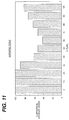
- Figure 11 shows a typical power profile as derived by such an aspheric surface, which could be on either the front or back surface of the lens.
- Figure 11 illustrates a graph for aspheric multifocal lenses of % sphere distance vision as a function of % pupil, wherein the larger percentages of pupil correspond to larger radial distances up to a radius defining the outer circumference of the optic zone of the lens.
Abstract
Description
- The present invention relates generally to concentric annular ring lens designs for astigmatic patients, and more particularly pertains to such lens designs which reduce the sensitivity of the patient to toric axis misalignment, thus reducing the required number of stock keeping units in inventory (the total number of different prescriptions which are maintained in stock and can be prescribed) for a toric product.
- The present invention provides a novel approach for correcting ametropias such as astigmatism, hyperopia and myopia, with a primary correction for astigmatism.
- Currently, toric lenses are manufactured in the prior art with the following design features:
- a. a toric curve on the front or back surface of the lens;
- b. prism ballast and slab-off features on the front surface of the lens;
- c. the non-toric surface is spherical.
-
- These prior art designs correct astigmatism adequately only if the axis of the cylindrical power is accurately aligned with respect to the axis of the astigmatic cornea. A misalignment of the axes (greater than 10°) results in a substantial loss of visual acuity. The primary source of this misalignment in soft hydrogel contact lenses is poor rotational stability.
- In conventional prior art toric lens designs, a single toric surface comprising a major and minor axis is placed in the optical portion of either the front or back surface of the lens. In addition, the axes of the toric lens are usually stabilized in relation to the patient's corneal axes through the use of either a prism ballasted/slab-off feature or a double slab-off feature placed on the front surface of the lens. These features tend to increase the thickness of the resultant lenses and compromise wearing comfort and physiological acceptability.
- Moreover, conventional toric lens designs require a large number of stock keeping units in inventory (the total number of different prescriptions which are maintained in stock and can be prescribed) in order to fit a broad astigmatic patient base. For example, current Frequent Replacement Toric lens products are available in 800 stock keeping units per base curve in inventory (40 spherical powers X 2
cylindrical powers X 10 different cylindrical axis placements). Such a large number of stock keeping units per base curve in inventory is uneconomical to produce and maintain, particularly for a disposable modality product. The required large number of stock keeping units in inventory arises primarily from the need to provide 10 or more different cylindrical axes placements. Furthermore, any significant misalignment of the cylindrical axis with respect to the cylindrical axes of the eye normally results in a significant loss of visual acuity. - In an attempt to reduce the required number of cylindrical axis placements in stock keeping units, Australian Published Patent Application WO 93/03409 combines aspherical surfaces with toric surfaces to accommodate axial misalignment through the increased depth-of-focus provided by aspheres. The use of an aspheric surface enhances the depth-of-field of toric lenses and minimizes the effect of rotational misalignment of the toric lenses. Complex optics such as diffraction optics using echelets or birefringence optics are also disclosed by this published patent application. One disadvantage in using this prior art approach is the difficulty in manufacturing and controlling such complex optics and aspheres. Additionally with aspheric optics, patient anatomical variations have been shown to produce compromised visual acuity. In summary, this prior art approach is undesirable because of the high level of visual unpredictability of aspheric optics on the real world patient base, and because of the difficulty in manufacturing and controlling aspheric and other complex optics.
- Accordingly, it is a primary object of the present invention to provide concentric annular ring lens designs for astigmatic patients which reduce the sensitivity of the patient to toric axis misalignment, thus reducing the required number of stock keeping units maintained in inventory for a toric product. The present invention provides toric lens designs which reduce the number of cylindrical axis placements required to fit astigmatic patients relative to conventional toric lens designs.
- Some embodiments of the present invention eliminate a toric surface, prism ballast and slab-off features, and provide spherical optical powers at the basic prescription Rx spherical power, the cylindrical power prescription Rx, and an intermediate optical power between the spherical and cylindrical optical powers.
- A further object of the subject invention is the provision of concentric annular ring lens designs for astigmatic patients which comprise a multifocal concentric annular ring design on either the front or back surface and a toric curve on the reverse surface to correct for astigmatism.
- The present invention uses alternating concentric annular rings to divide the optical zone of a contact lens into regions having at least two optical powers, a first optical power corresponding to the refractive spherical component of a patient's basic prescription Rx, and a second optical power corresponding to the cylindrical power of a patient's basic prescription Rx, or a portion thereof.
- The present invention provides enhanced and improved visual acuity for astigmatic patients by using concentric annular ring lens designs for the correction of low levels of astigmatism, and also can selectively utilize aspheric curves to enhance vision for higher amounts of astigmatism.
- In accordance with the teachings herein, the present invention provides a multifocus, concentric annular ring lens for astigmatic patients wherein one of the front and back surfaces of the lens defines a toric curve, and the other surface defines a plurality of spherical concentric annular rings having at least one first spherical annular ring corresponding to the patient's basic distance spherical prescription Rx, and at least one second spherical annular ring corresponding to the patient's basic cylindrical prescription Rx, such that the multifocus toric lens is rotationally desensitized because of the enhanced depth-of-field provided by the plurality of concentric annular rings.
- In greater detail, the difference between the optical powers of the first and second spherical annular rings is preferably less than 2.00 diopters. The second spherical annular ring(s) corresponds to a portion of the full cylindrical prescription Rx. The design can also incorporate third spherical annular ring(s) corresponding to an intermediate optical power which is between to the optical powers of the first and second annular rings. The concentric annular rings surround a central disc having the patient's basic spherical distance prescription Rx. Moreover, an aspheric surface can be superposed on the toric curve to enhance the depth-of-field effect of the lens. The lens can be a contact lens, such as a soft hydrogel contact lens, or an intraocular lens.
- The present invention also provides a multifocus, concentric annular ring lens for astigmatic patients wherein one of the front and back surfaces defines a spherical or aspheric curve, and the other of 5 the front and back surfaces defines a plurality of spherical concentric annular rings having at least one first spherical annular ring corresponding to the patient's basic distance prescription Rx, and at least one second spherical annular ring corresponding to the patient's cylindrical prescription Rx.
- In greater detail, the second spherical annular ring(s) corresponds to a portion of the full cylindrical prescription Rx. The design can also incorporate third spherical annular ring(s) corresponding to an intermediate optical power which is between the optical powers of the first and second annular rings. The first annular ring(s) includes a central disc having the patient's basic spherical distance prescription Rx, which is encircled at least one third intermediate power annular ringt, which is encircled at least one second cylindrical power annular ring. The concentric annular rings are preferably on the back surface of the lens, and the front surface can define an aspheric curve to enhance the depth-of-field effect of the lens.
- The present invention also provides a multifocus, concentric annular ring lens for astigmatic patients wherein one of the front and back surfaces defines either a spherical or aspherical curve, and the other surface defines a plurality of respectively either aspheric or spherical concentric annular rings having at least one first annular ring corresponding to the patient's basic distance prescription Rx, and at least one second annular ring corresponding to the patient's cylindrical prescription Rx.
- In greater detail, the lens has a central portion with a distance optical power, an intermediate portion with a substantially equal split of cylindrical and distance optical power, and an outer portion with increased distance optical power. The optical powers between the first and second annular rings is preferably no greater than 2.00 diopters, and the aspheric curve has an elliptical shape with a K value between ∼.05 and ∼.5, such that the ellipses are only slightly departed from spheres.
- The present invention also provides a multifocus, concentric annular ring lens for astigmatic patients wherein one of the front and back surfaces defines a spherical surface corresponding to the patient's basic spherical distance prescription, and the other surface defines a plurality of concentric toric annular rings having at least one first toric annular ring corresponding to the patient's basic distance spherical power correction prescription Rx, and at least one second toric annular ring corresponding to the patient's basic cylindrical prescription Rx (spherical and cylindrical powers combined).
- In greater detail, the second toric annular ring(s) corresponds to a portion of the full cylindrical prescription Rx. The front surface defines the spherical surface and the back surface defines the plurality of toric annular rings wherein the optical power difference between the first and second alternating concentric toric annular rings is no greater than 2.ODD, which provides a sufficient depth-of-focus effect to allow an axial misalignment of up to + or - 20 degrees from the reference axial position.
- The foregoing objects and advantages of the present invention for concentric annular ring lens designs for astigmatism may be more readily understood by one skilled in the art with reference being had to the following detailed description of several preferred embodiments thereof, taken in conjunction with the accompanying drawings wherein like elements are designated by identical reference numerals throughout the several views, and in which:
- Figures 1 and 2 illustrate respectively front plan and side views of a first embodiment of a concentric annular ring lens designed pursuant to the teachings of the present invention which comprises a concentric annular ring spherical front surface having first and second optical powers X and Y and a toric back surface;
- Figures 3 and 4 illustrate respectively front plan and side views of a second embodiment of a concentric annular ring lens similar to the lens of Figures 1 and 2 which includes intermediate spherical optical power rings I in the lens design in addition to the first and second optical spherical powers X and Y;
- Figure 5 illustrates a plan view of the back surface of a third embodiment of a concentric annular ring lens pursuant to the present invention which eliminates the toric surface and utilizes a spherical or aspheric surface on one side of the lens, combined with a multifocal, concentric spherical annular ring surface on the opposite side of the lens;
- Figure 6 illustrates a plan view of the back surface of a further embodiment of a lens design which comprises a spherical front surface corresponding to the patient's basic spherical distance prescription, and a toric back surface consisting of concentric toric annular ring surfaces;
- Figure 7 illustrates a preferred embodiment of the present invention wherein the front surface of the lens comprises a simple toric curve in the optic zone, and the back surface of the lens comprises multiple alternating concentric spherical annular rings;
- Figure 8 is a plan view of a preferred embodiment of a lens design wherein the optic zone of the lens is divided into three zones, an innermost zone which is a spherical disc having the patient's basic distance prescription Rx, a middle zone consisting of one or more annular rings having spherical and cylindrical optical powers, an outer zone consisting of one or more annular rings having predominantly cylindrical optical powers;
- Figure 9 is a plan view of the back surface of an exemplary embodiment of a lens having a concentric multifocal either spherical or aspheric annular ring back surface with respectively either an aspheric or aspherical front surface;
- Figure 10 is a plan view of the front surface of an exemplary embodiment of a lens having a concentric multifocal either spherical or aspheric annular ring front surface with respectively either an aspheric or a spherical back surface;
- Figure 11 shows a typical power profile for aspheric multifocal lenses, and illustrates a graph of % spherical vision as a function of % pupil, wherein the larger percentages of the pupil correspond to larger radial distances of the optic zone of the lens.
-
- Figures 1 and 2 illustrate respectively front plan and side views of a first embodiment of a concentric
annular ring lens 10 designed pursuant to the teachings of the present invention which comprises: - a. a concentric annular ring spherical
front surface 12; - b. a
toric back surface 14; - c. prism ballast and slab-off features 16 on the front surface.
-
- In principle, the two optical spherical powers X and Y of the alternating front surface concentric annular rings X and Y can include first concentric annular rings having a spherical power corresponding to the patient's basic distance prescription Rx, and second spherical annular rings corresponding to the patient's cylindrical prescription Rx, which may correspond to a portion of the patient's cylindrical prescription. The resultant toric lens is rotationally desensitized in the same manner as if the front surface were aspheric with a depth-of-field effect as disclosed in Published Patent Application WO 93/03409.
- Figures 3 and 4 illustrate respectively front plan and side views of a second embodiment of a concentric
annular ring lens 20 pursuant to the present invention similar to thefirst embodiment 10 wherein, in addition to the two optical spherical powers X and Y, intermediate spherical optical power rings I are also included in the lens design. - The following example is illustrative of the principles of operation of the present invention in the embodiments of Figures 1-4.
- For a patient with a prescription Rx of - 3.00/-1.50 X 180 (wherein -3.00D is the patient's basic distance optical power correction, -1.50D is the patient's basic cylindrical optical power correction, with the cylindrical axis specified at 180°), the power on the 90°-270° axis is -4.50D (which is the sum of -3.00D and the full cylindrical -1.50D available on this axis) whereas the power on the 0-180° axis is -3.00D (the cylindrical surface contributes nothing on this axis).
- For the first embodiment, the following are spherical optical power values for x and y:
- For the second embodiment,
- For most patients, visual acuity is acceptable even if the refractive lens is off by 0.5D from the measured refractive power. Therefore, in the above example, the effective ranges of the spherical optical powers are:
- In the first embodiment:
- In the second embodiment:
- It is recognized in the prior art that a patient's brain has the accommodative capability of accepting an in-focus image while disregarding out-of-focus images. Recognizing a patient's basic accommodative capabilities, the above prescriptions should provide acceptable Visual acuity notwithstanding some (10°-20°) misalignment of the axis of the toric lens.
- It is known that for astigmatic subjects, an astigmatic eye will form an image which contains three main regions:
- 1. the spherical power will focus as a line;
- 2. the cylindrical power will also focus as a line, perpendicular to the spherical image line.
- 3. a circular image will focus in between the two focal lines known as the "circle of least confusion", which is at an intermediate optical power intermediate to the spherical and cylindrical optical powers.
-
- Figure 5 illustrates a plan view of the back surface of a third embodiment of a concentric
annular ring lens 50 pursuant to the present invention which eliminates the toric surface and also the prism ballast and slab-off features, and utilizes a spherical oraspheric surface 52 on one side of thelens 50, preferably the front surface although the back surface can be used in alternative embodiments, combined with a multifocal, concentric sphericalannular ring surface 54 on the opposite side of the lens, preferably the back surface although the front surface can be used in alternative embodiments. - In this embodiment, the concentric annular rings in the optic zone of the lens provide at least three different optical powers:
- A-the basic prescription spherical optical power for distance which exists along the cylindrical axis;
- B-the prescription cylindrical 'optical power (spherical and cylindrical powers combined);
- C-an intermediate optical power based upon the best focal point or circle of least confusion of a toric surface. This embodiment utilizes the principle of fitting the spherical equivalent optical power, along with the spherical and cylindrical optical powers.
-
- Several embodiments of the present invention achieve an increased depth-of-focus effect without the use of aspheric surfaces and their attendant complexities and disadvantages. Instead of aspheres, concentric spheres or toric surfaces of small power difference between alternating zones are utilized to provide an increased depth-of-focus effect.
- Figure 6 illustrates a plan view of the back surface of a further embodiment of a
lens design 60 which comprises a sphericalfront surface 62 corresponding to the patient's basic spherical distance prescription, atoric back surface 64 consisting of concentric annular ring toric surfaces 66, having alternating optical powers P1 and P2, and a double slab-off feature 68 to stabilize the lens in either a 90° or 180° axis position. The alternating concentric annular rings correspond to the patient's prescription Rx, and include first annular rings of power P1 corresponding to the patient's distance prescription Rx and second annular rings of a power P2 corresponding to the patient's cylindrical prescription Rx, preferably a portion thereof. The optical power difference between the alternating concentric annular toric rings P1 and P2 is no greater than 2.00D. This small power difference provides a sufficient depth-of-focus effect to allow an axis misalignment of up to + or - 20 degrees from a reference such as either the 90° or 180° position. - Figure 7 illustrates a further preferred embodiment of the present invention wherein the
front surface 72 of thelens 70 comprises a simpletoric optic zone 74 stabilized by a double slab-off feature 76 in the 90° and/or 180° position, and theback surface 78 of the lens comprises multiple alternating concentric spherical annular rings. The alternating concentric annular rings correspond to the patient's prescription Rx, and include first annular rings of power P1 corresponding to the patient's distance prescription Rx and second annular rings of a power P2 corresponding to the patient's cylindrical prescription Rx, preferably a portion thereof. Again, the power difference of the alternating concentric spherical annular rings of the back surface is no greater than 2.00D, which allows an axis misalignment of up to + or - 20 degrees from the reference prescription position. - In either of the previous two embodiments, the number of stock keeping units per base curve maintained in inventory is reduced to 160 (40 spherical powers X 2 cylindrical powers X 2 axes -90°, 180°). Furthermore, the depth-of-focus effect provided by the concentric annular ring lenses allows for axial misalignments without significant loss of visual acuity.
- Several embodiments of the present invention function by alternating spherical power with cylindrical power to provide adequate levels of both powers to the retina of the eye. The actual cylindrical power can be the full cylindrical power or any fraction thereof, ranging from 25% to 100% of the full refractive cylindrical power.
- In some preferred embodiments, the concentric annular ring structures are placed on the back of the contact lens, with the basic spherical distance power in a disc at the center thereof.
- The following TABLE I illustrates several proposed pupil functionalities for this type of multifocal annular ring lens design wherein each zone can include a plurality of annular rings. The subject's pupil is divided into three zones, and the innermost zone is preferred as spherical.
Preferred Pupil Functions Inner Zone Mid Zone Outer Zone Type A: Sphere Equal
(50/50 split)Sphere Type B: Sphere Equal Cylindrical Type C: Sphere Equal Equal Type D: Sphere Cylindrical Sphere Type E: Sphere Cylindrical Equal - In this table, cylindrical means a spherical optical power corresponding to the cylindrical prescription (spherical plus cylindrical powers), or a portion thereof.
- Figure 8 is a plan view of this type of
lens design 80 wherein the optic zone of the lens, which corresponds to a pupil contracted or enlarged under various illumination conditions, is divided into three zones, aninnermost zone 82, amiddle zone 84, anouter zone 86, which are also illustrated in the embodiments of Figures 9 and 10. Theinnermost zone 82 is a spherical disc having the patient's basic distance prescription Rx. Themiddle zone 84 consists of one or more annular rings pursuant to the above table, and theouter zone 86 also consists of one or more annular rings pursuant to the table. Figure 8 illustrates one exemplary designed embodiment of alens design 100 of type B in the table pursuant to the present invention having: an inner spherical zone S, surrounded by an intermediate zone having respective annular rings CSCS, surrounded by an outer zone having only cylindrical power, with a distance curve radius of 8.4 mm; a near curve radius of 8.51173 mm; an intermediate curve radius of 8.39209 mm; and a peripheral curve radius of 9.832 mm. - The present invention relates to concentric annular ring lens designs for the correction of astigmatism which provide enhanced and improved visual acuity. Several of these lens designs have been clinically evaluated on an experimental basis and have been found to be effective in most cases up to cylindrical powers of ∼1.50 DC, with some positive effect up to ∼2.00 DC. The effectiveness of these lens designs can also be enhanced in the range from -1.50 DC to -2.00 DC by combining those concentric annular ring lens designs with aspheric optical surfaces.
Design Types Front Surface Back Surface Asphere Concentric;
spherical ringsSphere Concentric;
aspherical ringsConcentric;
spherical ringsAsphere Concentric;
aspherical ringsSphere - Figure 9 is a plan view of the back surface of an exemplary embodiment of a
lens 90, as listed in Table II, having either a concentric multifocal spherical or aspheric annular ring backsurface 92 with respectively either an aspheric or asphericalfront surface 94. - Figure 10 is a plan view of the front surface of an exemplary embodiment of a
lens 100, as listed in Table II, having either a concentric multifocal spherical or aspheric annular ringfront surface 102 with respectively either an aspheric or aspherical back surface 104. - Previous embodiments herein divide the optic zone of the lens (corresponding to different pupil sizes) into discrete concentric zones with alternating spherical distance and cylindrical optical powers. The arrangement of those power zones could be disposed to provide an optimal split between spherical and cylindrical optical powers, obtained when the central portion of the lens has distance optical power, the intermediate sized pupils have a near equal split and the largest of pupil sizes having an increased distance optical power.
- Aspheric surfaces can be described by the following general equation which is a general conic equation which describes all conics, including spheres, parabolas, ellipses and hyperbola:
- k = 0 for a sphere,
- k = -1 for a parabola,
- 0 > k > -1 for an ellipse,
- k < -1 for a hyperbola.
-
- A lens with a front surface having an asphere combined with a rear surface having concentric annular spherical rings is a preferred embodiment as it is easy to design and implement. Most of the power difference correction for astigmatism is accomplished by the concentric annular ring lens design, and accordingly an asphere providing only a slight boost is required to improve visual acuity. In order to achieve this, a small aspheric K value is required. The K value is less than that required to reduce the blur circle (circle of least confusion) diameter for both spherical and cylindrical powers on their own. An optimal form is an elliptical shape, with a K value between ∼.05 and ∼.5. Thus, the ellipses used herein are only slightly departed from spheres.
- In the case of aspheric rings, either the spherical or the cylindrical rings or both may be aspherized. In that case, the K values also remain between -.05 to -.5.
- The present invention can also repiace the discrete concentric annular bands with a smooth aspheric function. Aspheric in this sense can indicate a conic asphere, a conic asphere with varying eccentricity, or a polynomial function which simulates the functional discrete power split.
- Figure 11 shows a typical power profile as derived by such an aspheric surface, which could be on either the front or back surface of the lens. Figure 11 illustrates a graph for aspheric multifocal lenses of % sphere distance vision as a function of % pupil, wherein the larger percentages of pupil correspond to larger radial distances up to a radius defining the outer circumference of the optic zone of the lens.
- While several embodiments and variations of the present invention for concentric lens designs for astigmatism are described in detail herein, it should be apparent that the disclosure and teachings of the present invention will suggest many alternative designs to those skilled in the art.
Claims (13)
- A multifocus, concentric annular ring lens for astigmatic patients wherein:a. said lens has a front surface and an opposite back surface;b. one of said front and back surfaces defines a toric, spherical or aspheric curve;c. the other of the front and back surfaces defines a plurality of concentric annular rings having at least one first annular ring and at least one second annular ring corresponding to the patient's cylindrical prescription Rx; andd. (i). when said surface in b. is toric, said first annular ring is spherical and corresponds to the patient's basic distance spherical prescription Rx, and said second annular ring is spherical; ord.(ii). when said surface in b. is spherical or aspheric, said first annular ring is spherical and corresponds to the patient's basic distance prescription Rx and said second annular ring is spherical; ord.(iii). when said surface in b. is spherical, said first annular ring is aspheric and corresponds to the patient's basic distance prescription Rx and said second annular ring is aspheric; ord.(iv). when said surface in b. is aspheric, said first annular ring is spherical and corresponds to the patient's basic distance prescription Rx and said second annular ring is spherical; ord.(v). when said surface in b. is spherical and corresponds to the patient's basic spherical distance prescription, said first annular ring is toric and corresponds to the patient's basic spherical correction prescription Rx and said second annular ring is toric.
- The lens of claim 1, wherein the difference between the optical powers of the first and second annular rings is less than 2.0 diopters.
- The lens of claim 1 or claim 2, wherein said second annular ring corresponds to a portion of the full cylindrical prescription Rx.
- The lens of any one of claims 1 to 3, further including at least one third annular ring corresponding to an optical power which is intermediate the optical powers of said first and second annular rings.
- The lens of any one of claims 1 to 4, wherein the concentric annular rings surround a central disc having the patient's basic spherical distance prescription Rx.
- The lens of claims 4 and 5, wherein the third annular ring encircles the central disc and the second annular ring encircles the third annular ring.
- The lens of any one of claims 1 to 6, wherein the concentric annular rings are on the back surface of the lens.
- The lens of any one of claims 1 to 7, using the part (d).(i) arrangement, further including an aspheric surface superposed on the toric curve to enhance the depth-of-field effect of the lens.
- The lens of any one of claims 1 to 7 using the part d.(ii) arrangement, wherein the part b. surface defines an aspheric curve to enhance the depth-of-field effect of the lens.
- The lens of any one of claims 1 to 7, using the part d.(iii) or d.(iv) arrangement, wherein the lens has a central portion with a distance optical power, an intermediate portion with a substantially equal split of cylindrical and distance optical power and an outer portion with increased distance optical power.
- The lens of any one of claims 1 to 7 and 10, using the part d.(iii) or d.(iv) arrangement, wherein each aspheric annular ring has an elliptical shape with a K value between -·05 and -·5 such that the ellipses are only slightly departed from spheres.
- The lens of any one of claims 1 to 7, using the part d.(v) arrangement, wherein each toric annular ring has an aspheric curve having an elliptical shape with a K value between -·05 and -·5 such that the ellipses are only slightly departed from spheres.
- The lens of any one of claims 1 to 7, which is a contact lens, such as a soft hydrogel contact lens, or an intra-ocular lens.
Applications Claiming Priority (3)
| Application Number | Priority Date | Filing Date | Title |
|---|---|---|---|
| US433741 | 1995-05-04 | ||
| US08/433,741 US5652638A (en) | 1995-05-04 | 1995-05-04 | Concentric annular ring lens designs for astigmatism |
| EP96303132A EP0745876B1 (en) | 1995-05-04 | 1996-05-03 | Method of correcting astigmatism using concentric ring lenses |
Related Parent Applications (1)
| Application Number | Title | Priority Date | Filing Date |
|---|---|---|---|
| EP96303132A Division EP0745876B1 (en) | 1995-05-04 | 1996-05-03 | Method of correcting astigmatism using concentric ring lenses |
Publications (2)
| Publication Number | Publication Date |
|---|---|
| EP1376203A2 true EP1376203A2 (en) | 2004-01-02 |
| EP1376203A3 EP1376203A3 (en) | 2004-10-27 |
Family
ID=23721361
Family Applications (2)
| Application Number | Title | Priority Date | Filing Date |
|---|---|---|---|
| EP03077133A Ceased EP1376203A3 (en) | 1995-05-04 | 1996-05-03 | Concentric annular ring lens designs for astigmatism |
| EP96303132A Expired - Lifetime EP0745876B1 (en) | 1995-05-04 | 1996-05-03 | Method of correcting astigmatism using concentric ring lenses |
Family Applications After (1)
| Application Number | Title | Priority Date | Filing Date |
|---|---|---|---|
| EP96303132A Expired - Lifetime EP0745876B1 (en) | 1995-05-04 | 1996-05-03 | Method of correcting astigmatism using concentric ring lenses |
Country Status (18)
| Country | Link |
|---|---|
| US (1) | US5652638A (en) |
| EP (2) | EP1376203A3 (en) |
| JP (1) | JP4198204B2 (en) |
| KR (1) | KR100407734B1 (en) |
| CN (1) | CN1105315C (en) |
| AT (1) | ATE336020T1 (en) |
| AU (1) | AU698529B2 (en) |
| BR (1) | BR9602145B1 (en) |
| CA (1) | CA2175631C (en) |
| DE (1) | DE69636425T2 (en) |
| HU (1) | HUP9601128A3 (en) |
| IL (1) | IL118066A (en) |
| NO (1) | NO961802L (en) |
| NZ (1) | NZ286482A (en) |
| RO (1) | RO117130B1 (en) |
| SG (1) | SG48441A1 (en) |
| TW (1) | TW334518B (en) |
| ZA (1) | ZA963537B (en) |
Cited By (11)
| Publication number | Priority date | Publication date | Assignee | Title |
|---|---|---|---|---|
| US7896916B2 (en) | 2002-11-29 | 2011-03-01 | Amo Groningen B.V. | Multifocal ophthalmic lens |
| US7984990B2 (en) | 2004-10-25 | 2011-07-26 | Abbot Medical Optics Inc. | Ophthalmic lens with multiple phase plates |
| US9335563B2 (en) | 2012-08-31 | 2016-05-10 | Amo Groningen B.V. | Multi-ring lens, systems and methods for extended depth of focus |
| US10085833B2 (en) | 2002-11-29 | 2018-10-02 | Amo Groningen B.V. | Multifocal ophthalmic lens |
| US10624735B2 (en) | 2016-02-09 | 2020-04-21 | Amo Groningen B.V. | Progressive power intraocular lens, and methods of use and manufacture |
| US11156853B2 (en) | 2017-06-28 | 2021-10-26 | Amo Groningen B.V. | Extended range and related intraocular lenses for presbyopia treatment |
| US11262598B2 (en) | 2017-06-28 | 2022-03-01 | Amo Groningen, B.V. | Diffractive lenses and related intraocular lenses for presbyopia treatment |
| US11327210B2 (en) | 2017-06-30 | 2022-05-10 | Amo Groningen B.V. | Non-repeating echelettes and related intraocular lenses for presbyopia treatment |
| US11497599B2 (en) | 2017-03-17 | 2022-11-15 | Amo Groningen B.V. | Diffractive intraocular lenses for extended range of vision |
| US11523897B2 (en) | 2017-06-23 | 2022-12-13 | Amo Groningen B.V. | Intraocular lenses for presbyopia treatment |
| US11844689B2 (en) | 2019-12-30 | 2023-12-19 | Amo Groningen B.V. | Achromatic lenses and lenses having diffractive profiles with irregular width for vision treatment |
Families Citing this family (138)
| Publication number | Priority date | Publication date | Assignee | Title |
|---|---|---|---|---|
| IL117937A0 (en) * | 1995-05-04 | 1996-08-04 | Johnson & Johnson Vision Prod | Combined multifocal toric lens designs |
| HUP9601126A3 (en) * | 1995-05-04 | 1999-10-28 | Johnson & Johnson Vision Prod | Concentric, aspheric, multifocal lens |
| US5864378A (en) * | 1996-05-21 | 1999-01-26 | Allergan | Enhanced monofocal IOL or contact lens |
| GB9716793D0 (en) * | 1997-08-07 | 1997-10-15 | Vista Optics Limited | Contact lens |
| US6457826B1 (en) | 1998-08-06 | 2002-10-01 | John B. W. Lett | Multifocal aspheric lens |
| US6231603B1 (en) | 1998-11-10 | 2001-05-15 | Allergan Sales, Inc. | Accommodating multifocal intraocular lens |
| AU2365300A (en) | 1998-12-16 | 2000-07-03 | Wesley-Jessen Corporation | Multifocal contact lens with aspheric surface |
| US6234629B1 (en) | 1998-12-21 | 2001-05-22 | Johnson & Johnson Vision Care, Inc. | Differential thickness contact lens with compensation for differential shrinkage and method of manufacturing same |
| US6135594A (en) * | 1998-12-21 | 2000-10-24 | Johnson & Johnson Vision Care, Inc. | Toric contact lens with axis offset compensation and method and apparatus for manufacturing same |
| US5988813A (en) | 1998-12-21 | 1999-11-23 | Johnson & Johnson Vision Products, Inc. | Differential thickness contact lens utilizing multiple base curves and method of manufacturing same |
| US6616692B1 (en) | 1999-04-30 | 2003-09-09 | Advanced Medical Optics, Inc. | Intraocular lens combinations |
| US6790232B1 (en) | 1999-04-30 | 2004-09-14 | Advanced Medical Optics, Inc. | Multifocal phakic intraocular lens |
| US6406494B1 (en) | 1999-04-30 | 2002-06-18 | Allergan Sales, Inc. | Moveable intraocular lens |
| US20030060881A1 (en) * | 1999-04-30 | 2003-03-27 | Advanced Medical Optics, Inc. | Intraocular lens combinations |
| US20060238702A1 (en) | 1999-04-30 | 2006-10-26 | Advanced Medical Optics, Inc. | Ophthalmic lens combinations |
| US6599317B1 (en) | 1999-09-17 | 2003-07-29 | Advanced Medical Optics, Inc. | Intraocular lens with a translational zone |
| US6645246B1 (en) | 1999-09-17 | 2003-11-11 | Advanced Medical Optics, Inc. | Intraocular lens with surrounded lens zone |
| US6551354B1 (en) * | 2000-03-09 | 2003-04-22 | Advanced Medical Optics, Inc. | Accommodating intraocular lens |
| US6467903B1 (en) * | 2000-03-31 | 2002-10-22 | Ocular Sciences, Inc. | Contact lens having a uniform horizontal thickness profile |
| US7628485B2 (en) * | 2000-03-31 | 2009-12-08 | Coopervision International Holding Company, Lp | Contact lens having a uniform horizontal thickness profile |
| US6547822B1 (en) | 2000-05-03 | 2003-04-15 | Advanced Medical Optics, Inc. | Opthalmic lens systems |
| US6537317B1 (en) | 2000-05-03 | 2003-03-25 | Advanced Medical Optics, Inc. | Binocular lens systems |
| US6554859B1 (en) | 2000-05-03 | 2003-04-29 | Advanced Medical Optics, Inc. | Accommodating, reduced ADD power multifocal intraocular lenses |
| US6609793B2 (en) * | 2000-05-23 | 2003-08-26 | Pharmacia Groningen Bv | Methods of obtaining ophthalmic lenses providing the eye with reduced aberrations |
| US8020995B2 (en) | 2001-05-23 | 2011-09-20 | Amo Groningen Bv | Methods of obtaining ophthalmic lenses providing the eye with reduced aberrations |
| US6660035B1 (en) | 2000-08-02 | 2003-12-09 | Advanced Medical Optics, Inc. | Accommodating intraocular lens with suspension structure |
| US6582076B1 (en) * | 2000-08-30 | 2003-06-24 | Johnson & Johnson Vision Care, Inc. | Ophthalmic lenses useful in correcting astigmatism and presbyopia |
| US8062361B2 (en) | 2001-01-25 | 2011-11-22 | Visiogen, Inc. | Accommodating intraocular lens system with aberration-enhanced performance |
| US6786934B2 (en) * | 2001-01-25 | 2004-09-07 | Visiogen, Inc. | Biasing element for intraocular lens system |
| US7780729B2 (en) | 2004-04-16 | 2010-08-24 | Visiogen, Inc. | Intraocular lens |
| US20030078657A1 (en) * | 2001-01-25 | 2003-04-24 | Gholam-Reza Zadno-Azizi | Materials for use in accommodating intraocular lens system |
| US20030078658A1 (en) | 2001-01-25 | 2003-04-24 | Gholam-Reza Zadno-Azizi | Single-piece accomodating intraocular lens system |
| US20120016349A1 (en) | 2001-01-29 | 2012-01-19 | Amo Development, Llc. | Hybrid ophthalmic interface apparatus and method of interfacing a surgical laser with an eye |
| US6576012B2 (en) | 2001-03-28 | 2003-06-10 | Advanced Medical Optics, Inc. | Binocular lens systems |
| US6638305B2 (en) | 2001-05-15 | 2003-10-28 | Advanced Medical Optics, Inc. | Monofocal intraocular lens convertible to multifocal intraocular lens |
| US6533416B1 (en) | 2001-07-20 | 2003-03-18 | Ocular Sciences, Inc. | Contact or intraocular lens and method for its preparation |
| US7763069B2 (en) | 2002-01-14 | 2010-07-27 | Abbott Medical Optics Inc. | Accommodating intraocular lens with outer support structure |
| JP3860041B2 (en) | 2002-01-23 | 2006-12-20 | 株式会社メニコン | Contact lens and contact lens design method |
| US6923540B2 (en) * | 2002-07-31 | 2005-08-02 | Novartis Ag | Toric multifocal contact lenses |
| AU2003260369A1 (en) | 2002-08-06 | 2004-02-25 | Novartis Ag | Contact lenses |
| US6972033B2 (en) * | 2002-08-26 | 2005-12-06 | Advanced Medical Optics, Inc. | Accommodating intraocular lens assembly with multi-functional capsular bag ring |
| US20040082993A1 (en) | 2002-10-25 | 2004-04-29 | Randall Woods | Capsular intraocular lens implant having a refractive liquid therein |
| US7662180B2 (en) | 2002-12-05 | 2010-02-16 | Abbott Medical Optics Inc. | Accommodating intraocular lens and method of manufacture thereof |
| US6986578B2 (en) * | 2003-01-30 | 2006-01-17 | Johnson & Johnson Vision Care, Inc. | Multifocal ophthalmic lenses |
| CA2526076C (en) | 2003-05-21 | 2013-08-06 | Novartis Ag | Contact lenses |
| US7628810B2 (en) | 2003-05-28 | 2009-12-08 | Acufocus, Inc. | Mask configured to maintain nutrient transport without producing visible diffraction patterns |
| US6939005B2 (en) * | 2003-08-20 | 2005-09-06 | Johnson & Johnson Vision Care Inc. | Rotationally stabilized contact lenses |
| US7036930B2 (en) | 2003-10-27 | 2006-05-02 | Johnson & Johnson Vision Care, Inc. | Methods for reducing corneal staining in contact lens wearers |
| US20050131535A1 (en) | 2003-12-15 | 2005-06-16 | Randall Woods | Intraocular lens implant having posterior bendable optic |
| US6988800B2 (en) * | 2004-01-06 | 2006-01-24 | St. Shine Optical Co., Ltd. | Toric contact lens with meniscus-shaped flattened top and bottom zones for dynamic stabilization |
| US7201480B2 (en) | 2004-05-20 | 2007-04-10 | Johnson & Johnson Vision Care, Inc. | Methods for rotationally stabilizing contact lenses |
| BRPI0518378A2 (en) * | 2004-10-25 | 2008-11-18 | Advanced Medical Optics Inc | ophthalmic lens with multiple phase plates |
| SG177132A1 (en) | 2005-02-14 | 2012-01-30 | Johnson & Johnson Vision Care | A comfortable ophthalmic device and methods of its production |
| US9636213B2 (en) | 2005-09-30 | 2017-05-02 | Abbott Medical Optics Inc. | Deformable intraocular lenses and lens systems |
| US9052529B2 (en) | 2006-02-10 | 2015-06-09 | Johnson & Johnson Vision Care, Inc. | Comfortable ophthalmic device and methods of its production |
| AR062067A1 (en) * | 2006-07-17 | 2008-10-15 | Novartis Ag | TORICAS CONTACT LENSES WITH CONTROLLED OPTICAL POWER PROFILE |
| EP2629138A3 (en) * | 2006-10-10 | 2013-10-23 | Novartis AG | A contact lens for preventing myopia |
| AU2007338100B2 (en) | 2006-12-22 | 2014-01-30 | Amo Groningen Bv | Accommodating intraocular lens, lens system and frame therefor |
| US7713299B2 (en) | 2006-12-29 | 2010-05-11 | Abbott Medical Optics Inc. | Haptic for accommodating intraocular lens |
| US20080161914A1 (en) | 2006-12-29 | 2008-07-03 | Advanced Medical Optics, Inc. | Pre-stressed haptic for accommodating intraocular lens |
| WO2008083283A2 (en) | 2006-12-29 | 2008-07-10 | Advanced Medical Optics, Inc. | Multifocal accommodating intraocular lens |
| US20080269882A1 (en) * | 2007-04-30 | 2008-10-30 | Alcon Universal Ltd. | Intraocular lens with asymmetric optics |
| US20090228101A1 (en) * | 2007-07-05 | 2009-09-10 | Visiogen, Inc. | Intraocular lens with post-implantation adjustment capabilities |
| US8974526B2 (en) | 2007-08-27 | 2015-03-10 | Amo Groningen B.V. | Multizonal lens with extended depth of focus |
| US8747466B2 (en) | 2007-08-27 | 2014-06-10 | Amo Groningen, B.V. | Intraocular lens having extended depth of focus |
| US20090062911A1 (en) * | 2007-08-27 | 2009-03-05 | Amo Groningen Bv | Multizonal lens with extended depth of focus |
| US9216080B2 (en) * | 2007-08-27 | 2015-12-22 | Amo Groningen B.V. | Toric lens with decreased sensitivity to cylinder power and rotation and method of using the same |
| US8740978B2 (en) * | 2007-08-27 | 2014-06-03 | Amo Regional Holdings | Intraocular lens having extended depth of focus |
| ATE523810T1 (en) * | 2008-02-15 | 2011-09-15 | Amo Regional Holdings | SYSTEM, GLASS LENS AND METHOD FOR EXPANDING THE DEPTH OF FOCUS |
| US8439498B2 (en) | 2008-02-21 | 2013-05-14 | Abbott Medical Optics Inc. | Toric intraocular lens with modified power characteristics |
| US7780290B2 (en) * | 2008-02-21 | 2010-08-24 | Abbott Medical Optics Inc. | Toric intraocular lens with spatially-variant astigmatism |
| US8646908B2 (en) | 2008-03-04 | 2014-02-11 | Johnson & Johnson Vision Care, Inc. | Rotationally stabilized contact lenses and methods for their design |
| US8034108B2 (en) | 2008-03-28 | 2011-10-11 | Abbott Medical Optics Inc. | Intraocular lens having a haptic that includes a cap |
| US7753521B2 (en) * | 2008-03-31 | 2010-07-13 | Johnson & Johnson Vision Care, Inc. | Lenses for the correction of presbyopia and methods of designing the lenses |
| EP2265216B1 (en) * | 2008-04-02 | 2016-10-12 | Junzhong Liang | Methods and devices for refractive corrections of presbyopia |
| MX2010011466A (en) * | 2008-04-18 | 2011-05-30 | Novartis Ag | Myopia control means. |
| US8231219B2 (en) * | 2008-04-24 | 2012-07-31 | Amo Groningen B.V. | Diffractive lens exhibiting enhanced optical performance |
| US7871162B2 (en) * | 2008-04-24 | 2011-01-18 | Amo Groningen B.V. | Diffractive multifocal lens having radially varying light distribution |
| US8862447B2 (en) | 2010-04-30 | 2014-10-14 | Amo Groningen B.V. | Apparatus, system and method for predictive modeling to design, evaluate and optimize ophthalmic lenses |
| US8444267B2 (en) | 2009-12-18 | 2013-05-21 | Amo Groningen B.V. | Ophthalmic lens, systems and methods with angular varying phase delay |
| BRPI0916627B1 (en) * | 2008-08-11 | 2019-10-08 | Novartis Ag | Contact Lens to Prevent Myopia or Reduce Myopia Progression |
| US20100053548A1 (en) * | 2008-08-28 | 2010-03-04 | Perez Jose L | Toric Contact Lenses |
| US9649032B2 (en) | 2008-12-01 | 2017-05-16 | Perfect Vision Technology (Hk) Ltd. | Systems and methods for remote measurement of the eyes and delivering of sunglasses and eyeglasses |
| EP2369972B1 (en) * | 2008-12-01 | 2017-06-07 | Perfect Vision Technology (HK) Ltd. | Methods and devices for refractive correction of eyes |
| US9277863B2 (en) | 2008-12-01 | 2016-03-08 | Perfect Vision Technology (Hk) Ltd. | Methods and systems for automated measurement of the eyes and delivering of sunglasses and eyeglasses |
| CA2743191A1 (en) * | 2008-12-19 | 2010-07-15 | Novartis Ag | Correction of peripheral defocus of an eye and control of refractive error development |
| CA2766655C (en) | 2009-06-26 | 2017-10-10 | Abbott Medical Optics Inc. | Accommodating intraocular lenses |
| CA2770074C (en) | 2009-08-03 | 2017-09-05 | Abbott Medical Optics Inc. | Intraocular lens for providing accomodative vision |
| EP2464311B1 (en) | 2009-08-13 | 2017-11-15 | AcuFocus, Inc. | Masked intraocular implants and lenses |
| US10004593B2 (en) | 2009-08-13 | 2018-06-26 | Acufocus, Inc. | Intraocular lens with elastic mask |
| US8480229B2 (en) | 2009-12-17 | 2013-07-09 | Johnson & Johnson Vision Care, Inc. | Method for stabilizing contact lenses |
| US8322851B2 (en) | 2009-12-17 | 2012-12-04 | Johnson & Johnson Vision Care, Inc. | Stabilized contact lenses |
| US20110149229A1 (en) | 2009-12-17 | 2011-06-23 | Pierre Gerligand | Contact lenses with stabilization features |
| US8403479B2 (en) | 2009-12-17 | 2013-03-26 | Johnson & Johnson Vision Care, Inc. | Contact lens eye model |
| US20110149230A1 (en) | 2009-12-17 | 2011-06-23 | Menezes Edgar V | Stabilization of contact lenses |
| US8439499B2 (en) | 2009-12-17 | 2013-05-14 | Johnson & Johnson Vision Care, Inc. | Method for producing stabilized contact lenses |
| US8256896B2 (en) | 2010-02-25 | 2012-09-04 | Abbott Medical Optic Inc. | Toric optic for ophthalmic use |
| EP2560693A1 (en) | 2010-04-23 | 2013-02-27 | Johnson & Johnson Vision Care, Inc. | Method of improving lens rotation |
| DE102010018436B4 (en) * | 2010-04-27 | 2017-02-09 | Carl Zeiss Meditec Ag | Multifocal eye lens |
| EP2646872A1 (en) | 2010-12-01 | 2013-10-09 | AMO Groningen B.V. | A multifocal lens having an optical add power progression, and a system and method of providing same |
| US9931200B2 (en) | 2010-12-17 | 2018-04-03 | Amo Groningen B.V. | Ophthalmic devices, systems, and methods for optimizing peripheral vision |
| US8894204B2 (en) | 2010-12-17 | 2014-11-25 | Abbott Medical Optics Inc. | Ophthalmic lens, systems and methods having at least one rotationally asymmetric diffractive structure |
| JP6046160B2 (en) | 2011-12-02 | 2016-12-14 | アキュフォーカス・インコーポレーテッド | Ophthalmic mask with selective spectral transmission |
| CN102436075B (en) * | 2011-12-23 | 2013-04-10 | 苏州大学 | Progressive addition lens with large visual areas and low astigmatism |
| US9046698B2 (en) * | 2012-02-28 | 2015-06-02 | Johnson & Johnson Vision Care, Inc. | Multi-axis lens design for astigmatism |
| AU2015268675B2 (en) * | 2012-02-28 | 2016-09-29 | Johnson & Johnson Vision Care, Inc. | Multi-axis lens design for astigmatism |
| US9084674B2 (en) | 2012-05-02 | 2015-07-21 | Abbott Medical Optics Inc. | Intraocular lens with shape changing capability to provide enhanced accomodation and visual acuity |
| US9414906B2 (en) | 2012-09-07 | 2016-08-16 | BeautiEyes, LLC | Eye aperture enhancing prosthesis and method |
| US9132005B2 (en) | 2012-09-07 | 2015-09-15 | BeautiEyes, LLC | Eye aperture enhancing prosthesis and method |
| US9995947B2 (en) | 2012-09-07 | 2018-06-12 | BeautiEyes, LLC | Prosthesis and method for widening the palpebral fissure of an individual's eye |
| CA2877203A1 (en) | 2012-12-04 | 2014-06-12 | Amo Groningen B.V. | Lenses, systems and methods for providing binocular customized treatments to correct presbyopia |
| WO2014143585A1 (en) | 2013-03-11 | 2014-09-18 | Abbott Medical Optics Inc. | Intraocular lens that matches an image surface to a retinal shape, and method of designing same |
| AU2015313934B2 (en) | 2014-03-10 | 2019-12-05 | Amo Groningen B.V. | Dual-optic intraocular lens that improves overall vision where there is a local loss of retinal function |
| CA2946356C (en) | 2014-04-21 | 2022-09-20 | Amo Groningen B.V. | Ophthalmic devices, system and methods that improve peripheral vision |
| EP3359987B1 (en) | 2015-10-05 | 2024-02-28 | AcuFocus, Inc. | Methods of molding intraocular lenses |
| JP7055747B2 (en) | 2015-11-24 | 2022-04-18 | アキュフォーカス・インコーポレーテッド | Toric small aperture intraocular lens with extended depth of focus |
| US11083566B2 (en) | 2016-02-29 | 2021-08-10 | Alcon Inc. | Ophthalmic lens having an extended depth of focus |
| WO2017153843A1 (en) | 2016-03-11 | 2017-09-14 | Amo Groningen B.V. | Intraocular lenses that improve peripheral vision |
| WO2017165695A1 (en) | 2016-03-23 | 2017-09-28 | Abbott Medical Optics Inc. | Ophthalmic apparatus with corrective meridians having extended tolerance band by modifying refractive powers in uniform meridian distribution |
| EP3432768B1 (en) | 2016-03-23 | 2020-04-29 | Johnson & Johnson Surgical Vision, Inc. | Power calculator for an ophthalmic apparatus with corrective meridians having extended tolerance or operation band |
| EP3445288B1 (en) | 2016-04-19 | 2020-11-04 | AMO Groningen B.V. | Ophthalmic devices, system and methods that improve peripheral vision |
| US10444539B2 (en) | 2016-05-11 | 2019-10-15 | Perect Vision Technology (Hk) Ltd. | Methods and systems for determining refractive corrections of human eyes for eyeglasses |
| JP6646531B2 (en) * | 2016-06-20 | 2020-02-14 | Hoya株式会社 | Contact lens and method of manufacturing the same |
| WO2018037356A1 (en) | 2016-08-23 | 2018-03-01 | Medicem Ophthalmic (Cy) Limited | Ophthalmic lenses with aspheric optical surfaces and method for their manufacture |
| WO2018078439A2 (en) | 2016-10-25 | 2018-05-03 | Amo Groningen B.V. | Realistic eye models to design and evaluate intraocular lenses for a large field of view |
| US10739227B2 (en) | 2017-03-23 | 2020-08-11 | Johnson & Johnson Surgical Vision, Inc. | Methods and systems for measuring image quality |
| US20190064543A1 (en) * | 2017-08-30 | 2019-02-28 | Johnson & Johnson Vision Care, Inc. | Atoric Surfaces to Minimize Secondary Astigmatism in Contact Lenses for the Correction of Astigmatism |
| EP3681438A1 (en) | 2017-09-11 | 2020-07-22 | AMO Groningen B.V. | Methods and apparatuses to increase intraocular lenses positional stability |
| CA3082053A1 (en) | 2017-11-30 | 2019-06-06 | Amo Groningen B.V. | Intraocular lenses that improve post-surgical spectacle independent and methods of manufacturing thereof |
| US10901237B2 (en) * | 2018-01-22 | 2021-01-26 | Johnson & Johnson Vision Care, Inc. | Ophthalmic lens with an optically non-coaxial zone for myopia control |
| US11789292B2 (en) | 2018-01-22 | 2023-10-17 | Johnson & Johnson Vision Care, Inc. | Ophthalmic lens with an optically non-coaxial zone for myopia control |
| US11768386B2 (en) | 2018-01-22 | 2023-09-26 | Johnson & Johnson Vision Care, Inc. | Ophthalmic lens with an optically non-coaxial zone for myopia control |
| DE212019000205U1 (en) | 2018-03-01 | 2020-10-07 | Essilor International | Lens element |
| US11364110B2 (en) | 2018-05-09 | 2022-06-21 | Acufocus, Inc. | Intraocular implant with removable optic |
| US11112621B2 (en) | 2019-02-19 | 2021-09-07 | Johnson & Johnson Vision Care, Inc. | Optical device with desensitized rotational angular alignment for astigmatism correction |
| US11106056B2 (en) | 2019-03-28 | 2021-08-31 | Aizhong Zhang | Subzonal multifocal diffractive lens |
| US11886046B2 (en) | 2019-12-30 | 2024-01-30 | Amo Groningen B.V. | Multi-region refractive lenses for vision treatment |
| KR102458051B1 (en) * | 2021-12-31 | 2022-10-24 | 주식회사 비에스코퍼레이션 | Slap-off structure of toric lens |
Citations (4)
| Publication number | Priority date | Publication date | Assignee | Title |
|---|---|---|---|---|
| US5125729A (en) * | 1991-05-03 | 1992-06-30 | Les Laboratoires Opti-Centre Inc. | Multifocal contact lens |
| WO1993003409A1 (en) * | 1991-08-09 | 1993-02-18 | Capricornia Contact Lens Pty. Ltd. | Toric lens with axis mislocation latitude |
| EP0601846A1 (en) * | 1992-12-09 | 1994-06-15 | JOHNSON & JOHNSON VISION PRODUCTS, INC. | Pupil-tuned multifocal ophthalmic lens |
| EP0614105A2 (en) * | 1990-01-29 | 1994-09-07 | WJ Acquisition Corp. | Contact lens for correcting of astigmatism |
Family Cites Families (7)
| Publication number | Priority date | Publication date | Assignee | Title |
|---|---|---|---|---|
| US3623800A (en) * | 1969-10-16 | 1971-11-30 | David Volk | Ophthalmic lens of changing power |
| US4324461A (en) * | 1979-11-26 | 1982-04-13 | Salvatori Ophthalmics, Inc. | Contact lens for non-rotational orientation |
| US4580882A (en) * | 1983-04-21 | 1986-04-08 | Benjamin Nuchman | Continuously variable contact lens |
| US4932970A (en) * | 1988-05-17 | 1990-06-12 | Allergan, Inc. | Ophthalmic lens |
| US5050095A (en) * | 1988-05-31 | 1991-09-17 | Honeywell Inc. | Neural network auto-associative memory with two rules for varying the weights |
| FR2642855B1 (en) * | 1989-02-06 | 1991-05-17 | Essilor Int | OPTICAL LENS FOR THE CORRECTION OF ASTIGMATISM |
| US5220359A (en) * | 1990-07-24 | 1993-06-15 | Johnson & Johnson Vision Products, Inc. | Lens design method and resulting aspheric lens |
-
1995
- 1995-05-04 US US08/433,741 patent/US5652638A/en not_active Expired - Lifetime
-
1996
- 1996-04-29 HU HU9601128A patent/HUP9601128A3/en unknown
- 1996-04-29 IL IL118066A patent/IL118066A/en active IP Right Grant
- 1996-04-30 NZ NZ286482A patent/NZ286482A/en unknown
- 1996-05-02 JP JP14637496A patent/JP4198204B2/en not_active Expired - Lifetime
- 1996-05-02 CA CA002175631A patent/CA2175631C/en not_active Expired - Lifetime
- 1996-05-03 DE DE69636425T patent/DE69636425T2/en not_active Expired - Lifetime
- 1996-05-03 EP EP03077133A patent/EP1376203A3/en not_active Ceased
- 1996-05-03 AU AU52068/96A patent/AU698529B2/en not_active Expired
- 1996-05-03 EP EP96303132A patent/EP0745876B1/en not_active Expired - Lifetime
- 1996-05-03 KR KR1019960014337A patent/KR100407734B1/en not_active IP Right Cessation
- 1996-05-03 NO NO961802A patent/NO961802L/en unknown
- 1996-05-03 ZA ZA9603537A patent/ZA963537B/en unknown
- 1996-05-03 AT AT96303132T patent/ATE336020T1/en not_active IP Right Cessation
- 1996-05-03 RO RO96-00921A patent/RO117130B1/en unknown
- 1996-05-03 BR BRPI9602145-4A patent/BR9602145B1/en not_active IP Right Cessation
- 1996-05-04 CN CN96108965A patent/CN1105315C/en not_active Expired - Lifetime
- 1996-05-04 SG SG1996009722A patent/SG48441A1/en unknown
- 1996-05-27 TW TW085106253A patent/TW334518B/en not_active IP Right Cessation
Patent Citations (4)
| Publication number | Priority date | Publication date | Assignee | Title |
|---|---|---|---|---|
| EP0614105A2 (en) * | 1990-01-29 | 1994-09-07 | WJ Acquisition Corp. | Contact lens for correcting of astigmatism |
| US5125729A (en) * | 1991-05-03 | 1992-06-30 | Les Laboratoires Opti-Centre Inc. | Multifocal contact lens |
| WO1993003409A1 (en) * | 1991-08-09 | 1993-02-18 | Capricornia Contact Lens Pty. Ltd. | Toric lens with axis mislocation latitude |
| EP0601846A1 (en) * | 1992-12-09 | 1994-06-15 | JOHNSON & JOHNSON VISION PRODUCTS, INC. | Pupil-tuned multifocal ophthalmic lens |
Cited By (21)
| Publication number | Priority date | Publication date | Assignee | Title |
|---|---|---|---|---|
| US8529623B2 (en) | 2002-11-29 | 2013-09-10 | Amo Groningen B.V. | Multifocal ophthalmic lens |
| US8906089B2 (en) | 2002-11-29 | 2014-12-09 | Amo Groningen B.V. | Multifocal ophthalmic lens |
| US9636214B2 (en) | 2002-11-29 | 2017-05-02 | Amo Groningen B.V. | Multifocal ophthalmic lens |
| US10085833B2 (en) | 2002-11-29 | 2018-10-02 | Amo Groningen B.V. | Multifocal ophthalmic lens |
| US7896916B2 (en) | 2002-11-29 | 2011-03-01 | Amo Groningen B.V. | Multifocal ophthalmic lens |
| US7984990B2 (en) | 2004-10-25 | 2011-07-26 | Abbot Medical Optics Inc. | Ophthalmic lens with multiple phase plates |
| US8157374B2 (en) | 2004-10-25 | 2012-04-17 | Abbott Medical Optics Inc. | Ophthalmic lens with multiple phase plates |
| US8506075B2 (en) | 2004-10-25 | 2013-08-13 | Abbott Medical Optics Inc. | Ophthalmic lens with multiple phase plates |
| US10197815B2 (en) | 2008-05-13 | 2019-02-05 | Amo Groningen B.V. | Multi-ring lens, systems and methods for extended depth of focus |
| US11022815B2 (en) | 2012-08-31 | 2021-06-01 | Amo Groningen B.V. | Multi-ring lens, systems and methods for extended depth of focus |
| US9335563B2 (en) | 2012-08-31 | 2016-05-10 | Amo Groningen B.V. | Multi-ring lens, systems and methods for extended depth of focus |
| US10624735B2 (en) | 2016-02-09 | 2020-04-21 | Amo Groningen B.V. | Progressive power intraocular lens, and methods of use and manufacture |
| US11116624B2 (en) | 2016-02-09 | 2021-09-14 | Amo Groningen B.V. | Progressive power intraocular lens, and methods of use and manufacture |
| US11497599B2 (en) | 2017-03-17 | 2022-11-15 | Amo Groningen B.V. | Diffractive intraocular lenses for extended range of vision |
| US11523897B2 (en) | 2017-06-23 | 2022-12-13 | Amo Groningen B.V. | Intraocular lenses for presbyopia treatment |
| US11156853B2 (en) | 2017-06-28 | 2021-10-26 | Amo Groningen B.V. | Extended range and related intraocular lenses for presbyopia treatment |
| US11262598B2 (en) | 2017-06-28 | 2022-03-01 | Amo Groningen, B.V. | Diffractive lenses and related intraocular lenses for presbyopia treatment |
| US11573433B2 (en) | 2017-06-28 | 2023-02-07 | Amo Groningen B.V. | Extended range and related intraocular lenses for presbyopia treatment |
| US11914229B2 (en) | 2017-06-28 | 2024-02-27 | Amo Groningen B.V. | Diffractive lenses and related intraocular lenses for presbyopia treatment |
| US11327210B2 (en) | 2017-06-30 | 2022-05-10 | Amo Groningen B.V. | Non-repeating echelettes and related intraocular lenses for presbyopia treatment |
| US11844689B2 (en) | 2019-12-30 | 2023-12-19 | Amo Groningen B.V. | Achromatic lenses and lenses having diffractive profiles with irregular width for vision treatment |
Also Published As
| Publication number | Publication date |
|---|---|
| CN1105315C (en) | 2003-04-09 |
| NO961802L (en) | 1996-11-05 |
| KR100407734B1 (en) | 2004-04-13 |
| SG48441A1 (en) | 1998-04-17 |
| AU5206896A (en) | 1996-11-14 |
| DE69636425D1 (en) | 2006-09-21 |
| CA2175631A1 (en) | 1996-11-05 |
| DE69636425T2 (en) | 2006-12-28 |
| ATE336020T1 (en) | 2006-09-15 |
| CN1162748A (en) | 1997-10-22 |
| MX9601680A (en) | 1997-07-31 |
| EP0745876B1 (en) | 2006-08-09 |
| BR9602145A (en) | 1998-06-30 |
| CA2175631C (en) | 2001-02-13 |
| TW334518B (en) | 1998-06-21 |
| EP0745876A3 (en) | 1998-11-04 |
| US5652638A (en) | 1997-07-29 |
| JP4198204B2 (en) | 2008-12-17 |
| HUP9601128A2 (en) | 1997-08-28 |
| HU9601128D0 (en) | 1996-06-28 |
| ZA963537B (en) | 1997-11-03 |
| AU698529B2 (en) | 1998-10-29 |
| HUP9601128A3 (en) | 1999-10-28 |
| EP1376203A3 (en) | 2004-10-27 |
| NO961802D0 (en) | 1996-05-03 |
| KR960040328A (en) | 1996-12-17 |
| EP0745876A2 (en) | 1996-12-04 |
| JPH0915541A (en) | 1997-01-17 |
| IL118066A (en) | 1998-06-15 |
| BR9602145B1 (en) | 2009-05-05 |
| NZ286482A (en) | 1998-11-25 |
| IL118066A0 (en) | 1996-08-04 |
| RO117130B1 (en) | 2001-10-30 |
Similar Documents
| Publication | Publication Date | Title |
|---|---|---|
| US5652638A (en) | Concentric annular ring lens designs for astigmatism | |
| US5847802A (en) | Concentric annular ring lens designs for astigmatic presbyopes | |
| US5796462A (en) | Aspheric toric lens designs | |
| TWI709788B (en) | Multifocal ophthalmic lens | |
| US5805260A (en) | Combined multifocal toric lens designs | |
| US6582076B1 (en) | Ophthalmic lenses useful in correcting astigmatism and presbyopia | |
| US5929969A (en) | Multifocal ophthalmic lens | |
| AU2001286764A1 (en) | Ophthalmic lenses useful in correcting astigmatism and presbyopia | |
| JPH0947463A (en) | Multi-focus lens which is equipped with intermediate opticalrefracting power | |
| EP0690997A1 (en) | Contact lens designed to accommodate and correct for the effects of presbyopia | |
| EP0742464A2 (en) | Multifocal ophthalmic lens | |
| CN114706234A (en) | Ring focus spectacle lens for controlling myopia progression and method of manufacturing the same | |
| MXPA96001680A (en) | Designs of ring lens anular, concentrical for the astigmati | |
| MXPA96001668A (en) | Designs of ring lens concentrated annular parapresbiopes astigmati | |
| MXPA96001670A (en) | Multifo multifo concentric ring lens | |
| MXPA96001673A (en) | Multifo oftalmico lens | |
| MXPA96001667A (en) | Designs of torica lens, aesfer |
Legal Events
| Date | Code | Title | Description |
|---|---|---|---|
| PUAI | Public reference made under article 153(3) epc to a published international application that has entered the european phase |
Free format text: ORIGINAL CODE: 0009012 |
|
| AC | Divisional application: reference to earlier application |
Ref document number: 0745876 Country of ref document: EP Kind code of ref document: P |
|
| AK | Designated contracting states |
Kind code of ref document: A2 Designated state(s): AT BE CH DE DK ES FI FR GB GR IE IT LI NL PT SE |
|
| AX | Request for extension of the european patent |
Extension state: SI |
|
| RIN1 | Information on inventor provided before grant (corrected) |
Inventor name: MENEZES, EDGAR V. Inventor name: ROFFMAN, JEFFREY H. |
|
| REG | Reference to a national code |
Ref country code: HK Ref legal event code: DE Ref document number: 1059648 Country of ref document: HK |
|
| PUAL | Search report despatched |
Free format text: ORIGINAL CODE: 0009013 |
|
| AK | Designated contracting states |
Kind code of ref document: A3 Designated state(s): AT BE CH DE DK ES FI FR GB GR IE IT LI NL PT SE |
|
| AX | Request for extension of the european patent |
Extension state: SI |
|
| RIC1 | Information provided on ipc code assigned before grant |
Ipc: 7G 02C 7/04 B Ipc: 7G 02B 7/06 A |
|
| 17P | Request for examination filed |
Effective date: 20050427 |
|
| AKX | Designation fees paid |
Designated state(s): AT BE CH DE DK ES FI FR GB GR IE IT LI NL PT SE |
|
| 17Q | First examination report despatched |
Effective date: 20061227 |
|
| APBK | Appeal reference recorded |
Free format text: ORIGINAL CODE: EPIDOSNREFNE |
|
| APBN | Date of receipt of notice of appeal recorded |
Free format text: ORIGINAL CODE: EPIDOSNNOA2E |
|
| APBR | Date of receipt of statement of grounds of appeal recorded |
Free format text: ORIGINAL CODE: EPIDOSNNOA3E |
|
| APAF | Appeal reference modified |
Free format text: ORIGINAL CODE: EPIDOSCREFNE |
|
| APBX | Invitation to file observations in appeal sent |
Free format text: ORIGINAL CODE: EPIDOSNOBA2E |
|
| APBT | Appeal procedure closed |
Free format text: ORIGINAL CODE: EPIDOSNNOA9E |
|
| STAA | Information on the status of an ep patent application or granted ep patent |
Free format text: STATUS: THE APPLICATION HAS BEEN REFUSED |
|
| 18R | Application refused |
Effective date: 20141014 |
|
| REG | Reference to a national code |
Ref country code: HK Ref legal event code: WD Ref document number: 1059648 Country of ref document: HK |