EP1376165A1 - Multilayer optical fiber sheet, optical fiber sheet fabricating method, and optical fiber sheet - Google Patents
Multilayer optical fiber sheet, optical fiber sheet fabricating method, and optical fiber sheet Download PDFInfo
- Publication number
- EP1376165A1 EP1376165A1 EP02714504A EP02714504A EP1376165A1 EP 1376165 A1 EP1376165 A1 EP 1376165A1 EP 02714504 A EP02714504 A EP 02714504A EP 02714504 A EP02714504 A EP 02714504A EP 1376165 A1 EP1376165 A1 EP 1376165A1
- Authority
- EP
- European Patent Office
- Prior art keywords
- optical fiber
- sheet
- optical
- layer
- disposed
- Prior art date
- Legal status (The legal status is an assumption and is not a legal conclusion. Google has not performed a legal analysis and makes no representation as to the accuracy of the status listed.)
- Granted
Links
Images




Classifications
-
- G—PHYSICS
- G02—OPTICS
- G02B—OPTICAL ELEMENTS, SYSTEMS OR APPARATUS
- G02B6/00—Light guides; Structural details of arrangements comprising light guides and other optical elements, e.g. couplings
- G02B6/24—Coupling light guides
- G02B6/36—Mechanical coupling means
- G02B6/3628—Mechanical coupling means for mounting fibres to supporting carriers
- G02B6/3664—2D cross sectional arrangements of the fibres
- G02B6/3676—Stacked arrangement
-
- G—PHYSICS
- G02—OPTICS
- G02B—OPTICAL ELEMENTS, SYSTEMS OR APPARATUS
- G02B6/00—Light guides; Structural details of arrangements comprising light guides and other optical elements, e.g. couplings
- G02B6/24—Coupling light guides
- G02B6/36—Mechanical coupling means
- G02B6/3608—Fibre wiring boards, i.e. where fibres are embedded or attached in a pattern on or to a substrate, e.g. flexible sheets
-
- G—PHYSICS
- G02—OPTICS
- G02B—OPTICAL ELEMENTS, SYSTEMS OR APPARATUS
- G02B6/00—Light guides; Structural details of arrangements comprising light guides and other optical elements, e.g. couplings
- G02B6/24—Coupling light guides
- G02B6/36—Mechanical coupling means
- G02B6/3628—Mechanical coupling means for mounting fibres to supporting carriers
- G02B6/368—Mechanical coupling means for mounting fibres to supporting carriers with pitch conversion between input and output plane, e.g. for increasing packing density
Definitions
- the present invention relates to a multi-layer optical fiber sheet in which optical fibers can be disposed densely. Also, the present invention relates to a method for manufacturing an optical fiber sheet in which optical fibers are disposed on a flexible sheet, and to an optical fiber sheet.
- a conventional optical fiber sheet optical fibers are disposed between two flexible resin sheets having the same size as each other which are attached together.
- Such a conventional optical fiber sheet is usually manufactured by disposing optical fibers on surfaces of sheets on which a pressure sensitive bonding agent (adhesive agent) is applied, and attaching a sheet on which a pressure sensitive bonding agent is applied thereto.
- Optical fiber sheet is used mainly for a wiring section in an optical fiber in an optical apparatus.
- the optical fiber When the optical fiber is not fixed in a desirable position in the sheet reliably, the optical fibers cannot be disposed in the sheet accurately so as to be assembled in a device due to its successive usage for a long period. In some cases, there is a concern that the optical fiber may be damaged.
- a multiple crossings may occur easily in which a plurality of optical fibers crosses each other collectively. In such a multiple crossing region, there is a concern that an unacceptable bending may occur on the optical fibers. Furthermore, there is a case in which a sheet area must be enlarged so as to prevent the multiple crossings.
- an optical fiber sheet a plurality of optical fibers are usually disposed. That is, only an optical fiber is not disposed in an optical fiber sheet.
- optical connectors are attached to a plurality of optical fibers respectively near the marginal end of the sheet such that a distance from the marginal end of the sheet should be constant, it is necessary to adjust the length of the extra portion of the optical fiber so as to realize a low skew (that is, to reduce non-uniform distances from the marginal end of the sheet).
- the wiring condition of the optical fibers become more complicated; thus, a multiple crossing in which more than three optical fibers cross each other collectively may occur easily.
- the optical fibers may be bent in an area in which the optical fibers are crossing each other. If two optical fibers are crossing, the bending of the optical fibers may be acceptable. However, if more than three optical fibers are crossing, the bending of the optical fibers may not be in an acceptable range. Furthermore, there is a bulge of the optical fibers in such a crossing area; thus, there is a concern that the adhesion of the sheet may be insufficient.
- Such an area for disposing an extra length of the optical fiber is not limited in a case for attaching the optical connector. That is, such an area for disposing an extra length of the optical fiber is necessary in various cases in which extra length of the optical fiber is needed.
- a first object of the present invention is to provide a multi-layer optical fiber sheet in which crossing of the optical fibers is eliminated or reduced as minimum as possible in a wiring plane, the optical fibers are fixed reliably, and an unacceptable bending of the optical fibers due to the multiple crossing of the optical fibers can be prevented while disposing the optical fibers densely in a limited area in the sheet.
- a second object of the present invention is to provide a method for manufacturing an optical fiber sheet in which it is possible to attach the optical connector while preparing a sufficient extra length of the optical fiber and more extra length of the optical fiber, and it is possible to dispose an extra length of optical fiber in various cases in which an extra length of optical fiber is necessary without disposing an unnecessary area for disposing an extra length of optical fiber in a limited area in the sheet.
- an interlayer communicating section is formed in at least an intermediate sheet among the sheets, and the optical fibers which are disposed in the sheets communicates a region between the wiring layers via the interlayer communicating section.
- the interlayer communicating section in the sheets which overlap vertically each other do not overlap precisely each other.
- each optical fiber is drawn out of the sheets from different region in the sheets.
- the intermediate sheet is mainly made of a pressure sensitive bonding agent.
- an intermediate layer for fixing optical fibers is disposed between optical fiber sheets which are layered vertically, the optical fibers are disposed on different wiring planes in the intermediate layer, and optical fiber paths for communicating the different wiring planes are formed in a region between the optical fiber sheets which are layered vertically.
- the intermediate layer is a pressure sensitive bonding agent layer.
- a method for manufacturing an optical fiber sheet according to the present invention comprises the steps for disposing optical fibers on a first sheet by a desirable pattern, applying a second sheet on the first sheet so as to have an interlayer communicating section therebetween, attaching an optical connector on a tip of an optical fiber which is drawn out of the sheets, disposing the optical fiber to which the optical connector is attached on the second sheet via the interlayer communicating section, and applying a third sheet on the second sheet.
- the above method for manufacturing an optical fiber sheet further comprises the steps for disposing an optical fiber tentatively on the second sheet such that a predetermined length of the optical fiber should be drawn out of an end margin of the sheet, removing the optical fiber which is tentatively disposed on the second sheet, attaching an optical connector on a tip of the removed optical fiber, disposing the optical fiber on the second sheet again, and applying the third sheet to the second sheet.
- the optical fiber is drawn out to the interlayer communicating section.
- the above method for manufacturing an optical fiber sheet comprises the steps for disposing optical fibers on a first sheet by a desirable pattern, applying a second sheet, which is provided with a notched section in a region to which the optical fiber is drawn, on the first sheet, disposing an optical fiber tentatively which expands from the notched section on the second sheet such that a predetermined length of the optical fiber should be drawn out of an end margin of the sheet, removing the optical fiber which is tentatively disposed on the second sheet, disposing the optical fiber on the second sheet again so as to have a predetermined extra length of optical fiber after disposing the optical fiber, and applying the third sheet to the second sheet.
- an intermediate layer for fixing an optical fiber is formed between sheets which are layered vertically, the optical fiber has different wiring plane in the intermediate layer, optical fiber paths which communicates the wiring planes a formed inside the sheets, and the optical fiber is disposed on the different wiring plane so as be drawn out of the sheets to be connected to the connector.
- the intermediate layer is a pressure sensitive bonding agent layer.
- n-core optical fiber indicates that n pieces of singe core optical fibers are disposed flatly so as to be formed in an optical fiber.
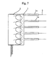
- a first embodiment of the present invention is explained as follows with reference to FIGS. 1A to 7.
- FIGS. 1A to 1F are views for explaining steps for manufacturing a multi-layer optical fiber sheet according to an embodiment of the present invention.
- FIG. 2 is a structurally enlarged cross section of FIG. 1F structurally viewed in a line A-A so as to show a relationship of each layer in a manufactured multi-layer optical fiber sheet.
- the multi-layer optical fiber sheet shown in the drawing quite a long extra length of optical fiber which is formed on the optical fiber wiring section is contained in the optical fiber sheet.
- a material member for a sheet which is used for outermost layers which are on top and the bottom of the sheet is a flexible resin sheet.
- the material member and the thickness are selected preferably in consideration of Young's modulus according to necessary factors such as handling operability, anti-abrasion, rigidity (anti-bending rigidity), and tensile strength.
- a film such as polyimide, polyethyleneterefthalate, low density or high density polyethylene, polyprophlene, polyester, nylon 6, nylon 66, ethylene-tetrafluoroethylene copolymer, poly 4-methylpentene, polyvinyllidene chloride, plasticized polyvinylchloride, polyetherester copolymer, ethylene-vinylacetate copolymer, soft polyurethane.
- any of the sheet material For example, it is possible to use the same material member as in the top layer and the bottom layer. Also, it is possible to use different material member in the top layer from the bottom layer. It may be acceptable if the thickness of the sheet may be the same as in top and bottom sheet. Also, it may be acceptable if the thickness of the sheet may be different between the top sheet and the bottom sheet. Also, a room temperature pressure sensitive bonding agent (adhesive agent) including a rubber or acryl is applied on a surface of the sheet member so as to attach together.
- an optical fiber which is disposed on the sheet is not limited particularly, so called a UV (ultraviolet) line (diameter 250 ⁇ m) which is formed by a UV resin coating on a bare fiber, or a silicon wire on which a silicon resin is coated is usually used. Also, it is possible to use an optical fiber cord of which optical fiber core and a protecting coat are reinforced, an optical fiber tape cord of which optical fiber tape core and a protecting coat are reinforced, and a carbon coat fiber according to necessity. Also, in the embodiments of the present invention, explanation is not limited to a case in which a first sheet is the bottom layer and a second sheet is the top layer. More importantly, an opposite structure is acceptable. If there are more than three sheets, it is acceptable if a sheet which is not disposed on the outermost layer may be the first sheet.
- an optical fiber 5 is disposed on a first sheet 1 (bottom layer) as shown in FIG. 1A.
- a pressure sensitive bonding agent is applied on an upper surface of the sheet 1, and an optical fiber 5 is disposed thereon at a desirable pattern so as to be pushed by a slight pushing force.
- the optical fiber 5 adheres to the sheets thus such a wiring condition is maintained.
- the desirable pattern indicates a wiring condition in which overlapping optical fibers are prevented as much as possible so as to realize a sufficient curvature such that a bending loss of the light may be restricted in an acceptable range.
- the above feature such as thickness of the sheet, a compressing operation for the sheet, and a desirable pattern can be employed preferably in the rest of the embodiments of the present invention.
- FIG. 1A it is understood that a region which is indicated by an arrow "a" is used for inputting purpose. Also, as understood from the drawing, an outputting region for the optical fiber 5 is omitted in the drawing.
- a second sheet 2 in which, for example, a rectangular notched section 2a is formed as an interlayer communicating section is applied in a right-bottom region in the drawing for a viewer on the first wired sheet 1.
- This sheet 2 is an interlayer sheet in which thick pressure sensitive bonding agent (adhesive member) is disposed between dual-surfaced removal papers (separators).
- a removal paper is removed so as to expose an adhesive layer so as to be compressed in a predetermined position of the sheet 1 such that the optical fiber is sandwiched therebetween.
- the other removal paper on the sheet 2 is removed so as to expose the pressure sensitive bonding agent (adhesive member). That is, the sheet 2 is formed only by a pressure sensitive bonding agent layer.
- FIG. 1C an outputting region of the optical fiber 5 which is disposed on the first sheet 1 is introduced on the second sheet 2 via the notched section 2a so as not to expand over the sheet; thus, the optical fiber 5 is disposed on the second sheet 2.
- wiring section in a first wiring layer (a region which is indicated by a broken line in FIG. 1B) is omitted.
- a sheet 3 having a rectangular notched section 3a formed in a upper-left region for the viewer in the drawing is applied on the wired second sheet 2 such that the rectangular notched section 3a should be disposed in different position (in different comer in this embodiment) from a position of the notched section formed on the second sheet 2.
- the sheet 3 is also an intermediate layer which has a similar structure with the second sheet 2.
- an order for applying the sheets is similar to the above case; thus, explanation is omitted.
- FIG. 1E As similar to the previous step, an outputting region of the optical fiber 5 which is disposed on the second sheet 2 is introduced on the third sheet 3 via the notched section 3a so as to be disposed on the third sheet 3.
- wiring section in a second wiring layer (a region which is indicated by a broken line in FIG. 1D) is omitted.
- a top fourth sheet 4 which has the same shape as the bottom sheet 1 is applied on the wired third sheet 3.
- the pressure sensitive bonding agent is applied on a surface of the sheet 4.
- a multi-layer optical fiber sheet 6 is formed in which optical fibers are disposed over three wiring layers (wiring planes).
- an intermediate layer which is formed by a plurality of layers of pressure sensitive bonding agent is formed between the material members for the sheets which are layered vertically, and optical fibers are disposed so as to be embedded on a plurality of different planes (wiring planes) in the intermediate layers.
- such an intermediate layer there is a case in which it is difficult to separate the layers because the layers are unitarily formed by a compressing operation; thus, a border between the adhesive layers is not clear, or there is no border betwee the adhesive layers.
- such an intermediate layer can be a plurality of wiring layers (multi-layer) because there are a plurality of wiring planes in the optical fiber viewed in a cross section of the optical fiber sheet. Therefore, such an intermediate layer can be in a range of the present invention. That is, in the present invention, an intermediate layer for fixing the optical fiber is formed between the optical fiber sheets which are layered vertically, and the optical fiber has different wiring planes in the intermediate layers.
- optical fiber paths which communicates among the wiring planes (layers) are formed inside the optical fiber sheet.
- the intermediate layer is formed by an acrylic pressure sensitive bonding agent (adhesive agent), it is not necessary that the intermediate layer should maintain an adhesive characteristics after it is applied on the sheet. That is, an object of the intermediate layer is to maintain a wiring condition of the disposed optical fibers flexibly therefore, a material for the intermediate layer is not limited to a material member which has a common adhesive agent. It is in a range of the present invention if a material member which has an aging characteristic so as to become a rubber elastomer after being attached or a material member which decomposes according to a thermal history is used for the intermediate layer.
- a sheet which is formed by disposing a thick pressure sensitive bonding agent (adhesive agent) between double-surfaced removal papers is used for each intermediate layer.
- a sheet in which a pressure sensitive bonding agent is applied on both sides of the material members for the sheet which is similar to the outermost layer as a part of the intermediate sheet as an object for enhancing a rigidity of the sheet.
- the intermediate layer may be a composite in which several sheets having only an adhesive agent and sheets having a material member are combined.
- the optical fiber 5 is disposed over three wiring layers (wiring planes). Therefore, although a sheet area is limited, the optical fibers 5 which are disposed in each wiring layer are not so dense (crowded). Therefore, the optical fibers do not cross each other in each wiring layer. Otherwise, only a few optical fibers cross each other even if there is such optical fibers which are crossing each other.
- the neighboring sheets which are layered vertically are contacting each other closely; thus, the optical fibers are fixed reliably; thus, there is not a concern that the optical fibers move in the sheet. Therefore, there is not a concern that the optical fibers may be disposed inaccurately on the sheet such that the optical fibers may be damaged when the optical fiber sheet is assembled in a device.
- each optical fiber is drawn from a region near the sheet in the present embodiment, positions from which each optical fiber is drawn thereout is different when viewed from a cross sectional direction of the sheet. Therefore, there is not a multiple crossing between the optical fibers. Otherwise, even if there is a multiple crossing between the optical fibers, it is possible to design a wiring shape in which there may be less number of multiple crossings.
- FIGS. 3A to 3F are showing manufacturing steps for a multi-layer optical fiber sheet 6A in which two single core optical fibers (or a single two-core optical fiber tape) are disposed.
- FIGS. 3A to 3D correspond to FIGS. 1A to 1D except that two optical fibers are used (two optical fibers are indicated by reference numerals 5 and 5').
- FIG. 3E an optical fiber is introduced onto a third sheet 3 via a notched section 3a so as to be disposed on the third sheet 3 as similar to FIGS. 1A to 1F.
- the other optical fiber 5' is not disposed on the sheet 3. Instead, the optical fiber 5' is drawn out of the sheet. Consequently, a fourth sheet 4 is applied thereon.
- a multi-layer optical fiber sheet 6A in which two optical fibers 5 and 5' are disposed over three layers is manufactured.
- n-core optical fiber tape (n is an integer)
- the above wiring disposition is performed by cutting the n-core optical fiber tape into a single core optica fiber at a preferable position on the sheet; thus, the optical fiber which is cut is drawn out of the sheet similar to the above explanation.
- the other optical fiber 5' is drawn out of the sheet from the notched section 3a as shown in FIGS. 3D and 3E, it is possible to select the region for drawing out the optical fiber preferably.
- the optical fiber 5' may be drawn out of the sheet horizontally from, for example, a left member of the sheet.
- optical fibers or a four-core optical fiber
- FIG. 6 corresponds to a step shown in FIG. 1D among manufacturing steps shown in FIGS. 1A to 1F.
- an outputting section of the optical fiber 5 which is disposed on the second sheet 2 is introduced onto the third sheet 3 via the hole 3b so as to be disposed on the third sheet 3.
- either one of the neighboring sheets is smaller than the other sheet, that is, if a longitudinal width and a latitudinal width are narrower, it is possible to form a non-conforming section.
- a third embodiment of the present invention is explained with reference to FIGS. 8A to 8F, 9, 10, 4, and 5.
- a portion of the optical fiber which is drawn out of the sheet is covered by a reinforcing tube which is provided with a reinforcing texture layer.
- a reinforcing tube which is provided with a reinforcing texture layer.
- an optical connector optical ferrule
- a common single-core SC optical ferrule can be used.
- a multi-core MT optical ferrule can be used preferably.
- FIGS. 8A to 8F are views for explaining a method for manufacturing an optical fiber sheet of the present invention.
- FIG. 9 is an enlarged cross section of manufactured optical fiber sheet FIG. 8C viewed in a line A-A.
- an optical fiber 12 is disposed on a flexible resin sheet (a first sheet) 11 on which a pressure sensitive bonding agent is applied.
- a flexible resin sheet a first sheet
- an optical connector 14 is attached to an outputting section.
- a material member for a sheet which is used for outermost layers which are on top and the bottom of the sheet is a flexible resin sheet.
- the material member and the thickness are selected preferably in consideration of Young's modulus according to necessary factors such as handling operability, anti-abrasion, rigidity (anti-bending rigidity), and tensile strength.
- a film such as polyimide, polyethyleneterefthalate, low density or high density polyethylene, polyprophlene, polyester, nylon 6, nylon 66, ethylene-tetrafluoroethylene copolymer, poly 4-methylpentene, polyvinyllidene chloride, plasticized polyvinylchloride, polyetherester copolymer, ethylene-vinylacetate copolymer, soft polyurethane.
- any of the sheet material For example, it is possible to use the same material member as in the top layer and the bottom layer. Also, it is possible to use different material member in the top layer from the bottom layer.
- a room temperature pressure sensitive bonding agent including a rubber or acryl is applied on a surface of the sheet member so as to attach together.
- an optical fiber which is disposed on the sheet is not limited particularly, so called a UV (ultraviolet) line (diameter 250 ⁇ m) which is formed by a UV resin coating on a bare fiber, or a silicon wire on which a silicon resin is coated is usually used.
- an optical fiber cord of which optical fiber core and a protecting coat are reinforced an optical fiber tape cord of which optical fiber tape core and a protecting coat are reinforced, and a carbon coat fiber according to necessity.
- a second sheet 15 which is supposed to be an intermediate layer having, for example, a rectanbular notched section 15a for an interlayer communicating section is attached in a right-top region of the sheet 11 for a viewer on the first wired sheet 11.
- the sheet 15 is formed by disposing a thick pressure sensitive bonding agent (adhesive agent) layer between a double-surfaced removal papers such that an adhesive layer is exposed by removing a removal paper so as to be compressed to be attached in a predetermined position on the sheet 11 so as to dispose the wired optical fiber 12 therebetween.
- the other removal paper is removed so as to expose the pressure sensitive bonding agent (adhesive agent). That is, the sheet 15 is formed only by a layer of the pressure sensitive bonding agent.
- the optical fiber 12 is bent downwardly in the drawing in the notched section 15a so as to dispose an extra length portion of the optical fiber 12 tentatively on the attached sheet 15.
- the extra length part which is tentatively disposed to roll around on the sheet 15 is indicated by reference numeral 12'.
- the drawn part of the optical fiber is cut such that a predetermined length L 1 is drawn from a marginal end of the sheet.
- the drawn length Li corresponds to a final position in which the optical connector 14 is attached as shown in FIG. 8E.
- the extra length section (also indicated by reference numeral 12a) is disposed on a surface of the sheet 15. If such an extra length section for the optical connector 14 is disposed successfully for the first time, the extra length section is disposed in the same pattern as the tentative disposition pattern shown in FIG. 8C. By doing this, it is possible to attach the optical connector 14 according to a designed distance L 3 (or L 1 ) from the marginal end of the sheet correctly. Therefore, it is possible to manufacture an optical fiber sheet having a short extra length section (a distance L 3 from the marginal end of the sheet to the rear end of the optical connector is short) easily. Also, it is possible to manufacture an optical fiber sheet having no extra length section (a distance L 3 is zero) easily.
- the optical connector 14 cannot be attached successfully in a manufacturing step shown in FIG. 8D because a sufficient optical performance cannot be realized or the optical fiber is broken, it is possible to cut the tip of the optical fiber 2 so as to attach the optical connector 4 again because there is a sufficient extra length to be attached.
- the extra length section 12a is disposed on a surface of the sheet 15, the extra length section 12 is slightly different from the tentative disposition pattern shown in FIG. 8C because the extra length section 12a is slightly short.
- the disposing operation should be performed in consideration of the above difference, it should be noted that there may be a case in which there may not be a region for rolling the optical fiber in the sheet.
- a sheet 16 (third sheet) on which surface a pressure sensitive bonding agent is applied having an area for covering the notched section 15a is attached on the sheet 15 in which an extra length section is formed.
- a two-layer structure optical fiber sheet 17 is manufactured in which an optical fiber for the outputting use is disposed on a layer (wiring plane) which is different from the optical fiber for the inputting use and the sheet 15.
- Embodiments shown in FIGS. 10 and 4 relates to a optical fiber sheet in which, for example, four optical fibers 12 are disposed.
- an inputting section is an optical fiber tape in which four pieces of single-core optical fibers 12 are bundled.
- the optical fiber tape is attached to a four-core optical fiber connector 13A so as to be disposed on the optical fiber sheet 1.
- the disposed optical fiber tape is cut into a single-core optical fiber 12a in the sheet so as to be drawn out of the sheet.
- An optical connector for a single-core optical fiber is attached on a tip of the single-core optical fiber 12a.
- any desirable number of optical fibers can be disposed.
- the inputting section is a four-core optical fiber tape so as to be cut into optical fibers having less number of cores such as a single-core optical fiber tape or a two-core optical fiber tape.
- the optical fiber has a dimensional two-layer structure; therefore, even if the extra length section (upper wiring layer) is disposed so as to overlap the necessary wiring section (lower wiring layer), the optical fibers are not disposed crowdedly. Thus, it is possible to avoid the multiple crossing of the optical fibers easily. Therefore, it is not necessary to form an extra area for containing such an extra length section by enlarging the sheet area.
- FIG. 10 corresponds to a manufacturing step shown in FIG. 8E in which an optical fiber sheet 17A is manufactured by attaching a third sheet 16 on the sheet 15 in which an extra length section 12a of the optical fiber is disposed as shown in FIG. 4.
- the notched section 15a which is supposed to be formed on the sheet 15 for disposing an extra length section is disposed in a marginal end section in an outputting section of the optical fiber sheet.
- the notched section 15a' in an inputting section shown in FIG. 5 which shows a corresponding manufacturing step s to that of FIG. 8F. That is, it is possible to form a notched section in the marginal end section in either one of the sheet of the optical fiber which is disposed on the optical fiber sheet.
- the present invention can be applied to a case in which more than three-layer structure is employed.
- four optical fibers Quantity of core can be determined preferably whether to use four pieces of single-core optical fibers or a four-core optical fiber
- four optical fibers 12 which are disposed on the first sheet 11 are drawn out from the notched section 15a formed on the second sheet 15 which is supposed to be an intermediate layer so as to form an interlayer communicating section; thus, the optical fibers are disposed on the second sheet 15.
- optical connector is attached so as to dispose the optical fiber again (see FIG. 11A).
- the rest of two optical fibers 12 are drawn out from the notched section 16'a which is formed on the third sheet 16' which is supposed to be an intermediate layer so as to be attached on the second sheet 15 so as to be disposed on the third sheet 16'.
- the optical connector is attached according to the above method so as to dispose the optical fiber again.
- a fourth sheet 20 is attached thereon (see FIG. 11B).
- the extra length for attaching the optical connector 14 to the two optical fibers 12 on the second sheet 15 may be the same the extra length for attaching the optical connector 14 to the optical fibers 12 on the third sheet 16'.
- the extra length for attaching the optical connector 14 to the two optical fibers 12 on the second sheet 15 may be different from the extra length for attaching the optical connector 14 to the optical fibers 12 on the third sheet 16'.
- the present invention includes such a case because wiring planes for the optical fibers are different. It is difficult to separate such interlayers which are usually unitarily compressed. Otherwise, the border between the adhesive layers are unclear. Furthermore, there may be a case in which there is no border between the adhesive layers. In such a case, there are a plurality of wiring planes for the optical fibers when viewed from a cross section of the optical fiber sheet; it is possible to understand that such a structure may be a plurality of wiring layers (multi-layers). Therefore, such a structure can be included in a technical scope of the present invention.
- an intermediate layer for fixing an optical fiber between optical fiber sheets which are layered vertically is disposed, and the optical fiber has different wiring planes in the intermediate layer. Consequently, the optical fiber paths which communicate among the wiring planes (layers) are formed inside the optical fiber sheet.
- the intermediate layer is an acrylic pressure sensitive bonding agent (adhesive agent) layer, it is not necessary to maintain such adhesion after the sheet is attached. That is, object of the intermediate layer is to maintain a wiring condition of the disposed optical fibers flexibly; therefore, a material for the intermediate layer is not limited to a material member which has a common adhesive agent. It is in a range of the present invention if a material member which has an aging characteristic so as to become a rubber elastomer after being attached or a material member which decomposes according to a thermal history is used for the intermediate layer.
- an intermediate sheet which is formed by disposing a thick pressure sensitive bonding agent (adhesive agent) between double-surfaced removal papers is used for each intermediate layer.
- a sheet in which a pressure sensitive bonding agent is applied on both sides of the material members for the sheet which is similar to the outermost layer as a part of the intermediate sheet as an object for enhancing a rigidity of the sheet.
- the intermediate layer may be a composite in which several sheets having only an adhesive agent and sheets having a material member are combined.
- an interlayer communicating section such as a notched section or a hole is formed on the sheet; thus, the optical fiber communicates to a region between the wiring planes via the interlayer communicating section. Therefore, there are less dense optical fibers in each wiring planes; thus, the sheets which are neighboring vertically contact sufficiently closely; thus, the optical fibers are fixed reliably. Therefore, it is possible to reduce a necessary sheet area. Thus, there is no concern in that the optical fiber is disposed in an undesirable position when assembled in the device and there occurs a microbent which damages the optical fiber.
- optical fibers are disposed so as to form at least a two-layer structure in an optical fiber sheet in which optical fibers are drawn out from an interlayer communicating section which is formed in the intermediate sheet in a three-layered sheets apart from the sheets. Therefore, by disposing the optical fibers tentatively or disposing the optical fibers again, it is possible to obtain a sufficient extra length section or more extra length section for re-disposition in the optical fibers which are supposed to be disposed, for example, when optical fibers are attached to the optical fiber which expands from the sheet near the marginal end of the sheet. Therefore, it is possible to attach the optical connectors to the optical fibers which expand from the sheet near the marginal end of the sheet easily. Also, it is possible to attach optical connectors having a short extra length section of the optical fiber which expands from the marginal end of the sheet. Also, it is possible to attach optical connectors having no extra length section of the optical fiber.
- the disposed optical fibers have at least a two-layer wiring planes when the optical connectors are attached to a plurality of the optical fibers near the marginal end of the sheet. Therefore, it is possible to avoid a multiple crossing of the optical fibers easily in which the optical fibers are not crowded even if the extra length section is disposed so as to overlap the necessary wiring section. Therefore, it is not necessary to form a surplus area for the are for containing the extra length section.
- the optical connectors cannot be attached to the either one of the optical fibers successfully, and it is necessary to cut the failed connection and attach new optical connectors again for attaching the optical connectors to a plurality of optical fibers, it is possible to adjust the length of the expanded optical fibers in a predetermined length by adjusting the extra length section (curvature) of the optical fiber on the sheet.
Landscapes
- Physics & Mathematics (AREA)
- General Physics & Mathematics (AREA)
- Optics & Photonics (AREA)
- Light Guides In General And Applications Therefor (AREA)
Abstract
Description
Claims (12)
- A multi-layer optical fiber sheet having multi-layered optical fiber over a plurality of wiring layers which is formed by attaching more than three sheets wherein:an interlayer communicating section is formed in at least an intermediate sheet among the sheets; andthe optical fibers which are disposed in the sheets communicates a region between the wiring layers via the interlayer communicating section.
- A multi-layer optical fiber sheet according to Claim 1 wherein the interlayer communicating section in the sheets which overlap vertically each other do not overlap precisely each other.
- A multi-layer optical fiber sheet according to Claim 1 wherein a plurality of the optical fibers are disposed such that each optical fiber is drawn out of the sheets from different region in the sheets.
- A multi-layer optical fiber sheet according to Claims 1 to 3 wherein the intermediate sheet is mainly made of a pressure sensitive bonding agent.
- A multi-layer optical fiber sheet wherein:an intermediate layer for fixing optical fibers is disposed between optical fiber sheets which are layered vertically;the optical fibers are disposed on different wiring planes in the intermediate layer; andoptical fiber paths for communicating the different wiring planes are formed in a region between the optical fiber sheets which are layered vertically.
- A multi-layer optical fiber sheet according to Claim 5 wherein the intermediate layer is a pressure sensitive bonding agent layer.
- A method for manufacturing an optical fiber sheet comprising the steps for:disposing optical fibers on a first sheet by a desirable pattern;applying a second sheet on the first sheet so as to have an interlayer communicating section therebetween;attaching an optical connector on a tip of an optical fiber which is drawn out of the sheets;disposing the optical fiber to which the optical connector is attached on the second sheet via the interlayer communicating section; andapplying a third sheet on the second sheet.
- A method for manufacturing an optical fiber sheet according to Claim 7 further comprising the steps for:disposing an optical fiber tentatively on the second sheet such that a predetermined length of the optical fiber should be drawn out of an end margin of the sheet;removing the optical fiber which is tentatively disposed on the second sheet;attaching an optical connector on a tip of the removed optical fiber;disposing the optical fiber on the second sheet again; andapplying the third sheet to the second sheet.
- A method for manufacturing an optical fiber sheet according to Claims 7 or 8 wherein the optical fiber is drawn out to the interlayer communicating section.
- A method for manufacturing an optical fiber sheet comprising the steps for:disposing optical fibers on a first sheet by a desirable pattern;applying a second sheet, which is provided with a notched section in a region to which the optical fiber is drawn, on the first sheet;disposing an optical fiber tentatively which expands from the notched section on the second sheet such that a predetermined length of the optical fiber should be drawn out of an end margin of the sheet;removing the optical fiber which is tentatively disposed on the second sheet;disposing the optical fiber on the second sheet again so as to have a predetermined extra length of optical fiber after disposing the optical fiber; andapplying the third sheet to the second sheet.
- An optical fiber sheet wherein:an intermadiate layer for fixing an optical fiber is formed between sheets which are layered vertically;the optical fiber has different wiring plane in the intermediate layer;optical fiber paths which communicates the wiring planes a formed inside the sheets; andthe optical fiber is disposed on the different wiring plane so as be drawn out of the sheets to be connected to the connector.
- An optical fiber sheet according to Claim 1 wherein the intermediate layer is a pressure sensitive bonding agent layer.
Applications Claiming Priority (7)
| Application Number | Priority Date | Filing Date | Title |
|---|---|---|---|
| JP2001107689 | 2001-04-05 | ||
| JP2001107689 | 2001-04-05 | ||
| JP2002019116A JP4030041B2 (en) | 2001-04-05 | 2002-01-28 | Multilayer optical fiber sheet |
| JP2002019117A JP4030042B2 (en) | 2001-04-05 | 2002-01-28 | Manufacturing method of optical fiber sheet |
| JP2002019117 | 2002-01-28 | ||
| JP2002019116 | 2002-01-28 | ||
| PCT/JP2002/003448 WO2002082132A1 (en) | 2001-04-05 | 2002-04-05 | Multilayer optical fiber sheet, optical fiber sheet fabricating method, and optical fiber sheet |
Publications (3)
| Publication Number | Publication Date |
|---|---|
| EP1376165A1 true EP1376165A1 (en) | 2004-01-02 |
| EP1376165A4 EP1376165A4 (en) | 2006-09-06 |
| EP1376165B1 EP1376165B1 (en) | 2011-12-21 |
Family
ID=27346471
Family Applications (1)
| Application Number | Title | Priority Date | Filing Date |
|---|---|---|---|
| EP02714504A Expired - Lifetime EP1376165B1 (en) | 2001-04-05 | 2002-04-05 | Multilayer optical fiber sheet, optical fiber sheet fabricating method, and optical fiber sheet |
Country Status (4)
| Country | Link |
|---|---|
| US (1) | US7352921B2 (en) |
| EP (1) | EP1376165B1 (en) |
| AT (1) | ATE538399T1 (en) |
| WO (1) | WO2002082132A1 (en) |
Cited By (4)
| Publication number | Priority date | Publication date | Assignee | Title |
|---|---|---|---|---|
| EP1361464A3 (en) * | 2002-05-02 | 2004-12-29 | Tomoegawa Paper Co. Ltd. | Optical interconnection apparatus |
| CN100430763C (en) * | 2004-10-27 | 2008-11-05 | 株式会社巴川制纸所 | Optical fiber structure and method of making the same |
| US7509009B2 (en) | 2005-03-23 | 2009-03-24 | Tomoegawa Paper Co., Ltd | Optical fiber structure and method of manufacturing same |
| CN109952521A (en) * | 2016-11-07 | 2019-06-28 | 康普技术有限责任公司 | Flexible optical fiber circuit and manufacturing method thereof |
Families Citing this family (18)
| Publication number | Priority date | Publication date | Assignee | Title |
|---|---|---|---|---|
| JP3866172B2 (en) * | 2002-08-27 | 2007-01-10 | 富士通株式会社 | Optical module and fiber sheet |
| JP4334211B2 (en) * | 2002-12-25 | 2009-09-30 | スリーエム イノベイティブ プロパティズ カンパニー | Optical wiring sheet |
| US20040161212A1 (en) * | 2003-02-18 | 2004-08-19 | Sun Maurice X. | Fiber optic apparatus |
| US7359641B2 (en) * | 2003-07-28 | 2008-04-15 | Emcore Corporation | Modular optical transceiver |
| US6974260B2 (en) * | 2003-07-30 | 2005-12-13 | Emcore Corporation | Flexible substrate for routing fibers in an optical transceiver |
| US7139456B2 (en) * | 2004-10-27 | 2006-11-21 | Tomoegawa Paper Co., Ltd. | Optical fiber wiring sheet and method of manufacturing same |
| US9229172B2 (en) | 2011-09-12 | 2016-01-05 | Commscope Technologies Llc | Bend-limited flexible optical interconnect device for signal distribution |
| US9417418B2 (en) | 2011-09-12 | 2016-08-16 | Commscope Technologies Llc | Flexible lensed optical interconnect device for signal distribution |
| US8842961B2 (en) * | 2012-06-11 | 2014-09-23 | Tyco Electronics Corporation | Universal fan-out device |
| US9488788B2 (en) | 2012-09-28 | 2016-11-08 | Commscope Technologies Llc | Fiber optic cassette |
| US9223094B2 (en) | 2012-10-05 | 2015-12-29 | Tyco Electronics Nederland Bv | Flexible optical circuit, cassettes, and methods |
| WO2015161204A1 (en) * | 2014-04-17 | 2015-10-22 | Molex Incorporated | Multi-layer flexible optical circuit |
| US9494763B2 (en) * | 2015-02-04 | 2016-11-15 | International Business Machines Corporation | Optical fiber routing mat |
| CN108603990B (en) * | 2016-01-12 | 2021-05-28 | 康普连通比利时私人有限公司 | Cable management arrangement |
| WO2018046677A1 (en) | 2016-09-08 | 2018-03-15 | CommScope Connectivity Belgium BVBA | Telecommunications distribution elements |
| MX2020002878A (en) | 2017-10-02 | 2020-07-22 | Commscope Technologies Llc | Fiber optic circuit and preparation method. |
| WO2019195602A1 (en) | 2018-04-06 | 2019-10-10 | Commscope Technologies Llc | Flexible organizer and self-supporting unit |
| US12339511B2 (en) | 2020-03-31 | 2025-06-24 | Commscope Technologies Llc | Fiber optic cable management systems and methods |
Family Cites Families (11)
| Publication number | Priority date | Publication date | Assignee | Title |
|---|---|---|---|---|
| GB8720103D0 (en) * | 1987-08-26 | 1987-09-30 | British Telecomm | Corner guide |
| US5204925A (en) * | 1991-09-11 | 1993-04-20 | At&T Bell Laboratories | Optical interconnection of circuit packs |
| JPH07128563A (en) | 1993-11-02 | 1995-05-19 | Mitsubishi Cable Ind Ltd | Connecting surplus length housing device |
| JPH0886920A (en) | 1994-09-20 | 1996-04-02 | Mitsubishi Cable Ind Ltd | Holding structure for optical fiber |
| JP3340582B2 (en) * | 1995-03-07 | 2002-11-05 | 株式会社正電社 | Laminated optical fiber cable storage case |
| JP3130265B2 (en) | 1997-01-21 | 2001-01-31 | 東日本電信電話株式会社 | Core connection module |
| JP3313060B2 (en) * | 1998-01-19 | 2002-08-12 | 株式会社巴川製紙所 | Optical connection component and method of manufacturing the same |
| US6185348B1 (en) * | 1999-01-19 | 2001-02-06 | Lucent Technologies Inc. | Apparatus and method for manufacturing a multifiber interconnection circuit |
| JP3326403B2 (en) * | 1999-03-30 | 2002-09-24 | 株式会社巴川製紙所 | Optical connection parts |
| US6324325B1 (en) * | 2000-02-04 | 2001-11-27 | Bruce L. Booth | Thereof fiber interconnection apparatus and process for the preparation |
| US6516114B2 (en) * | 2000-06-27 | 2003-02-04 | Oluma, Inc. | Integration of fibers on substrates fabricated with grooves |
-
2002
- 2002-04-05 US US10/473,885 patent/US7352921B2/en not_active Expired - Fee Related
- 2002-04-05 WO PCT/JP2002/003448 patent/WO2002082132A1/en not_active Ceased
- 2002-04-05 AT AT02714504T patent/ATE538399T1/en active
- 2002-04-05 EP EP02714504A patent/EP1376165B1/en not_active Expired - Lifetime
Cited By (5)
| Publication number | Priority date | Publication date | Assignee | Title |
|---|---|---|---|---|
| EP1361464A3 (en) * | 2002-05-02 | 2004-12-29 | Tomoegawa Paper Co. Ltd. | Optical interconnection apparatus |
| CN100430763C (en) * | 2004-10-27 | 2008-11-05 | 株式会社巴川制纸所 | Optical fiber structure and method of making the same |
| US7509009B2 (en) | 2005-03-23 | 2009-03-24 | Tomoegawa Paper Co., Ltd | Optical fiber structure and method of manufacturing same |
| CN109952521A (en) * | 2016-11-07 | 2019-06-28 | 康普技术有限责任公司 | Flexible optical fiber circuit and manufacturing method thereof |
| CN109952521B (en) * | 2016-11-07 | 2021-09-17 | 康普技术有限责任公司 | Flexible optical fiber circuit and manufacturing method thereof |
Also Published As
| Publication number | Publication date |
|---|---|
| EP1376165B1 (en) | 2011-12-21 |
| WO2002082132A1 (en) | 2002-10-17 |
| ATE538399T1 (en) | 2012-01-15 |
| EP1376165A4 (en) | 2006-09-06 |
| US7352921B2 (en) | 2008-04-01 |
| US20040213505A1 (en) | 2004-10-28 |
Similar Documents
| Publication | Publication Date | Title |
|---|---|---|
| US7352921B2 (en) | Multilayer optical fiber sheet, optical fiber sheet fabricating method, and optical fiber sheet | |
| EP0829028B1 (en) | Fiber optic ribbon cable and method for its manufacture | |
| EP3649497B1 (en) | High fiber density ribbon cable | |
| JP7307859B2 (en) | fiber optic cable | |
| JP5564026B2 (en) | Optical fiber tape core and optical fiber cable storing the optical fiber core | |
| US5574817A (en) | Fiber optic ribbon cable assembly and method of manufacturing same | |
| US7130498B2 (en) | Multi-layer optical circuit and method for making | |
| JP4980841B2 (en) | Optical fiber ribbon and its dividing method | |
| USH2144H1 (en) | Layered optical circuit | |
| CN110058364A (en) | Fibre ribbon | |
| KR20220011284A (en) | Optical Fiber Ribbon | |
| US20050129347A1 (en) | Optical fiber sheet and optical fiber sheet production method | |
| JP3773584B2 (en) | Fiber optic tape cable | |
| CN120276105B (en) | A multi-unit butterfly-shaped optical cable with composite components | |
| JP2004126310A (en) | Film-shaped member, method of manufacturing the same, partially tape-shaped optical fiber, method of partially tape-shaping optical fiber, multi-core optical connector, optical fiber sheet, and fan-out cord | |
| JP4030042B2 (en) | Manufacturing method of optical fiber sheet | |
| EP1498260A1 (en) | Protective member for protecting electric wires | |
| JP4334211B2 (en) | Optical wiring sheet | |
| JP4030041B2 (en) | Multilayer optical fiber sheet | |
| JP4000474B2 (en) | Optical fiber tape core, optical fiber tape core manufacturing apparatus, and optical fiber tape core manufacturing method | |
| JP2002341208A (en) | Optical fiber ribbon and optical fiber cable | |
| JPH0792359A (en) | Optical fiber device and optical cable and manufacturing apparatus of optical fiber device | |
| JP3472535B2 (en) | Optical connection parts and optical fiber wiring method | |
| JP2005292261A (en) | Optical fiber ribbon | |
| JP2005099642A (en) | Optical fiber sheet manufacturing method |
Legal Events
| Date | Code | Title | Description |
|---|---|---|---|
| PUAI | Public reference made under article 153(3) epc to a published international application that has entered the european phase |
Free format text: ORIGINAL CODE: 0009012 |
|
| 17P | Request for examination filed |
Effective date: 20031003 |
|
| AK | Designated contracting states |
Kind code of ref document: A1 Designated state(s): AT BE CH CY DE DK ES FI FR GB GR IE IT LI LU MC NL PT SE TR |
|
| AX | Request for extension of the european patent |
Extension state: AL LT LV MK RO SI |
|
| A4 | Supplementary search report drawn up and despatched |
Effective date: 20060807 |
|
| 17Q | First examination report despatched |
Effective date: 20091116 |
|
| GRAP | Despatch of communication of intention to grant a patent |
Free format text: ORIGINAL CODE: EPIDOSNIGR1 |
|
| GRAS | Grant fee paid |
Free format text: ORIGINAL CODE: EPIDOSNIGR3 |
|
| GRAA | (expected) grant |
Free format text: ORIGINAL CODE: 0009210 |
|
| RIN1 | Information on inventor provided before grant (corrected) |
Inventor name: SAITO, DAIGO,C/O FUJIKURA LTD., SAKURA WORKS Inventor name: HAYASHI, YUKIO,C/O FUJIKURA LTD., SAKURA WORKS Inventor name: SHIMOMICHI, TSUYOSHI,C/O FUJIKURA LTD., SAKURA WOR Inventor name: TAKIZAWA, KAZUHIRO,C/O FUJIKURA LTD., SAKURA WORKS Inventor name: TAMAKI, YASUHIRO,C/O FUJIKURA LTD., SAKURA WORKS |
|
| AK | Designated contracting states |
Kind code of ref document: B1 Designated state(s): AT BE CH CY DE DK ES FI FR GB GR IE IT LI LU MC NL PT SE TR |
|
| REG | Reference to a national code |
Ref country code: GB Ref legal event code: FG4D |
|
| REG | Reference to a national code |
Ref country code: CH Ref legal event code: EP |
|
| REG | Reference to a national code |
Ref country code: AT Ref legal event code: REF Ref document number: 538399 Country of ref document: AT Kind code of ref document: T Effective date: 20120115 |
|
| REG | Reference to a national code |
Ref country code: IE Ref legal event code: FG4D |
|
| REG | Reference to a national code |
Ref country code: DE Ref legal event code: R096 Ref document number: 60241790 Country of ref document: DE Effective date: 20120216 |
|
| REG | Reference to a national code |
Ref country code: NL Ref legal event code: VDEP Effective date: 20111221 |
|
| PG25 | Lapsed in a contracting state [announced via postgrant information from national office to epo] |
Ref country code: NL Free format text: LAPSE BECAUSE OF FAILURE TO SUBMIT A TRANSLATION OF THE DESCRIPTION OR TO PAY THE FEE WITHIN THE PRESCRIBED TIME-LIMIT Effective date: 20111221 Ref country code: GR Free format text: LAPSE BECAUSE OF FAILURE TO SUBMIT A TRANSLATION OF THE DESCRIPTION OR TO PAY THE FEE WITHIN THE PRESCRIBED TIME-LIMIT Effective date: 20120322 Ref country code: SE Free format text: LAPSE BECAUSE OF FAILURE TO SUBMIT A TRANSLATION OF THE DESCRIPTION OR TO PAY THE FEE WITHIN THE PRESCRIBED TIME-LIMIT Effective date: 20111221 |
|
| PG25 | Lapsed in a contracting state [announced via postgrant information from national office to epo] |
Ref country code: CY Free format text: LAPSE BECAUSE OF FAILURE TO SUBMIT A TRANSLATION OF THE DESCRIPTION OR TO PAY THE FEE WITHIN THE PRESCRIBED TIME-LIMIT Effective date: 20111221 Ref country code: BE Free format text: LAPSE BECAUSE OF FAILURE TO SUBMIT A TRANSLATION OF THE DESCRIPTION OR TO PAY THE FEE WITHIN THE PRESCRIBED TIME-LIMIT Effective date: 20111221 |
|
| PG25 | Lapsed in a contracting state [announced via postgrant information from national office to epo] |
Ref country code: PT Free format text: LAPSE BECAUSE OF FAILURE TO SUBMIT A TRANSLATION OF THE DESCRIPTION OR TO PAY THE FEE WITHIN THE PRESCRIBED TIME-LIMIT Effective date: 20120423 |
|
| PGFP | Annual fee paid to national office [announced via postgrant information from national office to epo] |
Ref country code: GB Payment date: 20120423 Year of fee payment: 11 |
|
| REG | Reference to a national code |
Ref country code: AT Ref legal event code: MK05 Ref document number: 538399 Country of ref document: AT Kind code of ref document: T Effective date: 20111221 |
|
| PLBE | No opposition filed within time limit |
Free format text: ORIGINAL CODE: 0009261 |
|
| STAA | Information on the status of an ep patent application or granted ep patent |
Free format text: STATUS: NO OPPOSITION FILED WITHIN TIME LIMIT |
|
| PG25 | Lapsed in a contracting state [announced via postgrant information from national office to epo] |
Ref country code: DK Free format text: LAPSE BECAUSE OF FAILURE TO SUBMIT A TRANSLATION OF THE DESCRIPTION OR TO PAY THE FEE WITHIN THE PRESCRIBED TIME-LIMIT Effective date: 20111221 |
|
| 26N | No opposition filed |
Effective date: 20120924 |
|
| PG25 | Lapsed in a contracting state [announced via postgrant information from national office to epo] |
Ref country code: MC Free format text: LAPSE BECAUSE OF NON-PAYMENT OF DUE FEES Effective date: 20120430 Ref country code: IT Free format text: LAPSE BECAUSE OF FAILURE TO SUBMIT A TRANSLATION OF THE DESCRIPTION OR TO PAY THE FEE WITHIN THE PRESCRIBED TIME-LIMIT Effective date: 20111221 |
|
| REG | Reference to a national code |
Ref country code: CH Ref legal event code: PL |
|
| REG | Reference to a national code |
Ref country code: IE Ref legal event code: MM4A |
|
| REG | Reference to a national code |
Ref country code: DE Ref legal event code: R097 Ref document number: 60241790 Country of ref document: DE Effective date: 20120924 |
|
| PG25 | Lapsed in a contracting state [announced via postgrant information from national office to epo] |
Ref country code: CH Free format text: LAPSE BECAUSE OF NON-PAYMENT OF DUE FEES Effective date: 20120430 Ref country code: IE Free format text: LAPSE BECAUSE OF NON-PAYMENT OF DUE FEES Effective date: 20120405 Ref country code: LI Free format text: LAPSE BECAUSE OF NON-PAYMENT OF DUE FEES Effective date: 20120430 Ref country code: AT Free format text: LAPSE BECAUSE OF FAILURE TO SUBMIT A TRANSLATION OF THE DESCRIPTION OR TO PAY THE FEE WITHIN THE PRESCRIBED TIME-LIMIT Effective date: 20111221 |
|
| PG25 | Lapsed in a contracting state [announced via postgrant information from national office to epo] |
Ref country code: FI Free format text: LAPSE BECAUSE OF FAILURE TO SUBMIT A TRANSLATION OF THE DESCRIPTION OR TO PAY THE FEE WITHIN THE PRESCRIBED TIME-LIMIT Effective date: 20111221 |
|
| PG25 | Lapsed in a contracting state [announced via postgrant information from national office to epo] |
Ref country code: ES Free format text: LAPSE BECAUSE OF FAILURE TO SUBMIT A TRANSLATION OF THE DESCRIPTION OR TO PAY THE FEE WITHIN THE PRESCRIBED TIME-LIMIT Effective date: 20120401 |
|
| GBPC | Gb: european patent ceased through non-payment of renewal fee |
Effective date: 20130405 |
|
| PG25 | Lapsed in a contracting state [announced via postgrant information from national office to epo] |
Ref country code: GB Free format text: LAPSE BECAUSE OF NON-PAYMENT OF DUE FEES Effective date: 20130405 |
|
| PG25 | Lapsed in a contracting state [announced via postgrant information from national office to epo] |
Ref country code: TR Free format text: LAPSE BECAUSE OF FAILURE TO SUBMIT A TRANSLATION OF THE DESCRIPTION OR TO PAY THE FEE WITHIN THE PRESCRIBED TIME-LIMIT Effective date: 20111221 |
|
| PG25 | Lapsed in a contracting state [announced via postgrant information from national office to epo] |
Ref country code: LU Free format text: LAPSE BECAUSE OF NON-PAYMENT OF DUE FEES Effective date: 20120405 |
|
| PGFP | Annual fee paid to national office [announced via postgrant information from national office to epo] |
Ref country code: FR Payment date: 20140409 Year of fee payment: 13 Ref country code: DE Payment date: 20140430 Year of fee payment: 13 |
|
| REG | Reference to a national code |
Ref country code: DE Ref legal event code: R119 Ref document number: 60241790 Country of ref document: DE |
|
| PG25 | Lapsed in a contracting state [announced via postgrant information from national office to epo] |
Ref country code: DE Free format text: LAPSE BECAUSE OF NON-PAYMENT OF DUE FEES Effective date: 20151103 |
|
| REG | Reference to a national code |
Ref country code: FR Ref legal event code: ST Effective date: 20151231 |
|
| PG25 | Lapsed in a contracting state [announced via postgrant information from national office to epo] |
Ref country code: FR Free format text: LAPSE BECAUSE OF NON-PAYMENT OF DUE FEES Effective date: 20150430 |