EP1375974A2 - Shifting apparatus for a transmission having a plurality of gear ratios - Google Patents
Shifting apparatus for a transmission having a plurality of gear ratios Download PDFInfo
- Publication number
- EP1375974A2 EP1375974A2 EP03007839A EP03007839A EP1375974A2 EP 1375974 A2 EP1375974 A2 EP 1375974A2 EP 03007839 A EP03007839 A EP 03007839A EP 03007839 A EP03007839 A EP 03007839A EP 1375974 A2 EP1375974 A2 EP 1375974A2
- Authority
- EP
- European Patent Office
- Prior art keywords
- shift
- shaft
- axis
- shift fork
- shift lever
- Prior art date
- Legal status (The legal status is an assumption and is not a legal conclusion. Google has not performed a legal analysis and makes no representation as to the accuracy of the status listed.)
- Granted
Links
Images







Classifications
-
- F—MECHANICAL ENGINEERING; LIGHTING; HEATING; WEAPONS; BLASTING
- F16—ENGINEERING ELEMENTS AND UNITS; GENERAL MEASURES FOR PRODUCING AND MAINTAINING EFFECTIVE FUNCTIONING OF MACHINES OR INSTALLATIONS; THERMAL INSULATION IN GENERAL
- F16H—GEARING
- F16H63/00—Control outputs from the control unit to change-speed- or reversing-gearings for conveying rotary motion or to other devices than the final output mechanism
- F16H63/02—Final output mechanisms therefor; Actuating means for the final output mechanisms
- F16H63/08—Multiple final output mechanisms being moved by a single common final actuating mechanism
- F16H63/20—Multiple final output mechanisms being moved by a single common final actuating mechanism with preselection and subsequent movement of each final output mechanism by movement of the final actuating mechanism in two different ways, e.g. guided by a shift gate
-
- F—MECHANICAL ENGINEERING; LIGHTING; HEATING; WEAPONS; BLASTING
- F16—ENGINEERING ELEMENTS AND UNITS; GENERAL MEASURES FOR PRODUCING AND MAINTAINING EFFECTIVE FUNCTIONING OF MACHINES OR INSTALLATIONS; THERMAL INSULATION IN GENERAL
- F16H—GEARING
- F16H61/00—Control functions within control units of change-speed- or reversing-gearings for conveying rotary motion ; Control of exclusively fluid gearing, friction gearing, gearings with endless flexible members or other particular types of gearing
- F16H61/26—Generation or transmission of movements for final actuating mechanisms
- F16H61/36—Generation or transmission of movements for final actuating mechanisms with at least one movement being transmitted by a cable
-
- F—MECHANICAL ENGINEERING; LIGHTING; HEATING; WEAPONS; BLASTING
- F16—ENGINEERING ELEMENTS AND UNITS; GENERAL MEASURES FOR PRODUCING AND MAINTAINING EFFECTIVE FUNCTIONING OF MACHINES OR INSTALLATIONS; THERMAL INSULATION IN GENERAL
- F16H—GEARING
- F16H59/00—Control inputs to control units of change-speed- or reversing-gearings for conveying rotary motion
- F16H59/02—Selector apparatus
- F16H2059/026—Details or special features of the selector casing or lever support
- F16H2059/0273—Cardan or gimbal type joints for supporting the lever
-
- F—MECHANICAL ENGINEERING; LIGHTING; HEATING; WEAPONS; BLASTING
- F16—ENGINEERING ELEMENTS AND UNITS; GENERAL MEASURES FOR PRODUCING AND MAINTAINING EFFECTIVE FUNCTIONING OF MACHINES OR INSTALLATIONS; THERMAL INSULATION IN GENERAL
- F16H—GEARING
- F16H59/00—Control inputs to control units of change-speed- or reversing-gearings for conveying rotary motion
- F16H59/02—Selector apparatus
- F16H59/04—Ratio selector apparatus
- F16H59/042—Ratio selector apparatus comprising a final actuating mechanism
-
- F—MECHANICAL ENGINEERING; LIGHTING; HEATING; WEAPONS; BLASTING
- F16—ENGINEERING ELEMENTS AND UNITS; GENERAL MEASURES FOR PRODUCING AND MAINTAINING EFFECTIVE FUNCTIONING OF MACHINES OR INSTALLATIONS; THERMAL INSULATION IN GENERAL
- F16H—GEARING
- F16H63/00—Control outputs from the control unit to change-speed- or reversing-gearings for conveying rotary motion or to other devices than the final output mechanism
- F16H63/02—Final output mechanisms therefor; Actuating means for the final output mechanisms
- F16H63/30—Constructional features of the final output mechanisms
- F16H63/34—Locking or disabling mechanisms
- F16H63/36—Interlocking devices
-
- F—MECHANICAL ENGINEERING; LIGHTING; HEATING; WEAPONS; BLASTING
- F16—ENGINEERING ELEMENTS AND UNITS; GENERAL MEASURES FOR PRODUCING AND MAINTAINING EFFECTIVE FUNCTIONING OF MACHINES OR INSTALLATIONS; THERMAL INSULATION IN GENERAL
- F16H—GEARING
- F16H63/00—Control outputs from the control unit to change-speed- or reversing-gearings for conveying rotary motion or to other devices than the final output mechanism
- F16H63/02—Final output mechanisms therefor; Actuating means for the final output mechanisms
- F16H63/30—Constructional features of the final output mechanisms
- F16H63/38—Detents
Definitions
- This invention relates to a shifting apparatus for shifting a transmission, such as of a tractor, having a plurality of gear ratios.
- a tractor for example, has a transmission mounted in a transmission case, and a shift lever rockable about a first axis or a second axis for shifting the transmission.
- a combination of rocking movement about the first axis and rocking movement about the second axis of this shift lever determines a gear ratio of the transmission.
- an object of this invention is to provide a shifting apparatus in which a support structure for a shift lever is made as compact as possible. Another object of the invention is to provide a shifting apparatus for selectively producing gear ratios easily and reliably with a single shift lever.
- a shifting mechanism comprising a first shaft having a first axis, a second shaft having a second axis and traversing the first shaft to form a cross together, and a shift lever supported by the first shaft and the second shaft to be rockable about the first axis and the second axis; wherein a combination of rocking movement about the first axis and rocking movement about the second axis of the shift lever determines one of the gear ratios of a transmission.
- first shaft and the second shaft traverse each other to form a cross together. Consequently, the first shaft and the second shaft are located substantially on one plane to make the support structure for the shift lever very compact.
- first shaft and the second shaft formed integral with each other as a cross member.
- a connection to the side of the shift lever of a first interlocking member for transmitting the rocking movement about the first axis of the shift lever to the transmission is located on or adjacent the second shaft, and a connection to the side of the shift lever of a second interlocking member for transmitting the rocking movement about the second axis of the shift lever to the transmission is located on or adjacent the first shaft.
- a shifting mechanism comprising a first shaft having a first axis, a second shaft having a second axis, and a shift lever supported by the first shaft and the second shaft to be rockable about the first axis and the second axis, wherein a first shift fork, a second shift fork and a third shift fork are provided for operating the transmission, a particular gear ratio of the transmission is produced by a combination of rocking movement about the first axis and rocking movement about the second axis of the shift lever, and the rocking movement about the first axis of the shift lever selects one of the first shift fork, the second shift fork and the third shift fork, the selected shift fork being moved by the rocking movement about the second axis of the shift lever, to produce two gear ratios of the transmission.
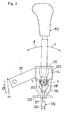
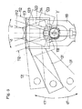
- Figs. 1 through 6 show a shift lever 112 and its support structure of a shifting mechanism according to this invention.
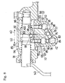
- Fig. 6 shows a transmission case 1 housing a transmission 2 shiftable by the shifting mechanism.
- the transmission case 1 is fixed to the rear of an engine of a tractor acting as a working vehicle.
- the transmission case 1 serves as part of a tractor body.
- the transmission 2 changes the power of the engine to different speeds to be transmitted to rear wheels and front wheels.
- the transmission case 1 supports, between partitions thereof a cylindrical drive shaft 5 and a driven shaft 6 to be rotatable about their respective axes.
- Engine power is transmitted to the drive shaft 5 through a drive gear 7 to rotate the drive shaft 5.
- Rotation of this drive shaft 5 is changed to different speeds in the transmission 2, and transmitted to the driven shaft 6.
- Rotation of the driven shaft 6 is transmitted to the rear wheels and front wheels.
- the drive shaft 5 has a first speed drive gear 11 and a second speed drive gear 12 splined thereto so that the first speed drive gear 11 and second speed drive gear 12 are rotatable with the drive shaft 5. Further, a third speed drive gear 13, a fourth speed drive gear 14, a fifth speed drive gear 15 and a sixth speed drive gear 16 are freely rotatably mounted on the drive shaft 5.
- the driven shaft 6 has a first speed driven gear 21 and a second speed driven gear 22 freely rotatably mounted thereon. Further, the driven shaft 6 has a third speed driven gear 23, a fourth speed driven gear 24, a fifth speed driven gear 25 and a sixth speed driven gear 26 splined thereto, so that the third speed driven gear 23, fourth speed driven gear 24, fifth speed driven gear 25 and sixth speed driven gear 26 are rotatable with the driven shaft 6.
- a first shifter 29 is mounted on the driven shaft 6 between the first speed driven gear 21 and second speed driven gear 22 to be axially slidable through spline engagement.
- a second shifter 30 is mounted on the drive shaft 5 between the third speed drive gear 13 and fourth speed drive gear 14 to be axially slidable through spline engagement.
- a third shifter 31 is mounted on the drive shaft 5 between the fifth speed drive gear 15 and sixth speed drive gear 16 to be axially slidable through spline engagement.
- the transmission case 1 has an upper wall 33 defining an opening 34, and a lid 35 detachably attached to the upper wall 33 for closing the opening 34.
- the lid 35 has supporters 37, 38, 39 and 40 depending therefrom.
- a first shift rod 41 is held between the supporters 37 and 38 to be slidable back and forth.
- a second shift rod 42 is held between the supporters 39 and 38 to be slidable back and forth.
- a third shift rod 43 is held between the supporters 38 and 40 to be slidable back and forth.
- the first shift rod 41 and third shift rod 43 are arranged side by side at substantially the same height to extend in the fore and aft direction.
- a second shift rod 42 is disposed below the first shift rod 41 and coextensive in the fore and aft direction in a vertical relationship with the third shift rod 43.
- the first shift rod 41 has a first shift fork 47 fixedly mounted thereon and engaged with the first shifter 29.
- the first shift fork 47 is slidable (in shifting action) with the first shift rod 41 from a neutral position to a rearward, first speed position and a forward, second speed position.
- the first shifter 29 moves from a neutral position to a rearward, first speed position to mesh with the first speed driven gear 21. Then, rotation of the drive shaft 5 is transmitted to the driven shaft 6 through the first speed drive gear 11, first speed driven gear 21 and first shifter 29 to rotate the driven shaft 6 at a first speed.
- the first shifter 29 moves from the neutral position to a forward, second speed position to mesh with the second speed driven gear 22. Then, rotation of the drive shaft 5 is transmitted to the driven shaft 6 through the second speed drive gear 12, second speed driven gear 22 and second shifter 29 to rotate the driven shaft 6 at a second speed.
- the second shift rod 42 has a second shift fork 48 fixedly mounted thereon and engaged with the second shifter 30.
- the second shift fork 48 is slidable (in shifting action) with the second shift rod 42 from a neutral position to a rearward, third speed position and a forward, fourth speed position.
- the second shifter 30 moves from a neutral position rearward to mesh with the third speed drive gear 13. Then, rotation of the drive shaft 5 is transmitted to the driven shaft 6 through the second shifter 30, third speed drive gear 13 and third speed driven gear 23 and to rotate the driven shaft 6 at a third speed.
- the third shift rod 43 has a third shift fork 49 fixedly mounted thereon and engaged with the third shifter 31.
- the third shift fork 49 is slidable (in shifting action) with the third shift rod 43 from a neutral position to a rearward, fifth speed position and a forward, sixth speed position.
- the third shifter 31 moves from a neutral position rearward to mesh with the fifth speed drive gear 15. Then, rotation of the drive shaft 5 is transmitted to the driven shaft 6 through the third shifter 31, fifth speed drive gear 15 and fifth speed driven gear 25 and to rotate the driven shaft 6 at a fifth speed.
- a first positioning mechanism 51 is provided between the first shift rod 41 and supporter 38 for positioning the first shift rod 41 to the neutral position, rearward first speed position and forward second speed position.
- the first positioning mechanism 51 includes three positioning recesses 52 formed in the first shift rod 41, a holding bore 55 formed in the supporter 38, a pressing spring 56 mounted in the holding bore 55, and a ball 57 for selectively fitting into the positioning recesses 52.
- a second positioning mechanism 58 is provided between the second shift rod 42 and supporter 39 for positioning the second shift rod 42 to the neutral position, rearward third speed position and forward fourth speed position.
- the second positioning mechanism 58 includes three positioning recesses 59 formed in the second shift rod 42, a holding bore 62 formed in the supporter 39, a pressing spring 63 mounted in the holding bore 62, and a ball 64 for selectively fitting into the positioning recesses 59.
- a third positioning mechanism 66 is provided between the third shift rod 43 and supporter 38 for positioning the third shift rod 43 to the neutral position, rearward fifth speed position and forward sixth speed position.
- the third positioning mechanism 66 includes three positioning recesses 67 formed in the third shift rod 43, a holding bore 70 formed in the supporter 38, a pressing spring 71 mounted in the holding bore 70, and a ball 72 for selectively fitting into the positioning recesses 67.
- a lock mechanism 75 is provided between the first shift rod 41, second shift rod 42 and third shift rod 43. When one of the first shift fork 47, second shift fork 48 and third shift fork 49 is operated from the neutral position to one of the speed positions, the lock mechanism 75 locks the other shift forks against movement from the neutral position to the speed positions.
- the lock mechanism 75 includes a first communicating bore 77 formed in the supporter 38 between the first shift rod 41 and second shift rod 42, a second communicating bore 78 formed in the supporter 38 between the second shift rod 42 and the third shift rod 43, three balls 79 mounted in the first communicating bore 77, a ball 80 mounted to the second communicating bore 78, a first engaging recess 81 formed in the first shift rod 41, two second engaging recesses 83 and 84 formed in the second shift rod 42, and a third engaging recess 85 formed in the third shift rod 43.
- the ball 79 becomes disengaged from the second engaging recess 83 of the second shift rod 42, and the other ball 79 engages the first engaging recess 81 of the first shift rod 41, and the ball 80 becomes disengaged from the second engaging recess 84 of the second shift rod 42 and engages the third engaging recess 85 of the third shift rod 43.
- the first shift rod 41 is thereby locked immovable from the neutral position to the first speed position or second speed position, and the third shift rod 43 immovable from the neutral position to the fifth speed position or sixth speed position.
- the ball 80 becomes disengaged from the third engaging recess 85 of the third shift rod 43 and engages the second engaging recess 84 of the second shift rod 42.
- the second shift rod 42 is thereby locked immovable from the neutral position to the third speed position or fourth speed position.
- the lid 35 defines a holder section 89 in the shape of a half cylinder bulging upward and extending transversely of the tractor.
- An interlocking shaft 91 is mounted in the holder section 89 to extend in the transverse direction and to be rotatable about its own axis.
- the interlocking shaft 91 has a shift fork control unit 92 mounted thereon.
- the shift fork control unit 92 has a cylindrical mounting tube 93, and a control element 94 projecting downward from the mounting tube 93.
- the mounting tube 93 is mounted on the interlocking shaft 91 to be slidable right and left and not to be rotatable thereon.
- the shift fork control unit 92 is biased by two pressing springs 96 toward the middle position axially of the interlocking shaft 91. Thus, the shift fork control unit 92 is prevented from inadvertently sliding axially outwardly of the interlocking shaft 91. Further, a positioning mechanism 98 is provided between the interlocking shaft 91 and shift fork control unit 92 for positioning the shift fork control unit 92 transversely of the tractor body.
- the positioning mechanism 98 includes a holding bore 99 formed in the shift fork control unit 92, an annular engaging groove 100 formed in the interlocking shaft 91, a pressing spring 101 mounted in the holding bore 99, and a ball mounted in the holding bore 99.
- the shift fork control unit 92 With the ball 102 engaging the engaging groove 100 under the biasing force of the pressing spring 101, the shift fork control unit 92 is positioned transversely of the tractor body relative to the interlocking shaft 91, in which the shift fork control unit 92 engages a second engagement part 106 to be described hereinafter.
- the shift fork control unit 92 is slidable back and forth (fork-selecting directions) on the interlocking shaft 91, and pivotable for and aft (fork operating directions) about the axis of the interlocking shaft 91.
- the first shift fork 47 has a first engagement part 105 engageable by the shift fork control unit 92.
- the first engagement part 105 is a recess formed in an upper left portion at the proximal end of the first shift fork 47.
- the third shift rod 43 has a third engagement part 105 engageable by the shift fork control unit 92.
- the third engagement part 105 is a recess formed in a right portion of the third shift rod 43.
- the third engagement part 107 is opposed to the first engagement part 105.
- the second shift fork 48 has an engagement piece 108 projecting upward.
- the engagement piece 108 is disposed between the first engagement part 105 of the first shift fork 47 and the third engagement part 107 of the third shift fork 49.
- the engagement piece 108 defines the second engagement part 106 engageable by the shift fork control unit 92.
- the second engagement part 105 is a downward recess formed at an upper end of the engagement piece 108.
- first engagement part 105 of the first shift fork 47, the second engagement part 106 of the second shift fork 48 and the third engagement part 107 of the third shift fork 49 are aligned in the fork-selecting (right and left) direction of the shift fork control unit 92.
- the shift fork control unit 92 is movable right and left for engaging one of the first engagement part 105, second engagement part 106 and third engagement part 107.
- the tractor has one shift lever 112 disposed on a control panel or the like for shifting the transmission 2.
- the shift lever 112 extends upward from a U-shaped rocking support member 114 through a mounting plate 113.
- the rocking support member 114 is attached to a fixed component such as the control panel of the tractor through a first shaft 117, a second shaft 118, a U-shaped fixed support member 119 and a mounting plate 120.
- the mounting plate 120 is fixed to the control panel or the like.
- the fixed support member 119 is fixed such as by welding to the mounting plate 120.
- the first shaft 117 having a first axis X and the second shaft 118 having a second axis Y are integrated into a cross shape.
- the first axis X and second axis Y are located on one plane.
- the first shaft 117 is rotatably supported by the fixed support member 119.
- the second shaft 118 is rotatably supported by the rocking support member 114.
- rocking support member 114, fixed support member 119, first shaft 117 and second shaft 118 constitute a universal joint 121.
- the shift lever 112 is supported to be rockable about the first axis X and second axis Y arranged to cross each other.
- a channel-like interlocking member 123 is fixed such as by welding to the mounting plate 113.
- An L-shaped first connector 124 projects from the interlocking member 123.
- a first interlocking member 126 is connected to the first connector 124 for transmitting a rocking movement about the first axis X of the shift lever 112 to the transmission 2.
- the first interlocking member 126 is in the form of a Bowden cable having an inner wire 127 and an outer wire 108, for example.
- a connection 129 of the first interlocking member 126 to the side of the shift lever 112 is located on or adjacent the second shaft 118.
- a plate-like second connector 131 extends rearward and downward from the interlocking member 123.
- a second interlocking member 132 is connected to the second connector 131 for transmitting a rocking movement about the second axis Y of the shift lever 112 to the transmission 2.
- the second interlocking member 132 is in the form of a Bowden cable, a coupling rod or the like.
- a connection 133 of the second interlocking member 132 to the side of the shift lever 112 is located on or adjacent the first shaft 117.
- a fork selecting shaft 135 is disposed to extend vertically in a position slightly forwardly of the holder section 89 of the lid 35.
- This fork selecting shaft 135 is supported by the lid 35 to be rotatable about a vertical axis.
- the connecting rod 136 extends rearward from a lower end of the fork selecting shaft 135.
- the connecting rod 136 has a bifurcate rear end 137. The bifurcate end 137 receives and pinches an upper part of the control element 94 of the shift fork control unit 92.
- An interlocking rod 139 is mounted on and fixed to an upper end of the fork selecting shaft 135.
- the interlocking rod 139 extends leftward along the upper surface of lid 35 from the fork selecting shaft 135.
- the interlocking rod 139 is biased forward at a position adjacent a distal end thereof by a tension spring 140.
- the other end of the first interlocking member 126 is connected to the distal end of the interlocking rod 139.
- the first connector 124 of the shift lever 112 and the interlocking rod 139 of the fork selecting shaft 135 are operatively connected through the first interlocking member 126.
- the first interlocking member 126 reciprocates in the directions of arrows a1 and b1.
- the connecting rod 136 swings in the same directions as above, to reciprocate the shift fork control unit 92 in directions of arrows a3 and b3 (the right and left, fork selecting directions).
- one end of the interlocking shaft 91 projects from the holder section 89.
- An interlocking rod 143 extends from the outer end of interlocking shaft 91 to be connected to the other end of the second interlocking member 132.
- the second connector 131 of the shift lever 112 and the interlocking rod 143 of the interlocking shaft 91 are operatively connected through the second interlocking member 132.
- the second interlocking member 132 reciprocates in the directions of arrows c1 and d1. This causes the interlocking rod 143 to pivot in directions of arrow c2 and the d2 about the interlocking shaft 91, and the interlocking shaft 91 to rotate back and forth in the same directions.
- the shift fork control unit 92 swings back and forth in the directions of arrows c2 and d2 (fork operating directions) about the axis of the interlocking shaft 91.
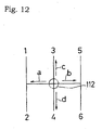
- the shift lever 112 may only be rocked in the directions of arrows a, b, c and d about the first axis X or the second axis Y.
- the shifting operation by the shift lever 112 is made extremely simple.
- the transmission 2 may be shifted easily and reliably.
- the support structure for the shift lever 112 is made very compact.
- the first interlocking member 126 moves in the direction of arrow a1.
- the connecting rod 136 pivots in the same direction to move the shift fork control unit 92 in the direction of arrow a3 (leftward).
- the control element 94 of the shift fork control unit 92 engages the first engagement part 105 of the first shift fork 47.
- the second interlocking member 132 moves in the direction arrow c1.
- This causes the interlocking rod 143 to pivot in direction of the arrow c2 about the interlocking shaft 91 to rotate the interlocking shaft 91 in the same direction.
- the shift fork control unit 92 pivots in the direction of arrow c2 (rearward) about the axis of the interlocking shaft 91. Consequently, the first shift rod 41 (first shift fork 47) moves from the neutral position to the rearward, first speed position.
- the first shifter 29 meshes with the rearward, first speed driven gear 21. Rotation of the drive shaft 5 is transmitted to the driven shaft 6 through the first speed drive gear 11, first speed driven gear 21 and first shifter 29, whereby the driven shaft 6 rotates at the first speed.
- the lock mechanism 75 reliably prevents the first shift fork 47 and third shift fork 49 from being inadvertently operated along with the second shift fork 48.
- the lock mechanism 75 reliably prevents the second shift fork 48 from being inadvertently operated along with the third shift fork 49.
- connection 129 of the first interlocking member 126 to the side of the shift lever 112 is located on or adjacent the second shaft 118.
- the first interlocking member 126 moves to a large extent in the direction of arrow a1 or b1 but the second interlocking member 132 moves only slightly. Consequently, when the shift fork control unit 92 is moved transversely of the tractor body (in the fork selecting direction), the shift fork control unit 92 hardly moves in the fore and aft, fork operating direction. This is effective for reliably preventing inadvertently operations of the shift forks from when the shift lever 112 is rocked in the direction of arrow "a” or "b” about the first axis X.
- connection 133 of the second interlocking member 132 to the side of the shift lever 112 is located on or adjacent the first shaft 117.
- the shift lever 112 is rocked in the direction of arrow "c" or “d” about the second axis Y, as shown in Fig. 5, the second interlocking member 132 moves to a large extent in the direction of arrow c1 or d1, but the first interlocking member 126 moves only slightly. Consequently, when the shift fork control unit 92 is moved longitudinally of the tractor body (in the fork operating direction), the shift fork control unit 92 hardly moves in the transverse, fork selecting direction. This is effective for reliably preventing inadvertently operations of the shift forks from when the shift lever 112 is rocked in the direction of arrow "c" or "d” about the second axis Y.
- the above embodiment includes the three shifters 29, 30 and 31, three shift rods 41, 42 and 43, and three shift forks 47, 48 and 49 to shift the transmission 2 to six gear ratios (first to sixth speeds).
- the number of each of the shifters, shift rods and shift forks may be four or more, with a correspondingly increased number of change speed gears, to shift the transmission 2 to eight (first to eighth speeds) or more stages.
Landscapes
- Engineering & Computer Science (AREA)
- General Engineering & Computer Science (AREA)
- Mechanical Engineering (AREA)
- Gear-Shifting Mechanisms (AREA)
- Arrangement Or Mounting Of Control Devices For Change-Speed Gearing (AREA)
Abstract
Description
Claims (9)
- A shifting mechanism for a transmission having a plurality of gear ratios, withcharacterized in that a combination of rocking movement about the first axis X and rocking movement about the second axis Y of said shift lever determines one of the gear ratios of said transmission (2).a first shaft (117) having a first axis X;a second shaft (118) having a second axis Y and traversing said first shaft to form a cross together; anda shift lever (112) supported by said first shaft and said second shaft to be rockable about said first axis X and said second axis Y;
- A shifting mechanism according to claim 1, characterized in that a connection (129) to the side of said shift lever (112) of a first interlocking member (126) for transmitting the rocking movement about the first axis X of said shift lever (112) to said transmission (2) is located on or adjacent said second shaft (118), and a connection (133) to the side of said shift lever of a second interlocking member (132) for transmitting the rocking movement about the second axis Y of said shift lever to said transmission is located on or adjacent said first shaft (117).
- A shifting mechanism according to claim 1 or 2, characterized in that said first shaft (117) and said second shaft (118) formed integral with each other.
- A shifting mechanism for a transmission having a plurality of gear ratios, witha first shaft (117) having a first axis X;a second shaft (118) having a second axis Y; anda shift lever (112) supported by said first shaft and said second shaft to be rockable about said first axis X and said second axis Y;characterized in that a first shift fork (47), a second shift fork (48) and a third shift fork (49) are provided for operating said transmission (2);a particular gear ratio of said transmission (2) is produced by a combination of rocking movement about the first axis X and rocking movement about the second axis Y of said shift lever; andthe rocking movement about the first axis X of said shift lever (112) selects one of said first shift fork (47), said second shift fork (48) and said third shift fork (49), the selected shift fork (47, 48 or 49) being moved by the rocking movement about the second axis Y of said shift lever, to produce two gear ratios of said transmission.
- A shifting mechanism according to claim 4, characterized in that:a shift fork control unit (92) is provided to be reciprocable in a shift fork selecting direction in response to the rocking movement about the first axis X of said shift lever (112), and reciprocable in a shift fork operating direction in response to the rocking movement about the second axis Y of said shift lever (112);said first shift fork (47) has a first engagement part (105) engageable by said shift fork control unit (92), said second shift fork (48) has a second engagement part (106) engageable by said shift fork control unit (92), and said third shift fork (49) has a third engagement part (107) engageable by said shift fork control unit (92); andsaid first engagement part (105), said second engagement part (106) and said third engagement part (107) are aligned in the shift fork selecting direction, so that the rocking movement about the first axis X of said shift lever (112) causes said shift fork control unit (92) to engage one of said first engagement part (105), said second engagement part (106) and said third engagement part (107).
- A shifting mechanism according to claim 5, characterized in that the shift fork (47, 48 or 49) engaged by said fork control unit (92) is shiftable from a neutral position to two change speed positions by the rocking movement about the second axis Y of said shift lever (112).
- A shifting mechanism according to any one of claims 4 to 6, characterized in that a lock mechanism (75) is provided to be operable, when one of said first shift fork (47), said second shift fork (48) and said third shift fork (49) is operated from a neutral position in to a change speed position, for locking movement of the other shift forks from neutral positions to change speed positions.
- A shifting mechanism according to any one of claims 4 to 7, characterized in that said first shaft (117) and said second shaft (118) traverse each other to form a cross.
- A shifting mechanism according to claim 8, characterized in that said first shaft (117) and said second shaft (118) formed integral with each other.
Applications Claiming Priority (2)
| Application Number | Priority Date | Filing Date | Title |
|---|---|---|---|
| JP2002163487 | 2002-06-04 | ||
| JP2002163487A JP2004009807A (en) | 2002-06-04 | 2002-06-04 | Transmission operating device |
Publications (3)
| Publication Number | Publication Date |
|---|---|
| EP1375974A2 true EP1375974A2 (en) | 2004-01-02 |
| EP1375974A3 EP1375974A3 (en) | 2005-06-08 |
| EP1375974B1 EP1375974B1 (en) | 2007-08-29 |
Family
ID=29717425
Family Applications (1)
| Application Number | Title | Priority Date | Filing Date |
|---|---|---|---|
| EP20030007839 Expired - Lifetime EP1375974B1 (en) | 2002-06-04 | 2003-04-05 | Shifting apparatus for a transmission having a plurality of gear ratios |
Country Status (3)
| Country | Link |
|---|---|
| EP (1) | EP1375974B1 (en) |
| JP (1) | JP2004009807A (en) |
| ES (1) | ES2292870T3 (en) |
Cited By (3)
| Publication number | Priority date | Publication date | Assignee | Title |
|---|---|---|---|---|
| DE102004056778A1 (en) * | 2004-11-24 | 2006-06-01 | Volkswagen Ag | Shift console of a motor vehicle transmission |
| ITMO20130072A1 (en) * | 2013-03-20 | 2014-09-21 | Cnh Italia Spa | CONTROL JOYSTICK FOR A SPEED CHANGE. |
| CN104595472A (en) * | 2015-01-29 | 2015-05-06 | 合肥华骏汽车部件有限公司 | Special purpose part for universal joint pin for shifter |
Families Citing this family (2)
| Publication number | Priority date | Publication date | Assignee | Title |
|---|---|---|---|---|
| KR101013855B1 (en) | 2004-12-23 | 2011-02-14 | 현대자동차주식회사 | Shift lever assembly for manual transmission |
| JP5024187B2 (en) * | 2008-05-30 | 2012-09-12 | 日産自動車株式会社 | Shift lever device and shock absorbing method for shift lever |
Family Cites Families (4)
| Publication number | Priority date | Publication date | Assignee | Title |
|---|---|---|---|---|
| US2197938A (en) * | 1938-09-12 | 1940-04-23 | Clark Equipment Co | Gear shifting mechanism |
| US4129046A (en) * | 1977-03-21 | 1978-12-12 | Caterpillar Tractor Co. | Gear shift control |
| US4152950A (en) * | 1977-05-10 | 1979-05-08 | Incom International Inc. | Differential and push-pull control system |
| DE3784274T2 (en) * | 1986-07-04 | 1993-08-26 | Toyota Motor Co Ltd | SERVO GEAR DEVICE FOR A MANUAL GEARBOX. |
-
2002
- 2002-06-04 JP JP2002163487A patent/JP2004009807A/en active Pending
-
2003
- 2003-04-05 ES ES03007839T patent/ES2292870T3/en not_active Expired - Lifetime
- 2003-04-05 EP EP20030007839 patent/EP1375974B1/en not_active Expired - Lifetime
Cited By (7)
| Publication number | Priority date | Publication date | Assignee | Title |
|---|---|---|---|---|
| DE102004056778A1 (en) * | 2004-11-24 | 2006-06-01 | Volkswagen Ag | Shift console of a motor vehicle transmission |
| ITMO20130072A1 (en) * | 2013-03-20 | 2014-09-21 | Cnh Italia Spa | CONTROL JOYSTICK FOR A SPEED CHANGE. |
| WO2014147105A1 (en) * | 2013-03-20 | 2014-09-25 | Cnh Industrial Italia S.P.A. | A joystick control for a change speed gearbox |
| CN105247250A (en) * | 2013-03-20 | 2016-01-13 | Cnh工业意大利股份公司 | A joystick control for a change speed gearbox |
| CN105247250B (en) * | 2013-03-20 | 2017-06-13 | Cnh工业意大利股份公司 | For the manipulation bar controlling and gear-box of change gear box |
| US10054219B2 (en) | 2013-03-20 | 2018-08-21 | Cnh Industrial America Llc | Joystick control for a change speed gearbox |
| CN104595472A (en) * | 2015-01-29 | 2015-05-06 | 合肥华骏汽车部件有限公司 | Special purpose part for universal joint pin for shifter |
Also Published As
| Publication number | Publication date |
|---|---|
| EP1375974A3 (en) | 2005-06-08 |
| EP1375974B1 (en) | 2007-08-29 |
| ES2292870T3 (en) | 2008-03-16 |
| JP2004009807A (en) | 2004-01-15 |
Similar Documents
| Publication | Publication Date | Title |
|---|---|---|
| US4442730A (en) | Vehicle transmission system and a single lever control device therefor | |
| US4682516A (en) | Vehicular transmission with additional low speed | |
| US5809835A (en) | Manual transmission shift lever | |
| US4266438A (en) | Transmission shift control | |
| US4216680A (en) | Travel speed change apparatus for a farm vehicle | |
| EP1375974B1 (en) | Shifting apparatus for a transmission having a plurality of gear ratios | |
| US4463623A (en) | Tractor transmission structure | |
| GB1598772A (en) | Manual selector mechanisms in change speed gear mechanisms | |
| US5086895A (en) | Brake-actuating mechanism for vehicle parking brakes | |
| CN216009401U (en) | Actuation system in a vehicle transmission system | |
| JP5006778B2 (en) | Power transmission device for tractor | |
| JP2016002934A (en) | Tractor | |
| EP1431620B1 (en) | Manual gearshift lever apparatus | |
| US5016488A (en) | Shift mechanism for engaging sliding gear in manual transmission | |
| EP0447086B1 (en) | Transmission selector mechanism | |
| GB2108602A (en) | Control device for the auxiliary gear reducing unit of a motor vehicle having four driving wheels | |
| JPS5855005B2 (en) | Operation structure of traveling transmission | |
| KR100439885B1 (en) | apparatus for operating a manual transmission | |
| JP2660324B2 (en) | Tiller | |
| JPH11165552A (en) | Speed change device for walking type work machine | |
| JP7264664B2 (en) | manual transmission | |
| JPH081956Y2 (en) | Gear change operation device for work vehicle | |
| CN212717931U (en) | Flexible shaft gear shifting control system | |
| JP4826285B2 (en) | Speed change operation device for work vehicle | |
| JP2003054283A (en) | Gearshift operating device for work vehicles |
Legal Events
| Date | Code | Title | Description |
|---|---|---|---|
| PUAI | Public reference made under article 153(3) epc to a published international application that has entered the european phase |
Free format text: ORIGINAL CODE: 0009012 |
|
| AK | Designated contracting states |
Kind code of ref document: A2 Designated state(s): AT BE BG CH CY CZ DE DK EE ES FI FR GB GR HU IE IT LI LU MC NL PT RO SE SI SK TR |
|
| AX | Request for extension of the european patent |
Extension state: AL LT LV MK |
|
| PUAL | Search report despatched |
Free format text: ORIGINAL CODE: 0009013 |
|
| AK | Designated contracting states |
Kind code of ref document: A3 Designated state(s): AT BE BG CH CY CZ DE DK EE ES FI FR GB GR HU IE IT LI LU MC NL PT RO SE SI SK TR |
|
| AX | Request for extension of the european patent |
Extension state: AL LT LV MK |
|
| RIC1 | Information provided on ipc code assigned before grant |
Ipc: 7F 16H 61/36 B Ipc: 7F 16H 63/20 B Ipc: 7F 16H 59/04 A |
|
| 17P | Request for examination filed |
Effective date: 20050813 |
|
| AKX | Designation fees paid |
Designated state(s): ES FR |
|
| REG | Reference to a national code |
Ref country code: DE Ref legal event code: 8566 |
|
| GRAP | Despatch of communication of intention to grant a patent |
Free format text: ORIGINAL CODE: EPIDOSNIGR1 |
|
| GRAS | Grant fee paid |
Free format text: ORIGINAL CODE: EPIDOSNIGR3 |
|
| GRAA | (expected) grant |
Free format text: ORIGINAL CODE: 0009210 |
|
| AK | Designated contracting states |
Kind code of ref document: B1 Designated state(s): ES FR |
|
| REG | Reference to a national code |
Ref country code: ES Ref legal event code: FG2A Ref document number: 2292870 Country of ref document: ES Kind code of ref document: T3 |
|
| ET | Fr: translation filed | ||
| PLBE | No opposition filed within time limit |
Free format text: ORIGINAL CODE: 0009261 |
|
| STAA | Information on the status of an ep patent application or granted ep patent |
Free format text: STATUS: NO OPPOSITION FILED WITHIN TIME LIMIT |
|
| 26N | No opposition filed |
Effective date: 20080530 |
|
| REG | Reference to a national code |
Ref country code: FR Ref legal event code: PLFP Year of fee payment: 14 |
|
| REG | Reference to a national code |
Ref country code: FR Ref legal event code: PLFP Year of fee payment: 15 |
|
| REG | Reference to a national code |
Ref country code: FR Ref legal event code: PLFP Year of fee payment: 16 |
|
| PGFP | Annual fee paid to national office [announced via postgrant information from national office to epo] |
Ref country code: FR Payment date: 20220308 Year of fee payment: 20 |
|
| PGFP | Annual fee paid to national office [announced via postgrant information from national office to epo] |
Ref country code: ES Payment date: 20220504 Year of fee payment: 20 |
|
| REG | Reference to a national code |
Ref country code: ES Ref legal event code: FD2A Effective date: 20230427 |
|
| PG25 | Lapsed in a contracting state [announced via postgrant information from national office to epo] |
Ref country code: ES Free format text: LAPSE BECAUSE OF EXPIRATION OF PROTECTION Effective date: 20230406 |