EP1375923A2 - Fan mounting system - Google Patents
Fan mounting system Download PDFInfo
- Publication number
- EP1375923A2 EP1375923A2 EP03253408A EP03253408A EP1375923A2 EP 1375923 A2 EP1375923 A2 EP 1375923A2 EP 03253408 A EP03253408 A EP 03253408A EP 03253408 A EP03253408 A EP 03253408A EP 1375923 A2 EP1375923 A2 EP 1375923A2
- Authority
- EP
- European Patent Office
- Prior art keywords
- fan
- flexible metal
- disk
- coupling
- fan drive
- Prior art date
- Legal status (The legal status is an assumption and is not a legal conclusion. Google has not performed a legal analysis and makes no representation as to the accuracy of the status listed.)
- Granted
Links
Images


Classifications
-
- F—MECHANICAL ENGINEERING; LIGHTING; HEATING; WEAPONS; BLASTING
- F04—POSITIVE - DISPLACEMENT MACHINES FOR LIQUIDS; PUMPS FOR LIQUIDS OR ELASTIC FLUIDS
- F04D—NON-POSITIVE-DISPLACEMENT PUMPS
- F04D29/00—Details, component parts, or accessories
- F04D29/26—Rotors specially for elastic fluids
- F04D29/32—Rotors specially for elastic fluids for axial flow pumps
- F04D29/325—Rotors specially for elastic fluids for axial flow pumps for axial flow fans
-
- F—MECHANICAL ENGINEERING; LIGHTING; HEATING; WEAPONS; BLASTING
- F04—POSITIVE - DISPLACEMENT MACHINES FOR LIQUIDS; PUMPS FOR LIQUIDS OR ELASTIC FLUIDS
- F04D—NON-POSITIVE-DISPLACEMENT PUMPS
- F04D29/00—Details, component parts, or accessories
- F04D29/66—Combating cavitation, whirls, noise, vibration or the like; Balancing
- F04D29/661—Combating cavitation, whirls, noise, vibration or the like; Balancing especially adapted for elastic fluid pumps
- F04D29/668—Combating cavitation, whirls, noise, vibration or the like; Balancing especially adapted for elastic fluid pumps damping or preventing mechanical vibrations
-
- Y—GENERAL TAGGING OF NEW TECHNOLOGICAL DEVELOPMENTS; GENERAL TAGGING OF CROSS-SECTIONAL TECHNOLOGIES SPANNING OVER SEVERAL SECTIONS OF THE IPC; TECHNICAL SUBJECTS COVERED BY FORMER USPC CROSS-REFERENCE ART COLLECTIONS [XRACs] AND DIGESTS
- Y10—TECHNICAL SUBJECTS COVERED BY FORMER USPC
- Y10S—TECHNICAL SUBJECTS COVERED BY FORMER USPC CROSS-REFERENCE ART COLLECTIONS [XRACs] AND DIGESTS
- Y10S416/00—Fluid reaction surfaces, i.e. impellers
- Y10S416/50—Vibration damping features
Definitions
- the invention relates generally to cooling systems and more specifically to a flexible metal element fan isolation mount.
- Cooling systems are used on vehicles today to provide cooling to an engine during operation.
- a typical cooling system comprises a combination water pump and fan drive.
- Fan drives are typically driven by the engine crankshaft at a fixed ratio to cool engine coolant as it flows through a radiator. More specifically, a fan that is rigidly mounted to the fan drive generates the airflow as a function of engine crankshaft rotational speed for cooling the radiator.
- vibration caused by the mounting of the fan to the fan drive. This vibration can be detrimental to various components in the cooling system, including the fan hub or water pump.
- the present invention includes the use of a flexible metal disk, or elements, to mount the fan to the fan drive.
- the metal disk is a resilient mounting, and as such reduces vibration levels between the fan and fan drive, thereby preventing damage to various components within the cooling system.
- the flexible metal disk also functions to self align the fan and the fan drive.
- the flexible metal disk is also durable, and therefore offers improved creep and deterioration resistance as compared with typical elastomeric mountings.
- multiple flexible metal disks may be coupled together to provide additional damping as compared with single disk systems.
- a cooling system 20 for an engine 22 is shown as having a coupled water pump 24 and fan drive 26.
- a fan 32 having a series of fan blades 34 is rigidly mounted to the fan drive 26.
- a series of belts 28 convert torque from an engine crankshaft 30 to drive the water pump 24 and fan drive 26 in a manner well known in the art.
- the blades 34 of the coupled fan 32 provide cooling airflow to a radiator (not shown) of the engine 22.
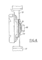
- a flexible metal disk 36 is used to mount the hub 38 of the fan 32 to the fan drive 26.
- a back side 40 of the disk 36 is closely coupled to a corresponding flat side region 42 on the hub 38.
- a plurality of rivets 44 are inserted through a corresponding rivet hole 46 (as shown in Figures 5 and 6) extending through the disk 36 and riveted to the flat side region 42 to secure the disk 36 to the hub 38.
- other types of mounting devices other than rivets 44 may be used to secure the flexible disk 36 to the hub 38.
- An outer end 48 of the fan drive 26 is then inserted through a hollow center region 37 of the hub 38 and reversibly coupled to the fan drive 26 using the flexible metal disk 36. This is accomplished by inserting a bolt 50 through each of a plurality of bolt holes 52 on the disk 36 and securing them within a corresponding mounting hole 54. When properly mounted, the head 56 of each bolt 50 is closely coupled to the front side 58 of the disk 36 opposite the mounting holes 54.
- other types of coupling devices other than bolts 50 secured within a corresponding mounting hole 54 may be used.
- the disk 36 retains torsional rigidity while allowing angular misalignment between the fan 32 and fan drive 26. This prevents the fan 32 from transmitting vibration to the fan drive 26 or vice versa to damage cooling system components such as the water pump 24 or hub 38. The disk 36 also prevents the fan 32 and fan drive 26 from cooperating at a resonant condition.
- multiple disks 36 can be laminated together or otherwise coupled such that the back side 40 of one disk 36 is closely coupled to the front side 58 of the next respective disk 36 and such that the corresponding bolt holes 52 and rivet holes 46 match up to form a multiple disk layer 36A.
- These multiple disk layers 36A may then used to mount the fan 32 to the fan drive 26 in a manner similar to that described above with respect to Figure 3.
- the number of disks 36 in the disk layer 36A increases, the amount of damping achieved between the fan 32 and fan drive 26 correspondingly increases.
- approximately 1-4 disks 36 are used in the disk layer 36A for optimal damping characteristics and cost savings.
- Figures 3 and 4 are not intended to represent a completely accurate side view of Figure 2 having one or multiple disks 36, 36A, instead these Figures are drawn to more clearly illustrate how the rivets 44 and bolts 50 are used to couple the disks 36, 36A to the fan 32 and fan drive 26.
- Figures 5 and 6 illustrate a plan view of the front side 58 of the flexible disk 36 according to two possible preferred embodiments.
- the embodiment according to Figure 5, as shown above in Figures 2-4, is substantially square shaped and continuous (i.e. not segmented), while the embodiment in Figure 6 is substantially circular shaped and continuous.
- the disk 36 preferably comprises a flexible material that has sufficient strength and flexibility at all possible engine operating conditions. The material must resist deterioration and creep throughout the life of the engine 22. Flexible disks 36 made from metals such as aluminum or steel are preferred for these reasons.
- each of the plurality of rivet holes 46 and bolt holes 52 are located symmetrically about the disk 36 such that each rivet hole 46 is located at a comer region 60 of the square shaped front side 58 and such that each bolt hole is located equally between each rivet hole 46 on a side region 62 of the front side 58.
- any flexing that takes place in the disk 36 will occur along each side region 62 between each rivet hole 46 and bolt holt 52 and will therefore not be transmitted as vibration through the cooling system 20.
- the positioning of the rivet holes 46 and bolt holes 52 could be switched and still fall within the spirit of the present invention. Further, the number of rivet holes 46 and/or bolt holes 52 could be increased or decreased and still fall within the spirit of the present invention.
- the shape of the disk 36 could be altered in a wide variety of different manners and still fall within the spirit of the present invention. This is illustrated in Figure 6, in which the disk 36 is substantially circular in shape and comprises a series of rivet holes 46 and bolt holes spaced circumferentially around the disk 36.
- these holes 46, 52 are evenly spaced and alternating around the circumference of the disk 36.
- the holes 46, 52 may be placed in a non-alternating fashion or that the spacing between each respective rivet hole 46 and bolt hole 52 may vary in a symmetrical manner around the circumference of the disk and still fall within the spirit of the present invention.
- any flexing that takes place in the disk 36 will occur between each rivet hole 46 and bolt holt 52 and will therefore not be transmitted as vibration through the cooling system 20.
- the flexible metal disk 36 offers many improvements to other types of mounts that have been used in cooling systems 20.
- the metallic disk 36 retains torsional rigidity but allows angular misalignment of the fan 32 and fan drive 26, thus preventing the fan 32 from transmitting vibration through the fan drive 26 and also preventing the fan drive 26 from transmitting vibration to the fan 32.
- the disk 36 also prevents the fan 32 and fan drive 26 from cooperating in resonant condition, a condition that is potentially detrimental to components of the cooling system 20, including but not limited to the fan hub 38 and the water pump 24.
- the disk 36 is made of flexible metal, it resists deterioration and creep over time as compared with elastomeric mounts.
- the strength and flexible mechanical properties of the flexible metal disk 36 remain relatively constant throughout the variation engine operating temperatures as compared with elastomeric mounts, and as such system reaction to various engine operating temperatures can be more closely controlled.
Landscapes
- Engineering & Computer Science (AREA)
- Mechanical Engineering (AREA)
- General Engineering & Computer Science (AREA)
- Structures Of Non-Positive Displacement Pumps (AREA)
Abstract
Description
Claims (13)
- A fan mounting system comprising:a fan having a hub and a plurality of blades, said hub having a flat side region and a hollow center region;a fan drive having an outer end, said first end coupled within said hollow center region, said outer end having a plurality of mounting holes; andat least one flexible metal disk for coupling said hub to said fan drive, said at least one flexible metal disk used to decrease vibration between said fan and said fan drive and to self center said fan on said fan drive.
- The fan mounting system of claim 1, wherein said at least one flexible metal disk is coupled to said hub by inserting a rivet through each of a respective one of a plurality of rivet holes of each of said at least one flexible metal disks and securing said rivet to said flat side region of said hub.
- The fan mounting system of claim 1, wherein said at least one flexible metal disk is reversibly coupled to said outer end by:coupling a back side of said an outer one of said at least one flexible disks to said flat side region of said hub;inserting a bolt having a head within each of a respective one of a plurality of bolt holes of each of said at least one flexible disks;reversibly securing said bolt within a corresponding one of said plurality of mounting holes.
- The fan mounting system of claim 1, wherein said at least one flexible metal disks comprises at least two flexible metal disks.
- The fan mounting system of claim 1, wherein said at least one flexible metal disks comprises at least one flexible aluminum disk.
- The fan mounting system of claim 1, wherein said at least one flexible metal disks comprises at least one flexible steel disk.
- The fan mounting system of claim 1, wherein said at least one metal disk comprises at least one continuous flexible metal disk.
- A method for improving damping characteristics between a fan and a fan drive in a cooling system comprising:coupling at least one flexible metal disk to the fan; andcoupling said at least one flexible metal disk to the fan drive.
- The method of claim 8, wherein coupling at least one flexible metal disk to the fan comprises:inserting a rivet through each of a respective one of a plurality of rivet holes of each of said at least one flexible metal disks; andsecuring said rivet to a flat side region of a hub of the fan.
- The method of claim 9, wherein coupling said at least one flexible metal disk to the fan drive comprises:inserting a bolt having a head within each of a respective one of a plurality of bolt holes of each of said at least one flexible disks;coupling said fan drive to said at least one flexible metal disk by securing said bolt within a corresponding one of a plurality of mounting holes on the fan drive.
- A method for improving damping characteristics between a fan and a fan drive in a cooling system comprising:forming at least two flexible metal disks, wherein each of said at least two flexible metal disks has a plurality of bolt holes and a plurality of rivet holes;coupling a front side of one of said at least two flexible metal disks to a back side of the next respective one of said at least two metal disks to form a multiple disk layer, said formed multiple disk layer having a first outer side and a second outer side;coupling said first outer side of said multiple disk layer to the fan; andcoupling said second outer side of said multiple disk layer to the fan drive.
- The method of claim 11, wherein coupling said first outer side comprises:closely coupling a first outer side of said multiple disk layer to a flat side region of a hub of the fan;inserting a rivet through each of a respective one of a plurality of rivet holes on each of said at least two flexible metal disks; andsecuring said rivet to said flat side region.
- The method of claim 11, wherein coupling said second outer side comprises:closely coupling said second outer side of said multiple disk layer to said fan drive;inserting a bolt within each of a respective one of a plurality of bolt holes of each of said at least two flexible disks of said multiple disk layer such that a head of said bolt is closely coupled said first outer side of said multiple disk layer;securing said bolt within a corresponding one of a plurality of mounting holes on the fan drive such that said head remains closely coupled to said first outer side.
Applications Claiming Priority (2)
| Application Number | Priority Date | Filing Date | Title |
|---|---|---|---|
| US10/179,654 US6790006B2 (en) | 2002-06-25 | 2002-06-25 | Flexible metal element fan isolation mount |
| US179654 | 2002-06-25 |
Publications (3)
| Publication Number | Publication Date |
|---|---|
| EP1375923A2 true EP1375923A2 (en) | 2004-01-02 |
| EP1375923A3 EP1375923A3 (en) | 2004-09-15 |
| EP1375923B1 EP1375923B1 (en) | 2007-09-26 |
Family
ID=29717909
Family Applications (1)
| Application Number | Title | Priority Date | Filing Date |
|---|---|---|---|
| EP03253408A Expired - Lifetime EP1375923B1 (en) | 2002-06-25 | 2003-05-30 | Fan mounting system |
Country Status (4)
| Country | Link |
|---|---|
| US (1) | US6790006B2 (en) |
| EP (1) | EP1375923B1 (en) |
| JP (1) | JP4430342B2 (en) |
| DE (1) | DE60316507T2 (en) |
Cited By (1)
| Publication number | Priority date | Publication date | Assignee | Title |
|---|---|---|---|---|
| US10577941B2 (en) | 2015-08-05 | 2020-03-03 | Spal Automotive S.R.L. | Axial fan |
Families Citing this family (3)
| Publication number | Priority date | Publication date | Assignee | Title |
|---|---|---|---|---|
| US7063125B2 (en) * | 2003-09-10 | 2006-06-20 | Borgwarner Inc. | Fan penetration feature for in-vehicle testing |
| US9523372B2 (en) | 2010-05-10 | 2016-12-20 | Borgwarner Inc. | Fan with overmolded blades |
| KR101637745B1 (en) * | 2014-11-25 | 2016-07-07 | 현대자동차주식회사 | Radiator having air guide for preventing heat damage in bus |
Family Cites Families (13)
| Publication number | Priority date | Publication date | Assignee | Title |
|---|---|---|---|---|
| DE510569C (en) * | 1930-10-20 | Siemens Schuckertwerke Akt Ges | Impeller for electric vacuum cleaners | |
| DE1284711B (en) | 1965-03-25 | 1968-12-05 | Goetzewerke | Elastic shaft coupling |
| DE2453688A1 (en) | 1974-11-13 | 1976-05-20 | Helmut Hartz | ELASTIC COUPLING |
| US4153389A (en) * | 1978-01-20 | 1979-05-08 | Boyd Keith A | Fan-fan drive assembly |
| JPS5650213A (en) | 1979-09-28 | 1981-05-07 | Aisin Seiki Co Ltd | Coupling for cooling fan |
| US4317339A (en) | 1980-03-05 | 1982-03-02 | Richard Schmidt | Flexible torque coupling for parallel, angular and/or axial misalignment |
| GB2065828B (en) * | 1979-12-18 | 1983-05-18 | Orsiflex Ltd | Flexible couplings |
| JPS5870093A (en) * | 1981-10-23 | 1983-04-26 | Hitachi Ltd | Plastic fan |
| US5221232A (en) | 1989-01-12 | 1993-06-22 | Zero-Max, Inc. | Flexible disc-like coupling element |
| US5219314A (en) | 1990-08-10 | 1993-06-15 | Caterpillar Inc. | Flexible driving transmitting coupling |
| DE4033594C1 (en) | 1990-10-23 | 1992-02-27 | Gkn Automotive Ag, 5200 Siegburg, De | |
| US5271717A (en) | 1992-01-31 | 1993-12-21 | Aisin Kako Kabushiki Kaisha | Coupling fan |
| US5655882A (en) | 1996-05-02 | 1997-08-12 | Engineered Cooling Systems, Inc. | Fan assembly and method |
-
2002
- 2002-06-25 US US10/179,654 patent/US6790006B2/en not_active Expired - Lifetime
-
2003
- 2003-05-30 DE DE60316507T patent/DE60316507T2/en not_active Expired - Lifetime
- 2003-05-30 EP EP03253408A patent/EP1375923B1/en not_active Expired - Lifetime
- 2003-06-24 JP JP2003179190A patent/JP4430342B2/en not_active Expired - Fee Related
Cited By (1)
| Publication number | Priority date | Publication date | Assignee | Title |
|---|---|---|---|---|
| US10577941B2 (en) | 2015-08-05 | 2020-03-03 | Spal Automotive S.R.L. | Axial fan |
Also Published As
| Publication number | Publication date |
|---|---|
| EP1375923A3 (en) | 2004-09-15 |
| JP2004060647A (en) | 2004-02-26 |
| US6790006B2 (en) | 2004-09-14 |
| DE60316507T2 (en) | 2008-07-03 |
| JP4430342B2 (en) | 2010-03-10 |
| DE60316507D1 (en) | 2007-11-08 |
| US20030235500A1 (en) | 2003-12-25 |
| EP1375923B1 (en) | 2007-09-26 |
Similar Documents
| Publication | Publication Date | Title |
|---|---|---|
| US5722909A (en) | Series type decoupling device | |
| EP2282078B1 (en) | Pendulum absorber system | |
| US7585159B2 (en) | Automotive engine-cooling fan assembly | |
| US5352156A (en) | Elastic drive assembly | |
| US6110061A (en) | Device for transmitting rotational power | |
| EP0717211B1 (en) | Flexible plate for transmitting torque | |
| US4929115A (en) | Resilient shaft coupling | |
| US11951824B2 (en) | Shutter device for vehicle | |
| JP2000161389A (en) | Electromagnetic clutch | |
| EP0345080A2 (en) | Molded multi-part generator fan | |
| US6790006B2 (en) | Flexible metal element fan isolation mount | |
| SE442538B (en) | FRICTION COUPLING WITH VIBRATION DIMENSION | |
| JP3542242B2 (en) | Torque converter | |
| US7025187B2 (en) | Electromagnetic clutch assembly | |
| EP1725789B1 (en) | A pulley assembly | |
| EP1367278B1 (en) | Compression elastic coupling device | |
| GB2096237A (en) | Isolation of auxiliary-device drive belt from torsional vibrations of an I.C. engine | |
| US5577972A (en) | Pulley spacer for racing engines | |
| US5465804A (en) | Combination of a power steering pump and air conditioning compressor in an automotive vehicle | |
| JP2002266892A (en) | Driven plate for friction clutch | |
| KR100858095B1 (en) | Power train for clutchless compressor | |
| JP2505056B2 (en) | Coupling fan mounting structure | |
| EP1636512B1 (en) | Engine-driven vehicle | |
| SE512642C2 (en) | Heater with viscous fluid | |
| US20050239561A1 (en) | Inertia ring for suppression of driveshaft radiated noise |
Legal Events
| Date | Code | Title | Description |
|---|---|---|---|
| PUAI | Public reference made under article 153(3) epc to a published international application that has entered the european phase |
Free format text: ORIGINAL CODE: 0009012 |
|
| AK | Designated contracting states |
Kind code of ref document: A2 Designated state(s): AT BE BG CH CY CZ DE DK EE ES FI FR GB GR HU IE IT LI LU MC NL PT RO SE SI SK TR |
|
| AX | Request for extension of the european patent |
Extension state: AL LT LV MK |
|
| PUAL | Search report despatched |
Free format text: ORIGINAL CODE: 0009013 |
|
| AK | Designated contracting states |
Kind code of ref document: A3 Designated state(s): AT BE BG CH CY CZ DE DK EE ES FI FR GB GR HU IE IT LI LU MC NL PT RO SE SI SK TR |
|
| AX | Request for extension of the european patent |
Extension state: AL LT LV MK |
|
| 17P | Request for examination filed |
Effective date: 20041112 |
|
| RAP1 | Party data changed (applicant data changed or rights of an application transferred) |
Owner name: BORGWARNER INC. |
|
| AKX | Designation fees paid |
Designated state(s): DE SE |
|
| 17Q | First examination report despatched |
Effective date: 20060726 |
|
| GRAP | Despatch of communication of intention to grant a patent |
Free format text: ORIGINAL CODE: EPIDOSNIGR1 |
|
| GRAS | Grant fee paid |
Free format text: ORIGINAL CODE: EPIDOSNIGR3 |
|
| GRAA | (expected) grant |
Free format text: ORIGINAL CODE: 0009210 |
|
| AK | Designated contracting states |
Kind code of ref document: B1 Designated state(s): DE SE |
|
| REF | Corresponds to: |
Ref document number: 60316507 Country of ref document: DE Date of ref document: 20071108 Kind code of ref document: P |
|
| REG | Reference to a national code |
Ref country code: SE Ref legal event code: TRGR |
|
| PLBE | No opposition filed within time limit |
Free format text: ORIGINAL CODE: 0009261 |
|
| STAA | Information on the status of an ep patent application or granted ep patent |
Free format text: STATUS: NO OPPOSITION FILED WITHIN TIME LIMIT |
|
| 26N | No opposition filed |
Effective date: 20080627 |
|
| PGFP | Annual fee paid to national office [announced via postgrant information from national office to epo] |
Ref country code: SE Payment date: 20130507 Year of fee payment: 11 |
|
| PG25 | Lapsed in a contracting state [announced via postgrant information from national office to epo] |
Ref country code: SE Free format text: LAPSE BECAUSE OF NON-PAYMENT OF DUE FEES Effective date: 20140531 |
|
| REG | Reference to a national code |
Ref country code: SE Ref legal event code: EUG |
|
| PGFP | Annual fee paid to national office [announced via postgrant information from national office to epo] |
Ref country code: DE Payment date: 20190412 Year of fee payment: 17 |
|
| REG | Reference to a national code |
Ref country code: DE Ref legal event code: R119 Ref document number: 60316507 Country of ref document: DE |
|
| PG25 | Lapsed in a contracting state [announced via postgrant information from national office to epo] |
Ref country code: DE Free format text: LAPSE BECAUSE OF NON-PAYMENT OF DUE FEES Effective date: 20201201 |