EP1375899A2 - Vehicle intake manifold having an integrated fuel rail and volume adjacent thereto - Google Patents
Vehicle intake manifold having an integrated fuel rail and volume adjacent thereto Download PDFInfo
- Publication number
- EP1375899A2 EP1375899A2 EP03013301A EP03013301A EP1375899A2 EP 1375899 A2 EP1375899 A2 EP 1375899A2 EP 03013301 A EP03013301 A EP 03013301A EP 03013301 A EP03013301 A EP 03013301A EP 1375899 A2 EP1375899 A2 EP 1375899A2
- Authority
- EP
- European Patent Office
- Prior art keywords
- intake manifold
- fuel rail
- volume
- fuel
- recited
- Prior art date
- Legal status (The legal status is an assumption and is not a legal conclusion. Google has not performed a legal analysis and makes no representation as to the accuracy of the status listed.)
- Granted
Links
Images

Classifications
-
- F—MECHANICAL ENGINEERING; LIGHTING; HEATING; WEAPONS; BLASTING
- F02—COMBUSTION ENGINES; HOT-GAS OR COMBUSTION-PRODUCT ENGINE PLANTS
- F02M—SUPPLYING COMBUSTION ENGINES IN GENERAL WITH COMBUSTIBLE MIXTURES OR CONSTITUENTS THEREOF
- F02M35/00—Combustion-air cleaners, air intakes, intake silencers, or induction systems specially adapted for, or arranged on, internal-combustion engines
- F02M35/10—Air intakes; Induction systems
- F02M35/10314—Materials for intake systems
- F02M35/10321—Plastics; Composites; Rubbers
-
- F—MECHANICAL ENGINEERING; LIGHTING; HEATING; WEAPONS; BLASTING
- F02—COMBUSTION ENGINES; HOT-GAS OR COMBUSTION-PRODUCT ENGINE PLANTS
- F02M—SUPPLYING COMBUSTION ENGINES IN GENERAL WITH COMBUSTIBLE MIXTURES OR CONSTITUENTS THEREOF
- F02M35/00—Combustion-air cleaners, air intakes, intake silencers, or induction systems specially adapted for, or arranged on, internal-combustion engines
- F02M35/10—Air intakes; Induction systems
- F02M35/10006—Air intakes; Induction systems characterised by the position of elements of the air intake system in direction of the air intake flow, i.e. between ambient air inlet and supply to the combustion chamber
- F02M35/10026—Plenum chambers
- F02M35/10032—Plenum chambers specially shaped or arranged connecting duct between carburettor or air inlet duct and the plenum chamber; specially positioned carburettors or throttle bodies with respect to the plenum chamber
-
- F—MECHANICAL ENGINEERING; LIGHTING; HEATING; WEAPONS; BLASTING
- F02—COMBUSTION ENGINES; HOT-GAS OR COMBUSTION-PRODUCT ENGINE PLANTS
- F02M—SUPPLYING COMBUSTION ENGINES IN GENERAL WITH COMBUSTIBLE MIXTURES OR CONSTITUENTS THEREOF
- F02M35/00—Combustion-air cleaners, air intakes, intake silencers, or induction systems specially adapted for, or arranged on, internal-combustion engines
- F02M35/10—Air intakes; Induction systems
- F02M35/10006—Air intakes; Induction systems characterised by the position of elements of the air intake system in direction of the air intake flow, i.e. between ambient air inlet and supply to the combustion chamber
- F02M35/10078—Connections of intake systems to the engine
- F02M35/10085—Connections of intake systems to the engine having a connecting piece, e.g. a flange, between the engine and the air intake being foreseen with a throttle valve, fuel injector, mixture ducts or the like
-
- F—MECHANICAL ENGINEERING; LIGHTING; HEATING; WEAPONS; BLASTING
- F02—COMBUSTION ENGINES; HOT-GAS OR COMBUSTION-PRODUCT ENGINE PLANTS
- F02M—SUPPLYING COMBUSTION ENGINES IN GENERAL WITH COMBUSTIBLE MIXTURES OR CONSTITUENTS THEREOF
- F02M35/00—Combustion-air cleaners, air intakes, intake silencers, or induction systems specially adapted for, or arranged on, internal-combustion engines
- F02M35/10—Air intakes; Induction systems
- F02M35/10091—Air intakes; Induction systems characterised by details of intake ducts: shapes; connections; arrangements
- F02M35/10131—Ducts situated in more than one plane; Ducts of one plane crossing ducts of another plane
-
- F—MECHANICAL ENGINEERING; LIGHTING; HEATING; WEAPONS; BLASTING
- F02—COMBUSTION ENGINES; HOT-GAS OR COMBUSTION-PRODUCT ENGINE PLANTS
- F02M—SUPPLYING COMBUSTION ENGINES IN GENERAL WITH COMBUSTIBLE MIXTURES OR CONSTITUENTS THEREOF
- F02M35/00—Combustion-air cleaners, air intakes, intake silencers, or induction systems specially adapted for, or arranged on, internal-combustion engines
- F02M35/10—Air intakes; Induction systems
- F02M35/10091—Air intakes; Induction systems characterised by details of intake ducts: shapes; connections; arrangements
- F02M35/10144—Connections of intake ducts to each other or to another device
-
- F—MECHANICAL ENGINEERING; LIGHTING; HEATING; WEAPONS; BLASTING
- F02—COMBUSTION ENGINES; HOT-GAS OR COMBUSTION-PRODUCT ENGINE PLANTS
- F02M—SUPPLYING COMBUSTION ENGINES IN GENERAL WITH COMBUSTIBLE MIXTURES OR CONSTITUENTS THEREOF
- F02M35/00—Combustion-air cleaners, air intakes, intake silencers, or induction systems specially adapted for, or arranged on, internal-combustion engines
- F02M35/10—Air intakes; Induction systems
- F02M35/10209—Fluid connections to the air intake system; their arrangement of pipes, valves or the like
- F02M35/10216—Fuel injectors; Fuel pipes or rails; Fuel pumps or pressure regulators
-
- F—MECHANICAL ENGINEERING; LIGHTING; HEATING; WEAPONS; BLASTING
- F02—COMBUSTION ENGINES; HOT-GAS OR COMBUSTION-PRODUCT ENGINE PLANTS
- F02M—SUPPLYING COMBUSTION ENGINES IN GENERAL WITH COMBUSTIBLE MIXTURES OR CONSTITUENTS THEREOF
- F02M35/00—Combustion-air cleaners, air intakes, intake silencers, or induction systems specially adapted for, or arranged on, internal-combustion engines
- F02M35/10—Air intakes; Induction systems
- F02M35/10242—Devices or means connected to or integrated into air intakes; Air intakes combined with other engine or vehicle parts
- F02M35/10288—Air intakes combined with another engine part, e.g. cylinder head cover or being cast in one piece with the exhaust manifold, cylinder head or engine block
-
- F—MECHANICAL ENGINEERING; LIGHTING; HEATING; WEAPONS; BLASTING
- F02—COMBUSTION ENGINES; HOT-GAS OR COMBUSTION-PRODUCT ENGINE PLANTS
- F02M—SUPPLYING COMBUSTION ENGINES IN GENERAL WITH COMBUSTIBLE MIXTURES OR CONSTITUENTS THEREOF
- F02M35/00—Combustion-air cleaners, air intakes, intake silencers, or induction systems specially adapted for, or arranged on, internal-combustion engines
- F02M35/10—Air intakes; Induction systems
- F02M35/104—Intake manifolds
- F02M35/112—Intake manifolds for engines with cylinders all in one line
-
- F—MECHANICAL ENGINEERING; LIGHTING; HEATING; WEAPONS; BLASTING
- F02—COMBUSTION ENGINES; HOT-GAS OR COMBUSTION-PRODUCT ENGINE PLANTS
- F02M—SUPPLYING COMBUSTION ENGINES IN GENERAL WITH COMBUSTIBLE MIXTURES OR CONSTITUENTS THEREOF
- F02M35/00—Combustion-air cleaners, air intakes, intake silencers, or induction systems specially adapted for, or arranged on, internal-combustion engines
- F02M35/12—Intake silencers ; Sound modulation, transmission or amplification
- F02M35/1255—Intake silencers ; Sound modulation, transmission or amplification using resonance
-
- F—MECHANICAL ENGINEERING; LIGHTING; HEATING; WEAPONS; BLASTING
- F02—COMBUSTION ENGINES; HOT-GAS OR COMBUSTION-PRODUCT ENGINE PLANTS
- F02M—SUPPLYING COMBUSTION ENGINES IN GENERAL WITH COMBUSTIBLE MIXTURES OR CONSTITUENTS THEREOF
- F02M69/00—Low-pressure fuel-injection apparatus ; Apparatus with both continuous and intermittent injection; Apparatus injecting different types of fuel
- F02M69/04—Injectors peculiar thereto
- F02M69/042—Positioning of injectors with respect to engine, e.g. in the air intake conduit
- F02M69/044—Positioning of injectors with respect to engine, e.g. in the air intake conduit for injecting into the intake conduit downstream of an air throttle valve
-
- F—MECHANICAL ENGINEERING; LIGHTING; HEATING; WEAPONS; BLASTING
- F02—COMBUSTION ENGINES; HOT-GAS OR COMBUSTION-PRODUCT ENGINE PLANTS
- F02M—SUPPLYING COMBUSTION ENGINES IN GENERAL WITH COMBUSTIBLE MIXTURES OR CONSTITUENTS THEREOF
- F02M69/00—Low-pressure fuel-injection apparatus ; Apparatus with both continuous and intermittent injection; Apparatus injecting different types of fuel
- F02M69/46—Details, component parts or accessories not provided for in, or of interest apart from, the apparatus covered by groups F02M69/02 - F02M69/44
- F02M69/462—Arrangement of fuel conduits, e.g. with valves for maintaining pressure in the pipes after the engine being shut-down
- F02M69/465—Arrangement of fuel conduits, e.g. with valves for maintaining pressure in the pipes after the engine being shut-down of fuel rails
Definitions
- the present invention relates to a non-metallic vehicle air intake manifold and, more particularly, to an intake manifold which integrates a fuel rail and adjacent volume within the heretofore unused space within the intake manifold.
- An air intake manifold distributes air to a vehicle engine's cylinders.
- the manifold is located on the engine in the engine compartment of a vehicle.
- the manifold is in close proximity to various electrical components of the vehicle engine such as fuel injectors, electric throttle body, throttle position sensors, idle air controller, and air temperature and pressure sensors.
- Other components are also located within the engine compartment such as fuel rails, air cleaners and other air induction components.
- the intake manifold primarily includes a plurality of runners which communicate and distribute air to the engine cylinders.
- the runners are of a particular geometry to assure proper air flow thereto.
- non-metallic materials are used in the manufacture of air intake manifolds.
- the intake manifolds are manufactured separate from the fuel rail as the fuel rail is commonly manufactured of metal to minimize permeation of fuel therefrom.
- the intake manifold is often shaped to accommodate the fuel rail location while assuring proper air flow to the engine cylinders and precise fuel delivery.
- the intake manifold may therefore be relatively large in size and include numerous components, such as sensors, actuators, wiring harness and associated fasteners.
- the relatively large air intake manifold, combined with the numerous associated components, provides a rather complicated molded and time consuming multiple assembly process.
- the engine compartment must therefore be designed to accommodate these numerous, rather large components. This may disadvantageously limit the desired design of the vehicle and increase labor cost and cycle time.
- the intake manifold according to the present invention provides an integral fuel rail at least partially surrounded by a volume.
- the volume being adjacent the fuel rail, minimizes the permeation of fuel out of the fuel rail. That is, the fuel must not only permeate through a surface of the fuel rail, but must additionally permeate a surface which defines the volume to fully escape the intake manifold.
- Manufacture of the fuel rail as integral to the non-metallic intake manifold with minimization of fuel escape through permeation is therefore advantageously provided by the present invention.
- the volume may alternatively or additionally be utilized to contain an air induction component such as an acoustic resonator, charcoal canister, air cleaner, or the like which has heretofore been located adjacent the intake manifold.
- an air induction component such as an acoustic resonator, charcoal canister, air cleaner, or the like which has heretofore been located adjacent the intake manifold.
- the present invention therefore provides an air intake manifold which integrate multiple airflow related components without minimizing the air distributing capabilities thereof.
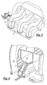
- Figure 1 illustrates a general perspective view of an intake manifold assembly 10 mounted to an internal combustion engine (illustrated schematically at 12) to provide for regulation of an air fuel mixture.
- the manifold is preferably a non-metallic molded plastic manifold, which is manufactured of a plurality of sections 10a, 10b, 10c ( Figure 2). It should be understood that any number of sections and interface locations will benefit from the present invention.
- the intake manifold 10 includes a fuel rail 14 which is preferably directly molded therein. That is, the fuel rail 14 is integrally molded into the intake manifold 10 ( Figure 3) and forms a portion thereof.
- the fuel rail 14 is preferably pentagonal in cross-sectional shape; however, other shapes will benefit from the present invention.
- the fuel rail 14 communicates with each of a plurality of engine cylinders (illustrated schematically at 16) through a fuel injector 18. Fuel fills the fuel rail and is communicated into each engine cylinder 16 through operation of the fuel injectors 18 (also illustrated in Figure 4).
- the fuel injectors 16 regulate the amount of fuel mixed with air drawn through the intake manifold 10 and into the engine 12.
- a runner 20 communicates the airflow to each engine cylinder 16 within the engine 12.
- a volume 22 Adjacent the fuel rail 14 is a volume 22.
- the volume 22 is integrally molded into the intake manifold 10 and forms a portion thereof.
- the volume 22 is located at least above the fuel rail 14, however, any number of volumes either continuous or discontinuous will benefit from the present invention. Although preferably located above, the volume 22 may alternatively or additionally surround any side and/or portion of the fuel rail 14. It should be understood that relative positional terms such as “forward,” “aft,” “upper,” “lower,” “above,” “below,” and the like are with reference to the normal operational attitude of the vehicle and should not be considered otherwise limiting.
- the volume 22, being adjacent the fuel rail 14, minimizes the permeation of fuel out of the fuel rail 14. That is, the fuel must not only permeate through a surface 24 between the fuel rail 14 and the volume 22, but must additionally permeate a surface which defines the volume 22.
- Manufacture of the fuel rail 14 as integral to the non-metallic intake manifold 10 with-minimization of fuel escape through permeation is therefore advantageously provided by the present invention.
- the volume 22 is sealed and may therefore be utilized as a storage space.
- the volume 22 may alternatively or additionally be utilized to contain an air induction component 24 such as an acoustic resonator, charcoal canister, air cleaner, or the like which has heretofore been located adjacent the intake manifold. A more compact arrangement is therefore provided as the space of the intake manifold is more effectively utilized.
Landscapes
- Engineering & Computer Science (AREA)
- Chemical & Material Sciences (AREA)
- Combustion & Propulsion (AREA)
- Mechanical Engineering (AREA)
- General Engineering & Computer Science (AREA)
- Fuel-Injection Apparatus (AREA)
- Cooling, Air Intake And Gas Exhaust, And Fuel Tank Arrangements In Propulsion Units (AREA)
Abstract
Description
Claims (12)
- A non-metallic intake manifold assembly comprising:an intake manifold comprising a plurality of runners, said intake manifold formed of a non-metallic material; anda fuel rail integrally formed within said intake manifold, said fuel rail formed of said non-metallic material.
- The intake manifold as recited in claim 1, wherein said fuel rail is adjacent each of said plurality of runners.
- The intake manifold as recited in claim 1, wherein said fuel rail is pentagonal is cross-section.
- The intake manifold as recited in claim 1, further comprising a plurality of fuel injectors in communication with said fuel rail.
- The intake manifold as recited in claim 1, further comprising a volume formed within said intake manifold, said volume adjacent said fuel rail.
- The intake manifold as recited in claim 1, further comprising a volume formed within said intake manifold, said volume sharing a wall with said fuel rail.
- The intake manifold as recited in claim 1, further comprising a sealed volume formed within said intake manifold, said volume adjacent and separate from said fuel rail.
- The intake manifold as recited in claim 1, further comprising a volume formed above said intake manifold.
- The intake manifold as recited in claim 1, further comprising a volume formed within said intake manifold, said volume adjacent said fuel rail and containing an air induction component.
- A non-metallic intake manifold assembly comprising:an intake manifold comprising a plurality of runners, said intake manifold formed of a non-metallic material;a fuel rail integrally formed within said intake manifold, said fuel rail formed of said non-metallic material; anda volume formed within said intake manifold and formed of said non-metallic material, said volume adjacent said fuel rail.
- The intake manifold as recited in claim 10, wherein said volume shares a wall with said fuel rail.
- The intake manifold as recited in claim 10, further comprising an air induction component contained within said volume.
Applications Claiming Priority (8)
| Application Number | Priority Date | Filing Date | Title |
|---|---|---|---|
| US38959502P | 2002-06-18 | 2002-06-18 | |
| US38958202P | 2002-06-18 | 2002-06-18 | |
| US389595P | 2002-06-18 | ||
| US389582P | 2002-06-18 | ||
| US38982402P | 2002-06-19 | 2002-06-19 | |
| US389824P | 2002-06-19 | ||
| US10/439,523 US6758191B2 (en) | 2002-06-18 | 2003-05-16 | Vehicle intake manifold having an integrated fuel rail and volume adjacent thereto |
| US439523 | 2003-05-16 |
Publications (3)
| Publication Number | Publication Date |
|---|---|
| EP1375899A2 true EP1375899A2 (en) | 2004-01-02 |
| EP1375899A3 EP1375899A3 (en) | 2006-05-31 |
| EP1375899B1 EP1375899B1 (en) | 2010-10-27 |
Family
ID=29718699
Family Applications (1)
| Application Number | Title | Priority Date | Filing Date |
|---|---|---|---|
| EP03013301A Expired - Lifetime EP1375899B1 (en) | 2002-06-18 | 2003-06-12 | Vehicle intake manifold having an integrated fuel rail and volume adjacent thereto |
Country Status (3)
| Country | Link |
|---|---|
| US (1) | US6758191B2 (en) |
| EP (1) | EP1375899B1 (en) |
| DE (1) | DE60334658D1 (en) |
Cited By (3)
| Publication number | Priority date | Publication date | Assignee | Title |
|---|---|---|---|---|
| FR2909731A1 (en) * | 2006-12-08 | 2008-06-13 | Renault Sas | Internal combustion engine's part manufacturing method for vehicle, involves incorporating part of common fuel supply ramp into injection tubes by injecting synthetic material compatible with that of conduit of air intake splitter |
| FR3044048A1 (en) * | 2015-11-20 | 2017-05-26 | Renault Sas | IMPROVED AIR DISTRIBUTION OF A VEHICLE |
| US12497937B2 (en) | 2022-05-30 | 2025-12-16 | Cummins Inc. | Intake manifold with integrated fuel return passage |
Families Citing this family (4)
| Publication number | Priority date | Publication date | Assignee | Title |
|---|---|---|---|---|
| JP4020058B2 (en) * | 2003-10-10 | 2007-12-12 | 日産自動車株式会社 | Intake device for internal combustion engine |
| US6840221B1 (en) * | 2003-12-23 | 2005-01-11 | International Engine Intellectual Property Company, Llc | Runnerless engine intake manifold having integral fuel delivery groove or bore |
| US20050133009A1 (en) * | 2003-12-23 | 2005-06-23 | Robert Rowells | Runnerless engine intake manifold having integral fuel delivery groove |
| US9222433B2 (en) | 2011-10-31 | 2015-12-29 | Cummins Power Generation Ip, Inc. | Genset fuel injection system |
Family Cites Families (9)
| Publication number | Priority date | Publication date | Assignee | Title |
|---|---|---|---|---|
| US4776313A (en) * | 1987-06-01 | 1988-10-11 | Ford Motor Company | Compact integrated engine induction air/fuel system |
| US5163406A (en) * | 1990-08-07 | 1992-11-17 | Siemens Automotive L.P. | Intake manifold/fuel rail |
| DE9410232U1 (en) * | 1994-06-27 | 1995-11-02 | Robert Bosch Gmbh, 70469 Stuttgart | Fuel injection device for internal combustion engines |
| JP3720402B2 (en) * | 1995-02-17 | 2005-11-30 | ヤマハマリン株式会社 | Fuel-injection outboard motor |
| US5682859A (en) * | 1996-01-22 | 1997-11-04 | Siemens Automotive Corporation | Method and arrangement for mounting fuel rails |
| US5771863A (en) * | 1996-10-11 | 1998-06-30 | Siemens Electric Limited | Integrated intake manifold and fuel rail with enclosed fuel filter |
| US6186106B1 (en) * | 1997-12-29 | 2001-02-13 | Visteon Global Technologies, Inc. | Apparatus for routing electrical signals in an engine |
| US6520154B2 (en) * | 1998-02-20 | 2003-02-18 | Delphi Technologies, Inc. | Side feed fuel injector and integrated fuel rail/intake manifold |
| US6308686B1 (en) * | 1999-11-18 | 2001-10-30 | Siemens Canada Limited | Intake manifold with internal fuel rail and injectors |
-
2003
- 2003-05-16 US US10/439,523 patent/US6758191B2/en not_active Expired - Lifetime
- 2003-06-12 DE DE60334658T patent/DE60334658D1/en not_active Expired - Lifetime
- 2003-06-12 EP EP03013301A patent/EP1375899B1/en not_active Expired - Lifetime
Cited By (3)
| Publication number | Priority date | Publication date | Assignee | Title |
|---|---|---|---|---|
| FR2909731A1 (en) * | 2006-12-08 | 2008-06-13 | Renault Sas | Internal combustion engine's part manufacturing method for vehicle, involves incorporating part of common fuel supply ramp into injection tubes by injecting synthetic material compatible with that of conduit of air intake splitter |
| FR3044048A1 (en) * | 2015-11-20 | 2017-05-26 | Renault Sas | IMPROVED AIR DISTRIBUTION OF A VEHICLE |
| US12497937B2 (en) | 2022-05-30 | 2025-12-16 | Cummins Inc. | Intake manifold with integrated fuel return passage |
Also Published As
| Publication number | Publication date |
|---|---|
| US20030230286A1 (en) | 2003-12-18 |
| US6758191B2 (en) | 2004-07-06 |
| EP1375899B1 (en) | 2010-10-27 |
| EP1375899A3 (en) | 2006-05-31 |
| DE60334658D1 (en) | 2010-12-09 |
Similar Documents
| Publication | Publication Date | Title |
|---|---|---|
| EP1750004B1 (en) | Resin intake manifold | |
| US5533485A (en) | Fuel injection device for internal combustion engines | |
| EP1063423B1 (en) | Internal Combustion Engine with an Orientation Apparatus for Orienting a Fuel Injector with respect to the Manifold or the Head, and the Corresponding Method of Orienting | |
| US6167855B1 (en) | Integrated air-fuel module and assembly method | |
| GB2125893A (en) | Fuel rail | |
| KR100986063B1 (en) | Car Canister | |
| US6758191B2 (en) | Vehicle intake manifold having an integrated fuel rail and volume adjacent thereto | |
| GB2352774A (en) | Integrated air induction module for gasoline engines | |
| US20150089910A1 (en) | Air filter | |
| EP1296036A3 (en) | Motorcycle having an internal combustion engine | |
| JPH1182197A (en) | Intake device for internal combustion engine | |
| US20050252489A1 (en) | Variable octane duel fuel delivery system | |
| EP1375897B1 (en) | Vehicle non-metallic intake manifold having an integrated metallic fuel rail | |
| US6769410B2 (en) | Integrated fuel module wire harness and carrier gasket for vehicle intake manifold | |
| RU117097U1 (en) | COAL FILTER, PERFORMED AS ONE WHOLE | |
| CN106246401A (en) | A kind of LD-diesel housing construction | |
| EP1600625A1 (en) | Vehicle fuel supply construction | |
| EP1803924B1 (en) | Fuel injection system for engine | |
| JP2005048736A (en) | Internal combustion engine surge tank | |
| US6089202A (en) | Air-supply module for internal combustion engine | |
| JP2002070671A (en) | Intake manifold for multi-directional fuel injection | |
| JP2000282993A (en) | Reserve structure of fuel supply device | |
| US5797381A (en) | Air assist device of an engine | |
| JP3757432B2 (en) | Fuel supply device and delivery pipe | |
| US20040255891A1 (en) | Low-profile intake manifold |
Legal Events
| Date | Code | Title | Description |
|---|---|---|---|
| PUAI | Public reference made under article 153(3) epc to a published international application that has entered the european phase |
Free format text: ORIGINAL CODE: 0009012 |
|
| AK | Designated contracting states |
Kind code of ref document: A2 Designated state(s): AT BE BG CH CY CZ DE DK EE ES FI FR GB GR HU IE IT LI LU MC NL PT RO SE SI SK TR |
|
| AX | Request for extension of the european patent |
Extension state: AL LT LV MK |
|
| PUAL | Search report despatched |
Free format text: ORIGINAL CODE: 0009013 |
|
| AK | Designated contracting states |
Kind code of ref document: A3 Designated state(s): AT BE BG CH CY CZ DE DK EE ES FI FR GB GR HU IE IT LI LU MC NL PT RO SE SI SK TR |
|
| AX | Request for extension of the european patent |
Extension state: AL LT LV MK |
|
| 17P | Request for examination filed |
Effective date: 20060719 |
|
| AKX | Designation fees paid |
Designated state(s): DE GB |
|
| 17Q | First examination report despatched |
Effective date: 20070426 |
|
| GRAP | Despatch of communication of intention to grant a patent |
Free format text: ORIGINAL CODE: EPIDOSNIGR1 |
|
| GRAC | Information related to communication of intention to grant a patent modified |
Free format text: ORIGINAL CODE: EPIDOSCIGR1 |
|
| GRAS | Grant fee paid |
Free format text: ORIGINAL CODE: EPIDOSNIGR3 |
|
| GRAA | (expected) grant |
Free format text: ORIGINAL CODE: 0009210 |
|
| AK | Designated contracting states |
Kind code of ref document: B1 Designated state(s): DE GB |
|
| REG | Reference to a national code |
Ref country code: GB Ref legal event code: FG4D |
|
| REF | Corresponds to: |
Ref document number: 60334658 Country of ref document: DE Date of ref document: 20101209 Kind code of ref document: P |
|
| PLBE | No opposition filed within time limit |
Free format text: ORIGINAL CODE: 0009261 |
|
| STAA | Information on the status of an ep patent application or granted ep patent |
Free format text: STATUS: NO OPPOSITION FILED WITHIN TIME LIMIT |
|
| 26N | No opposition filed |
Effective date: 20110728 |
|
| REG | Reference to a national code |
Ref country code: DE Ref legal event code: R097 Ref document number: 60334658 Country of ref document: DE Effective date: 20110728 |
|
| PGFP | Annual fee paid to national office [announced via postgrant information from national office to epo] |
Ref country code: GB Payment date: 20160630 Year of fee payment: 14 |
|
| PGFP | Annual fee paid to national office [announced via postgrant information from national office to epo] |
Ref country code: DE Payment date: 20160831 Year of fee payment: 14 |
|
| REG | Reference to a national code |
Ref country code: DE Ref legal event code: R119 Ref document number: 60334658 Country of ref document: DE |
|
| GBPC | Gb: european patent ceased through non-payment of renewal fee |
Effective date: 20170612 |
|
| PG25 | Lapsed in a contracting state [announced via postgrant information from national office to epo] |
Ref country code: DE Free format text: LAPSE BECAUSE OF NON-PAYMENT OF DUE FEES Effective date: 20180103 Ref country code: GB Free format text: LAPSE BECAUSE OF NON-PAYMENT OF DUE FEES Effective date: 20170612 |