EP1375885A1 - Procédé de traitement des gaz d'échappement d'un moteur à combustion à essence - Google Patents
Procédé de traitement des gaz d'échappement d'un moteur à combustion à essence Download PDFInfo
- Publication number
- EP1375885A1 EP1375885A1 EP03291414A EP03291414A EP1375885A1 EP 1375885 A1 EP1375885 A1 EP 1375885A1 EP 03291414 A EP03291414 A EP 03291414A EP 03291414 A EP03291414 A EP 03291414A EP 1375885 A1 EP1375885 A1 EP 1375885A1
- Authority
- EP
- European Patent Office
- Prior art keywords
- catalyst
- richness
- temperature
- hydrocarbons
- treatment
- Prior art date
- Legal status (The legal status is an assumption and is not a legal conclusion. Google has not performed a legal analysis and makes no representation as to the accuracy of the status listed.)
- Granted
Links
- 238000000034 method Methods 0.000 title claims abstract description 17
- 238000002485 combustion reaction Methods 0.000 title claims abstract description 10
- 239000003054 catalyst Substances 0.000 claims abstract description 63
- 229930195733 hydrocarbon Natural products 0.000 claims abstract description 50
- 150000002430 hydrocarbons Chemical class 0.000 claims abstract description 50
- 239000007789 gas Substances 0.000 claims abstract description 21
- 239000000203 mixture Substances 0.000 claims abstract description 16
- 239000004215 Carbon black (E152) Substances 0.000 claims abstract description 15
- 238000011144 upstream manufacturing Methods 0.000 claims abstract description 13
- UGFAIRIUMAVXCW-UHFFFAOYSA-N Carbon monoxide Chemical compound [O+]#[C-] UGFAIRIUMAVXCW-UHFFFAOYSA-N 0.000 claims description 19
- 229910002091 carbon monoxide Inorganic materials 0.000 claims description 18
- 238000002347 injection Methods 0.000 claims description 14
- 239000007924 injection Substances 0.000 claims description 14
- 239000000446 fuel Substances 0.000 claims description 13
- 238000006243 chemical reaction Methods 0.000 claims description 6
- 230000037452 priming Effects 0.000 claims description 6
- QVGXLLKOCUKJST-UHFFFAOYSA-N atomic oxygen Chemical compound [O] QVGXLLKOCUKJST-UHFFFAOYSA-N 0.000 claims description 5
- 239000001301 oxygen Substances 0.000 claims description 5
- 229910052760 oxygen Inorganic materials 0.000 claims description 5
- OKTJSMMVPCPJKN-UHFFFAOYSA-N Carbon Chemical compound [C] OKTJSMMVPCPJKN-UHFFFAOYSA-N 0.000 claims description 2
- 229910052799 carbon Inorganic materials 0.000 claims description 2
- MWUXSHHQAYIFBG-UHFFFAOYSA-N nitrogen oxide Inorganic materials O=[N] MWUXSHHQAYIFBG-UHFFFAOYSA-N 0.000 description 8
- 230000003197 catalytic effect Effects 0.000 description 4
- 238000010586 diagram Methods 0.000 description 4
- 239000000523 sample Substances 0.000 description 3
- 230000001133 acceleration Effects 0.000 description 2
- 230000007423 decrease Effects 0.000 description 2
- 239000000126 substance Substances 0.000 description 2
- 239000003344 environmental pollutant Substances 0.000 description 1
- 230000000977 initiatory effect Effects 0.000 description 1
- 238000005259 measurement Methods 0.000 description 1
- 230000003647 oxidation Effects 0.000 description 1
- 238000007254 oxidation reaction Methods 0.000 description 1
- 231100000719 pollutant Toxicity 0.000 description 1
- 230000000630 rising effect Effects 0.000 description 1
- 230000001960 triggered effect Effects 0.000 description 1
Images

Classifications
-
- F—MECHANICAL ENGINEERING; LIGHTING; HEATING; WEAPONS; BLASTING
- F02—COMBUSTION ENGINES; HOT-GAS OR COMBUSTION-PRODUCT ENGINE PLANTS
- F02D—CONTROLLING COMBUSTION ENGINES
- F02D41/00—Electrical control of supply of combustible mixture or its constituents
- F02D41/008—Controlling each cylinder individually
-
- F—MECHANICAL ENGINEERING; LIGHTING; HEATING; WEAPONS; BLASTING
- F02—COMBUSTION ENGINES; HOT-GAS OR COMBUSTION-PRODUCT ENGINE PLANTS
- F02D—CONTROLLING COMBUSTION ENGINES
- F02D41/00—Electrical control of supply of combustible mixture or its constituents
- F02D41/02—Circuit arrangements for generating control signals
- F02D41/021—Introducing corrections for particular conditions exterior to the engine
- F02D41/0235—Introducing corrections for particular conditions exterior to the engine in relation with the state of the exhaust gas treating apparatus
- F02D41/024—Introducing corrections for particular conditions exterior to the engine in relation with the state of the exhaust gas treating apparatus to increase temperature of the exhaust gas treating apparatus
- F02D41/025—Introducing corrections for particular conditions exterior to the engine in relation with the state of the exhaust gas treating apparatus to increase temperature of the exhaust gas treating apparatus by changing the composition of the exhaust gas, e.g. for exothermic reaction on exhaust gas treating apparatus
-
- F—MECHANICAL ENGINEERING; LIGHTING; HEATING; WEAPONS; BLASTING
- F02—COMBUSTION ENGINES; HOT-GAS OR COMBUSTION-PRODUCT ENGINE PLANTS
- F02D—CONTROLLING COMBUSTION ENGINES
- F02D41/00—Electrical control of supply of combustible mixture or its constituents
- F02D41/02—Circuit arrangements for generating control signals
- F02D41/14—Introducing closed-loop corrections
- F02D41/1401—Introducing closed-loop corrections characterised by the control or regulation method
- F02D41/1408—Dithering techniques
-
- Y—GENERAL TAGGING OF NEW TECHNOLOGICAL DEVELOPMENTS; GENERAL TAGGING OF CROSS-SECTIONAL TECHNOLOGIES SPANNING OVER SEVERAL SECTIONS OF THE IPC; TECHNICAL SUBJECTS COVERED BY FORMER USPC CROSS-REFERENCE ART COLLECTIONS [XRACs] AND DIGESTS
- Y02—TECHNOLOGIES OR APPLICATIONS FOR MITIGATION OR ADAPTATION AGAINST CLIMATE CHANGE
- Y02T—CLIMATE CHANGE MITIGATION TECHNOLOGIES RELATED TO TRANSPORTATION
- Y02T10/00—Road transport of goods or passengers
- Y02T10/10—Internal combustion engine [ICE] based vehicles
- Y02T10/12—Improving ICE efficiencies
Definitions
- the invention relates to a method for treating gases exhaust of a gasoline engine.
- the invention relates more particularly to a method of exhaust treatment of a motor vehicle comprising a gasoline combustion engine which comprises several cylinders and an exhaust line that includes, respectively upstream and downstream, a hydrocarbon trap and a catalyst of the trifunctional type.
- the process comprises a temperature rise phase of the catalyst up to a determined threshold temperature beyond of which the catalyst is able to treat effectively all the hydrocarbons emitted upstream.
- exhaust systems gasoline engines are equipped, in known manner, with catalysts of the "three-way” type, or trifunctional catalysts, in order to provoke the reaction of the polluting substances cross them, to reduce harmful emissions.
- Such catalysts must work with a mixture carbureted fuel mass ratio of air is close to stoichiometric richness.
- the exhaust system is arranged in the hydrocarbon trap, upstream of the trifunctional catalyst.
- This trap stores hydrocarbons until its temperature reaches a value defined by design, known as the temperature of re-release, from which it releases the hydrocarbons into the exhaust line.
- the treatment of hydrocarbons released by the trap can be effective only when the trifunctional catalyst is initiated, ie when the catalyst temperature has reached a so-called boot value, which is defined by design, and which is greater than the re-release temperature of the trap.
- the catalyst initiation temperature being higher at the re-release temperature of the trap, during the climb in temperature of the elements of the exhaust line, the trap starts to release the stored hydrocarbons before the catalyst has reached its priming temperature.
- the invention aims to remedy this drawback.
- the invention proposes a treatment method exhaust gases of the type described above, characterized in that it includes a wealth distribution step that is implemented during the temperature rise phase of the catalyst to accelerate this rise in temperature, and consists in producing, from one cylinder to another, differences of wealth between the carburetted mixtures, while maintaining the richness average fuel mixes close to wealth stoichiometric, so as to increase the emissions of carbon monoxide and oxygen in the gases exhaust system, in order to provoke reactions exothermic in the catalyst.
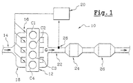
- FIG. 1 shows a treatment system 10 exhaust gas G of a gasoline combustion engine 12 of a motor vehicle, for the implementation of the method according to the invention.
- the motor 12 is supplied with fresh air by a conduit 14.
- Injectors 16 may be arranged in downstream sections 18 of the intake duct 14, or directly in the combustion chambers of the engine 12, so as to provide the motor 12 the amount of fuel needed to its operation.
- motor 12 having four cylinders C1, C2, C3, C4.
- the invention applies also to engines having a higher number of cylinders or less than four.
- An electronic control unit 20 makes it possible to manage the engine operation 12.
- the electronic unit 20 controls in particular the injectors 16 and the admission of air into the intake duct 14, so introducing into each cylinder C1, C2, C3, C4 a mixture fuel of determined wealth.
- An exhaust line 22 allows the evacuation of gases G the engine 12 from combustion, to the atmosphere.
- a treatment system for purifying gases exhaust G is interposed in line 22. It comprises, respectively arranged from upstream to downstream, a trap hydrocarbons 24 and a trifunctional catalyst 26.
- Means of measurement such as pressure sensors and temperature sensors (not shown) can be disposed on the exhaust line 22, upstream and downstream of the trap 24 and catalyst 26, to provide information useful to the electronic unit 20 for controlling the motor 12.
- An oxygen sensor, or lambda probe 28 is arranged in the exhaust line 22, upstream of the trap 24.
- This probe 28 allows the electronic unit 20 to determine whether the fuel mixture introduced into the cylinders C1, C2, C3, C4 is rich or poor.
- the electronic unit 20 uses the information provided by the probe 28 to regulate the richness of the mixture carburetted fuel introduced into the cylinder in order to maintain lambda air coefficient, which is the ratio of the mass of air admitted and the theoretical need for air for combustion stoichiometric, in a range of values called window Catalytic.
- the catalytic window determines the values of the coefficient lambda air for which the treatment efficiency of the three pollutants such as carbon monoxide (CO), hydrocarbons (HC), and nitrogen oxides (NOx), by the Catalyst 26 is optimal.
- the treatment efficiency of the three pollutants such as carbon monoxide (CO), hydrocarbons (HC), and nitrogen oxides (NOx)
- Trap 24 is intended to store hydrocarbons contained in the exhaust gases G at the output of the engine 12 until trap 24 reaches a certain temperature by design, called re-release temperature Tr.
- re-release temperature Tr is for example about 200 degrees Celsius.
- the trap 24 When the trap 24 reaches the re-release temperature Tr, it starts to release the stored hydrocarbons, so that these are evacuated in the gases flowing in the line exhaust 22 to the catalyst 26, for treatment.
- Catalyst 26 is designed in particular to treat by oxidation hydrocarbons (HC) and carbon monoxide (CO) contained in the exhaust G.
- HC oxidation hydrocarbons
- CO carbon monoxide
- the operation of the catalyst 26 comprises a temperature rise phase P mT up to a determined threshold temperature T 100, beyond which the catalyst 26 is able to effectively treat all, or almost all, of the hydrocarbons. emitted upstream, that is to say that its efficiency of treatment of hydrocarbons is globally one hundred percent.
- the threshold temperature T 100 is for example 400 degrees Celsius.
- the catalyst 26 As long as the catalyst 26 has not reached its threshold temperature T 100 , it is not able to effectively treat all the hydrocarbons contained in the exhaust gas G, so that a significant part of those they are not treated and are released into the atmosphere.
- the catalyst 26 reaches a minimum temperature Tmin determined which corresponds to a minimum efficiency of treatment of carbon monoxide by the catalyst 26.
- This minimum temperature is for example about 150 degrees Celsius.
- the catalyst 26 reaches a so-called priming temperature Ta, which corresponds to a minimum treatment efficiency of the hydrocarbons emitted upstream.
- a temperature is chosen of Ta priming which corresponds to a treatment efficiency of fifty percent.
- This Ta priming temperature is by example of about 300 degrees Celsius.
- the operation of the gas treatment system 10 exhaust G according to the method of the invention is as follows.
- a wealth of Er distribution of said step is carried out during the climb phase P mT temperature of the catalyst 26 to accelerate the temperature rise of the catalyst 26 without accelerating the rise in temperature of the trap 24.
- the wealth distribution step Er consists of producing, of a cylinder C1, C2, C3, C4 to another, differences of wealth between the carburetted mixtures, while maintaining the richness average fuel mixes close to wealth stoichiometric, ie by maintaining this wealth average inside the catalytic window.
- the differences in richness between the carburetted mixtures are products by weighting the fuel injection time Di associated with each cylinder C1, C2, C3, C4 by a coefficient ki determined,
- the unweighted duration Di corresponds to a duration reference injection, ie the injection duration calculated or mapped by the electronic unit to maintain the richness of the associated fuel mixture in the catalytic window, without taking into account the implementation of the distribution step of wealth Er.
- the unit weighted electron respectively the injection duration D1, D2, D3, D4 of each injector associated with a cylinder C1, C2, C3, C4 by the coefficients k1, k2, k3, k4, so as to obtain new injection times corrected D1c, D2c, D3c, D4c.
- Each Dic corrected injection duration corresponds to the reference injection time Di multiplied by the coefficient associate ki.
- the fuel mixture introduced into the C1 cylinder has a richness greater than 1, which causes a increase in the amount of carbon monoxide in the exhaust gas G at the output of the engine 12, and the mixture fuel introduced into each of the cylinders C2, C3, C4 has a less than 1, which causes an increase in the amount of oxygen in the exhaust G at the outlet of the engine 12.
- the wealth distribution stage Er is implementation as soon as the catalyst 26 reaches the temperature minimum Tmin allowing a treatment of minimal effectiveness of the carbon monoxide, so the increase in quantities of carbon monoxide in the exhaust gases G to the motor output 12, due to the wealth distribution step Er, can be treated by the catalyst 26.
- the acceleration of the temperature rise of the catalyst 26 contributes to improving the efficiency of carbon monoxide treatment by the catalyst 26, so that the wealth distribution step Er does not cause a increase in carbon monoxide emissions in the atmosphere, despite an increase in carbon monoxide at the output of the engine (12).
- the wealth distribution step Er is implemented at less until the oil trap 24 reaches its start temperature Ta, so that the temperature reached by the catalyst 26, at the moment Tr of the re-release of the trapped hydrocarbons, which is the maximum, which guarantees maximum efficiency of the treatment of hydrocarbons by catalyst 26.
- the Er wealth allocation step is carried out until the catalyst 26 has reached a temperature T 90 at which it can effectively treat about ninety percent of the hydrocarbons.
- the ten percent of remaining efficiency are achieved quickly and "naturally", ie without any distribution of wealth, thanks to the exothermic reactions produced by the treatment of carbon monoxide emitted during normal operation by the engine 12.
- the diagram in Figure 2 shows schematically a curve fc of temperature rise of the catalyst 26 in function of time, as well as a rising curve temperature of the hydrocarbon trap 24 as a function of time.
- trap 24 reaches its re-release temperature Tr, so that he starts to release hydrocarbons who were trapped.
- the catalyst 26 reaches its temperature Ta, so that its efficiency of treatment of hydrocarbons is at least fifty percent.
- the richness distribution step Er is carried out up to time t4, which corresponds to a temperature T 90 of the catalyst 26 for which the catalyst 26 is able to treat approximately ninety percent of the hydrocarbons released by the trap 24.
- the catalyst 26 reaches its threshold temperature T 100 , so that its hydrocarbon treatment efficiency is maximum and about one hundred percent, which leads to the end of the temperature rise phase P mT .
- the temperature of the catalyst 26 can continue to increase after the threshold temperature T 100 .
- the diagram which is represented in parallel on the Figure 3 illustrates schematically the evolution, over time, Eff efficiency of hydrocarbon treatment by the system treatment of exhaust gases G.
- the invention applies to a gas treatment system exhaust G having a catalyzed hydrocarbon trap, that is to say a processing device grouping the functions of hydrocarbon trap and catalyst.
Landscapes
- Engineering & Computer Science (AREA)
- Chemical & Material Sciences (AREA)
- Combustion & Propulsion (AREA)
- Mechanical Engineering (AREA)
- General Engineering & Computer Science (AREA)
- Exhaust Gas After Treatment (AREA)
- Exhaust Gas Treatment By Means Of Catalyst (AREA)
- Electrical Control Of Air Or Fuel Supplied To Internal-Combustion Engine (AREA)
Abstract
Description
- les écarts de richesse entre les mélanges carburés sont produits en pondérant la durée d'injection du carburant dans chaque cylindre par un coefficient déterminé ;
- l'étape de répartition de richesse est mise en oeuvre dès que le catalyseur atteint une température minimale déterminée qui correspond à une efficacité minimale de traitement du monoxyde de carbone ;
- l'étape de répartition de richesse est mise en oeuvre au moins jusqu'à ce que le piège à hydrocarbures atteigne une température dite d'amorçage, qui correspond à une efficacité minimale de traitement des hydrocarbures émis en amont ;
- l'étape de répartition de richesse est mise en oeuvre jusqu'à ce que le catalyseur atteigne une efficacité de traitement des hydrocarbures sensiblement égale à quatre-vingt-dix pourcents.
- la figure 1 représente schématiquement un système de traitement des gaz d'échappement d'un moteur à combustion pour la mise en oeuvre du procédé selon l'invention ;
- la figure 2 est un diagramme schématique qui illustre, en fonction du temps, la montée en température du catalyseur et du piège à hydrocarbure du système d'échappement de la figure 1, lorsque l'on met en oeuvre le procédé selon l'invention ;
- la figure 3 est un diagramme schématique qui illustre, en fonction du temps, l'efficacité de traitement des hydrocarbures par le système de traitement de la figure 1.
Claims (5)
- Procédé de traitement des gaz d'échappement (G) d'un véhicule automobile comportant un moteur à combustion à essence (12) qui comporte plusieurs cylindres (C1, C2, C3, C4), et une ligne d'échappement (22) qui comporte, respectivement d'amont en aval, un piège à hydrocarbures (24) et un catalyseur (26) du type trifonctionnel, le procédé comportant une phase de montée en température (PmT) du catalyseur (26) jusqu'à une température de seuil déterminée (T100) au-delà de laquelle le catalyseur (26) est en mesure de traiter efficacement la totalité des hydrocarbures émis en amont,
caractérisé en ce qu'il comporte une étape de répartition de richesse (Er) qui est mise en oeuvre pendant la phase de montée en température (PmT) du catalyseur (26) pour accélérer cette montée en température, et qui consiste à produire, d'un cylindre (C1, C2, C3, C4) à l'autre, des écarts de richesse entre les mélanges carburés, tout en maintenant la richesse moyenne des mélanges carburés proche de la richesse stoechiométrique, de manière à augmenter les émissions de monoxyde de carbone et de dioxygène dans les gaz d'échappement (G) du moteur (12), en vue de provoquer des réactions exothermiques dans le catalyseur (26). - Procédé selon la revendication précédente, caractérisé en ce que les écarts de richesse entre les mélanges carburés sont produits en pondérant la durée d'injection (Di) du carburant dans chaque cylindre (C1, C2, C3, C4) par un coefficient (ki) déterminé.
- Procédé selon l'une quelconque des revendications précédentes, caractérisé en ce que l'étape de répartition de richesse (Er) est mise en oeuvre dès que le catalyseur (26) atteint une température minimale (Tmin) déterminée qui correspond à une efficacité minimale de traitement du monoxyde de carbone.
- Procédé selon l'une quelconque des revendications précédentes, caractérisé en ce que l'étape de répartition de richesse (Er) est mise en oeuvre au moins jusqu'à ce que le piège à hydrocarbures (24) atteigne une température dite d'amorçage (Ta), qui correspond à une efficacité minimale de traitement des hydrocarbures émis en amont.
- Procédé selon l'une quelconque des revendications 1 à 4, caractérisé en ce que l'étape de répartition de richesse (Er) est mise en oeuvre jusqu'à ce que le catalyseur (26) atteigne une efficacité de traitement des hydrocarbures sensiblement égale à quatre-vingt-dix pourcents.
Applications Claiming Priority (2)
| Application Number | Priority Date | Filing Date | Title |
|---|---|---|---|
| FR0207621 | 2002-06-20 | ||
| FR0207621A FR2841297B1 (fr) | 2002-06-20 | 2002-06-20 | Procede de traitement des gaz d'echappement d'un moteur a combustion a essence |
Publications (2)
| Publication Number | Publication Date |
|---|---|
| EP1375885A1 true EP1375885A1 (fr) | 2004-01-02 |
| EP1375885B1 EP1375885B1 (fr) | 2007-08-01 |
Family
ID=29717058
Family Applications (1)
| Application Number | Title | Priority Date | Filing Date |
|---|---|---|---|
| EP03291414A Expired - Lifetime EP1375885B1 (fr) | 2002-06-20 | 2003-06-13 | Procédé de traitement des gaz d'échappement d'un moteur à combustion à essence |
Country Status (4)
| Country | Link |
|---|---|
| EP (1) | EP1375885B1 (fr) |
| DE (1) | DE60315220T2 (fr) |
| ES (1) | ES2287426T3 (fr) |
| FR (1) | FR2841297B1 (fr) |
Cited By (1)
| Publication number | Priority date | Publication date | Assignee | Title |
|---|---|---|---|---|
| US7770566B2 (en) * | 2005-11-03 | 2010-08-10 | Renault S.A.S. | Method for controlling an internal combustion engine |
Citations (6)
| Publication number | Priority date | Publication date | Assignee | Title |
|---|---|---|---|---|
| US5517820A (en) * | 1993-03-17 | 1996-05-21 | Hitachi, Ltd. | Exhaust gas purifying apparatus and method for internal combustion engine |
| US5661971A (en) * | 1994-12-02 | 1997-09-02 | Volkswagen Ag | Method for reducing pollutants in the exhaust gas of a multi-cylinder internal combustion engine |
| EP0824182A1 (fr) * | 1996-08-15 | 1998-02-18 | Toyota Jidosha Kabushiki Kaisha | Méthode et dispositif pour purifier les gaz d'échappement d'un moteur à combustion interne |
| US6122910A (en) * | 1998-03-23 | 2000-09-26 | Toyota Jidosha Kabushiki Kaisha | Exhaust gas purifying apparatus for an internal combustion engine |
| US6244043B1 (en) * | 1999-05-19 | 2001-06-12 | Ford Global Technologies, Inc. | Emission control device air/fuel ratio control system |
| WO2001090541A1 (fr) * | 2000-05-24 | 2001-11-29 | Johnson Matthey Public Limited Company | Procede de traitement des gaz d'echappement de moteur a essence |
-
2002
- 2002-06-20 FR FR0207621A patent/FR2841297B1/fr not_active Expired - Lifetime
-
2003
- 2003-06-13 ES ES03291414T patent/ES2287426T3/es not_active Expired - Lifetime
- 2003-06-13 EP EP03291414A patent/EP1375885B1/fr not_active Expired - Lifetime
- 2003-06-13 DE DE60315220T patent/DE60315220T2/de not_active Expired - Lifetime
Patent Citations (6)
| Publication number | Priority date | Publication date | Assignee | Title |
|---|---|---|---|---|
| US5517820A (en) * | 1993-03-17 | 1996-05-21 | Hitachi, Ltd. | Exhaust gas purifying apparatus and method for internal combustion engine |
| US5661971A (en) * | 1994-12-02 | 1997-09-02 | Volkswagen Ag | Method for reducing pollutants in the exhaust gas of a multi-cylinder internal combustion engine |
| EP0824182A1 (fr) * | 1996-08-15 | 1998-02-18 | Toyota Jidosha Kabushiki Kaisha | Méthode et dispositif pour purifier les gaz d'échappement d'un moteur à combustion interne |
| US6122910A (en) * | 1998-03-23 | 2000-09-26 | Toyota Jidosha Kabushiki Kaisha | Exhaust gas purifying apparatus for an internal combustion engine |
| US6244043B1 (en) * | 1999-05-19 | 2001-06-12 | Ford Global Technologies, Inc. | Emission control device air/fuel ratio control system |
| WO2001090541A1 (fr) * | 2000-05-24 | 2001-11-29 | Johnson Matthey Public Limited Company | Procede de traitement des gaz d'echappement de moteur a essence |
Cited By (1)
| Publication number | Priority date | Publication date | Assignee | Title |
|---|---|---|---|---|
| US7770566B2 (en) * | 2005-11-03 | 2010-08-10 | Renault S.A.S. | Method for controlling an internal combustion engine |
Also Published As
| Publication number | Publication date |
|---|---|
| DE60315220D1 (de) | 2007-09-13 |
| ES2287426T3 (es) | 2007-12-16 |
| EP1375885B1 (fr) | 2007-08-01 |
| FR2841297B1 (fr) | 2005-04-08 |
| FR2841297A1 (fr) | 2003-12-26 |
| DE60315220T2 (de) | 2008-04-17 |
Similar Documents
| Publication | Publication Date | Title |
|---|---|---|
| FR2741385A1 (fr) | Procede de mise en oeuvre d'un moteur diesel | |
| FR2790789A1 (fr) | Appareil de commande d'emission pour un moteur a combustion interne | |
| EP3973150B1 (fr) | Système de post-traitement des gaz d'échappement d'une ligne d'échappement d'un moteur à combustion interne à allumage commandé | |
| EP0931923A1 (fr) | Procédé de commande de purge d'un pot catalytique de traitement des gaz d'échappement d'un moteur à combustion interne | |
| WO2001027455A1 (fr) | Procede d'injection de carburant pour un moteur a combustion | |
| US7788901B2 (en) | Apparatus and method for regenerating exhaust treatment devices | |
| FR2818687A1 (fr) | Dispositif de purification des gaz d'echappement et procede pour un moteur a combustion interne | |
| EP1375885B1 (fr) | Procédé de traitement des gaz d'échappement d'un moteur à combustion à essence | |
| FR2921969A1 (fr) | Dispositif de post-traitement des gaz d'echappement dispose dans une ligne d'echappement pour un moteur a combustion diesel | |
| FR2905421A1 (fr) | Procede et appareil de commande pour gerer un moteur diesel. | |
| EP0761962B1 (fr) | Procédé de dépollution de moteur à combustion interne à deux temps et applications associées | |
| EP4311927B1 (fr) | Procédé de contrôle de l'injection de carburant dans un moteur à combustion interne et système associé | |
| JP3496572B2 (ja) | 内燃機関の排気浄化装置 | |
| EP1318289A1 (fr) | Dispositif de post traítement des gaz d'échappement et procédé de regénération du dispositif | |
| FR2721653A1 (fr) | Procédé et dispositif de réduction des émissions de polluants d'un moteur à combustion interne. | |
| EP1106804A1 (fr) | Procédé de commande d'un groupe motopropulseur de véhicules automobile pour augmenter la richesse des gaz d'échappement en phase de régénération d'un piège à oxydes d'azote. | |
| FR3129689A1 (fr) | Gestion du fonctionnement d’un catalyseur d’échappement d’un moteur à combustion interne | |
| EP1170494B1 (fr) | Procédé de régulation de la richesse du mélange carburant/air d'alimentation d'un moteur à combustion | |
| EP1183090B1 (fr) | Méthode d'opération d'un moteur à combustion interne | |
| JP2734907B2 (ja) | 排気ガス浄化装置 | |
| FR2881177A1 (fr) | Procede de desulfuration d'un moteur de vehicule | |
| FR3004754A3 (fr) | Procede d'amorcage d'un catalyseur | |
| EP1703105B1 (fr) | Système d'aide à la régénération d'un piège à NOx intégré dans une ligne d'échappement d'un moteur de véhicule automobile | |
| FR3159986A1 (fr) | Procédé de commande d’un moteur à combustion interne à allumage commandé de type atmosphérique muni d’un catalyseur trois voies | |
| FR2847943A1 (fr) | Procede de regeneration de moyens de purification des gaz d'echappement d'un moteur a combustion interne et dispositif de commande d'injection associe |
Legal Events
| Date | Code | Title | Description |
|---|---|---|---|
| PUAI | Public reference made under article 153(3) epc to a published international application that has entered the european phase |
Free format text: ORIGINAL CODE: 0009012 |
|
| AK | Designated contracting states |
Kind code of ref document: A1 Designated state(s): AT BE BG CH CY CZ DE DK EE ES FI FR GB GR HU IE IT LI LU MC NL PT RO SE SI SK TR |
|
| AX | Request for extension of the european patent |
Extension state: AL LT LV MK |
|
| 17P | Request for examination filed |
Effective date: 20040525 |
|
| AKX | Designation fees paid |
Designated state(s): BE DE ES GB IT |
|
| GRAP | Despatch of communication of intention to grant a patent |
Free format text: ORIGINAL CODE: EPIDOSNIGR1 |
|
| GRAS | Grant fee paid |
Free format text: ORIGINAL CODE: EPIDOSNIGR3 |
|
| GRAA | (expected) grant |
Free format text: ORIGINAL CODE: 0009210 |
|
| AK | Designated contracting states |
Kind code of ref document: B1 Designated state(s): BE DE ES GB IT |
|
| REG | Reference to a national code |
Ref country code: GB Ref legal event code: FG4D Free format text: NOT ENGLISH |
|
| REF | Corresponds to: |
Ref document number: 60315220 Country of ref document: DE Date of ref document: 20070913 Kind code of ref document: P |
|
| GBT | Gb: translation of ep patent filed (gb section 77(6)(a)/1977) |
Effective date: 20071004 |
|
| REG | Reference to a national code |
Ref country code: ES Ref legal event code: FG2A Ref document number: 2287426 Country of ref document: ES Kind code of ref document: T3 |
|
| PLBE | No opposition filed within time limit |
Free format text: ORIGINAL CODE: 0009261 |
|
| STAA | Information on the status of an ep patent application or granted ep patent |
Free format text: STATUS: NO OPPOSITION FILED WITHIN TIME LIMIT |
|
| 26N | No opposition filed |
Effective date: 20080506 |
|
| BERE | Be: lapsed |
Owner name: RENAULT S.A.S. Effective date: 20080630 |
|
| PG25 | Lapsed in a contracting state [announced via postgrant information from national office to epo] |
Ref country code: BE Free format text: LAPSE BECAUSE OF NON-PAYMENT OF DUE FEES Effective date: 20080630 |
|
| PGFP | Annual fee paid to national office [announced via postgrant information from national office to epo] |
Ref country code: DE Payment date: 20170621 Year of fee payment: 15 Ref country code: GB Payment date: 20170620 Year of fee payment: 15 |
|
| PGFP | Annual fee paid to national office [announced via postgrant information from national office to epo] |
Ref country code: IT Payment date: 20170622 Year of fee payment: 15 |
|
| PGFP | Annual fee paid to national office [announced via postgrant information from national office to epo] |
Ref country code: ES Payment date: 20170724 Year of fee payment: 15 |
|
| REG | Reference to a national code |
Ref country code: DE Ref legal event code: R119 Ref document number: 60315220 Country of ref document: DE |
|
| GBPC | Gb: european patent ceased through non-payment of renewal fee |
Effective date: 20180613 |
|
| PG25 | Lapsed in a contracting state [announced via postgrant information from national office to epo] |
Ref country code: DE Free format text: LAPSE BECAUSE OF NON-PAYMENT OF DUE FEES Effective date: 20190101 Ref country code: IT Free format text: LAPSE BECAUSE OF NON-PAYMENT OF DUE FEES Effective date: 20180613 Ref country code: GB Free format text: LAPSE BECAUSE OF NON-PAYMENT OF DUE FEES Effective date: 20180613 |
|
| REG | Reference to a national code |
Ref country code: ES Ref legal event code: FD2A Effective date: 20190916 |
|
| PG25 | Lapsed in a contracting state [announced via postgrant information from national office to epo] |
Ref country code: ES Free format text: LAPSE BECAUSE OF NON-PAYMENT OF DUE FEES Effective date: 20180614 |