EP1375879A1 - Controller of internal combustion engine - Google Patents
Controller of internal combustion engine Download PDFInfo
- Publication number
- EP1375879A1 EP1375879A1 EP01917813A EP01917813A EP1375879A1 EP 1375879 A1 EP1375879 A1 EP 1375879A1 EP 01917813 A EP01917813 A EP 01917813A EP 01917813 A EP01917813 A EP 01917813A EP 1375879 A1 EP1375879 A1 EP 1375879A1
- Authority
- EP
- European Patent Office
- Prior art keywords
- throttle opening
- target
- air flow
- flow rate
- target throttle
- Prior art date
- Legal status (The legal status is an assumption and is not a legal conclusion. Google has not performed a legal analysis and makes no representation as to the accuracy of the status listed.)
- Withdrawn
Links
Images


Classifications
-
- F—MECHANICAL ENGINEERING; LIGHTING; HEATING; WEAPONS; BLASTING
- F02—COMBUSTION ENGINES; HOT-GAS OR COMBUSTION-PRODUCT ENGINE PLANTS
- F02D—CONTROLLING COMBUSTION ENGINES
- F02D41/00—Electrical control of supply of combustible mixture or its constituents
- F02D41/02—Circuit arrangements for generating control signals
- F02D41/18—Circuit arrangements for generating control signals by measuring intake air flow
-
- F—MECHANICAL ENGINEERING; LIGHTING; HEATING; WEAPONS; BLASTING
- F02—COMBUSTION ENGINES; HOT-GAS OR COMBUSTION-PRODUCT ENGINE PLANTS
- F02D—CONTROLLING COMBUSTION ENGINES
- F02D11/00—Arrangements for, or adaptations to, non-automatic engine control initiation means, e.g. operator initiated
- F02D11/06—Arrangements for, or adaptations to, non-automatic engine control initiation means, e.g. operator initiated characterised by non-mechanical control linkages, e.g. fluid control linkages or by control linkages with power drive or assistance
- F02D11/10—Arrangements for, or adaptations to, non-automatic engine control initiation means, e.g. operator initiated characterised by non-mechanical control linkages, e.g. fluid control linkages or by control linkages with power drive or assistance of the electric type
- F02D11/105—Arrangements for, or adaptations to, non-automatic engine control initiation means, e.g. operator initiated characterised by non-mechanical control linkages, e.g. fluid control linkages or by control linkages with power drive or assistance of the electric type characterised by the function converting demand to actuation, e.g. a map indicating relations between an accelerator pedal position and throttle valve opening or target engine torque
-
- F—MECHANICAL ENGINEERING; LIGHTING; HEATING; WEAPONS; BLASTING
- F02—COMBUSTION ENGINES; HOT-GAS OR COMBUSTION-PRODUCT ENGINE PLANTS
- F02D—CONTROLLING COMBUSTION ENGINES
- F02D41/00—Electrical control of supply of combustible mixture or its constituents
- F02D41/0002—Controlling intake air
-
- F—MECHANICAL ENGINEERING; LIGHTING; HEATING; WEAPONS; BLASTING
- F02—COMBUSTION ENGINES; HOT-GAS OR COMBUSTION-PRODUCT ENGINE PLANTS
- F02D—CONTROLLING COMBUSTION ENGINES
- F02D41/00—Electrical control of supply of combustible mixture or its constituents
- F02D41/02—Circuit arrangements for generating control signals
- F02D41/14—Introducing closed-loop corrections
- F02D41/1401—Introducing closed-loop corrections characterised by the control or regulation method
-
- F—MECHANICAL ENGINEERING; LIGHTING; HEATING; WEAPONS; BLASTING
- F02—COMBUSTION ENGINES; HOT-GAS OR COMBUSTION-PRODUCT ENGINE PLANTS
- F02D—CONTROLLING COMBUSTION ENGINES
- F02D11/00—Arrangements for, or adaptations to, non-automatic engine control initiation means, e.g. operator initiated
- F02D11/06—Arrangements for, or adaptations to, non-automatic engine control initiation means, e.g. operator initiated characterised by non-mechanical control linkages, e.g. fluid control linkages or by control linkages with power drive or assistance
- F02D11/10—Arrangements for, or adaptations to, non-automatic engine control initiation means, e.g. operator initiated characterised by non-mechanical control linkages, e.g. fluid control linkages or by control linkages with power drive or assistance of the electric type
- F02D2011/101—Arrangements for, or adaptations to, non-automatic engine control initiation means, e.g. operator initiated characterised by non-mechanical control linkages, e.g. fluid control linkages or by control linkages with power drive or assistance of the electric type characterised by the means for actuating the throttles
- F02D2011/102—Arrangements for, or adaptations to, non-automatic engine control initiation means, e.g. operator initiated characterised by non-mechanical control linkages, e.g. fluid control linkages or by control linkages with power drive or assistance of the electric type characterised by the means for actuating the throttles at least one throttle being moved only by an electric actuator
-
- F—MECHANICAL ENGINEERING; LIGHTING; HEATING; WEAPONS; BLASTING
- F02—COMBUSTION ENGINES; HOT-GAS OR COMBUSTION-PRODUCT ENGINE PLANTS
- F02D—CONTROLLING COMBUSTION ENGINES
- F02D41/00—Electrical control of supply of combustible mixture or its constituents
- F02D41/0002—Controlling intake air
- F02D2041/0017—Controlling intake air by simultaneous control of throttle and exhaust gas recirculation
-
- F—MECHANICAL ENGINEERING; LIGHTING; HEATING; WEAPONS; BLASTING
- F02—COMBUSTION ENGINES; HOT-GAS OR COMBUSTION-PRODUCT ENGINE PLANTS
- F02D—CONTROLLING COMBUSTION ENGINES
- F02D41/00—Electrical control of supply of combustible mixture or its constituents
- F02D41/02—Circuit arrangements for generating control signals
- F02D41/14—Introducing closed-loop corrections
- F02D41/1401—Introducing closed-loop corrections characterised by the control or regulation method
- F02D2041/141—Introducing closed-loop corrections characterised by the control or regulation method using a feed-forward control element
-
- F—MECHANICAL ENGINEERING; LIGHTING; HEATING; WEAPONS; BLASTING
- F02—COMBUSTION ENGINES; HOT-GAS OR COMBUSTION-PRODUCT ENGINE PLANTS
- F02D—CONTROLLING COMBUSTION ENGINES
- F02D41/00—Electrical control of supply of combustible mixture or its constituents
- F02D41/02—Circuit arrangements for generating control signals
- F02D41/14—Introducing closed-loop corrections
- F02D41/1401—Introducing closed-loop corrections characterised by the control or regulation method
- F02D2041/1433—Introducing closed-loop corrections characterised by the control or regulation method using a model or simulation of the system
- F02D2041/1434—Inverse model
-
- F—MECHANICAL ENGINEERING; LIGHTING; HEATING; WEAPONS; BLASTING
- F02—COMBUSTION ENGINES; HOT-GAS OR COMBUSTION-PRODUCT ENGINE PLANTS
- F02D—CONTROLLING COMBUSTION ENGINES
- F02D2250/00—Engine control related to specific problems or objectives
- F02D2250/18—Control of the engine output torque
-
- F—MECHANICAL ENGINEERING; LIGHTING; HEATING; WEAPONS; BLASTING
- F02—COMBUSTION ENGINES; HOT-GAS OR COMBUSTION-PRODUCT ENGINE PLANTS
- F02D—CONTROLLING COMBUSTION ENGINES
- F02D41/00—Electrical control of supply of combustible mixture or its constituents
- F02D41/22—Safety or indicating devices for abnormal conditions
- F02D41/222—Safety or indicating devices for abnormal conditions relating to the failure of sensors or parameter detection devices
-
- Y—GENERAL TAGGING OF NEW TECHNOLOGICAL DEVELOPMENTS; GENERAL TAGGING OF CROSS-SECTIONAL TECHNOLOGIES SPANNING OVER SEVERAL SECTIONS OF THE IPC; TECHNICAL SUBJECTS COVERED BY FORMER USPC CROSS-REFERENCE ART COLLECTIONS [XRACs] AND DIGESTS
- Y02—TECHNOLOGIES OR APPLICATIONS FOR MITIGATION OR ADAPTATION AGAINST CLIMATE CHANGE
- Y02T—CLIMATE CHANGE MITIGATION TECHNOLOGIES RELATED TO TRANSPORTATION
- Y02T10/00—Road transport of goods or passengers
- Y02T10/10—Internal combustion engine [ICE] based vehicles
- Y02T10/40—Engine management systems
Definitions
- the present invention relates to internal combustion engine controllers, and more particularly to an internal combustion engine controller for accurately adjusting the air flow rate by controlling the air flow rate with an electronic control valve.
- an in-cylinder fuel injection internal combustion engine which is a lean-burn internal combustion engine, injects fuel directly into a cylinder to stratify an air-fuel mixture, thereby making it possible to achieve combustion at an air-fuel ratio of higher than 40 and reduce the pump loss.
- the air flow rate is not proportional to the torque. Therefore, the lean-burn in-cylinder fuel injection internal combustion engine system generally uses an electronic throttle for electronically controlling the air flow rate unlike a conventional internal combustion engine system.
- torque-on-demand control is required to provide torque desired by the driver at a wide-range air-fuel ratio.
- Two types of torque-on-demand control are an air-based type and a fuel-based type.
- a target torque computation section and a target air-fuel ratio computation section determine a target torque and target air-fuel ratio, respectively, as shown in FIG. 27.
- a target air flow rate computation section for providing the target torque and target air-fuel ratio computes a target air flow rate.
- An electronic throttle controls the air flow rate.
- An air flow rate sensor detects an actual air flow rate.
- a fuel injection quantity computation section determines the quantity of fuel injection from the actual air flow rate and target air-fuel ratio.
- a target torque computation section determines a target torque as shown in FIG. 28.
- a fuel injection quantity computation section determines the quantity of fuel injection for providing the target torque.
- a target air computation section computes a target air flow rate from the fuel injection quantity and target air-fuel ratio.
- An electronic throttle controls the air flow rate.
- fuel-based torque-on-demand control can be exercised to provide feedback control over the air flow rate in accordance with a value output by an air flow sensor.
- Fuel-based torque-on-demand control described above uses an electronic throttle to exercise air flow rate control after fuel injection quantity determination.
- a transmission characteristic exists between the electronic throttle and cylinder. More specifically, a transient phenomenon occurs because it generally takes tens to hundreds of milliseconds for the air flow rate controlled near the electronic throttle to arrive in a cylinder as shown in FIG. 29.
- fuel injection directly occurs within a cylinder. Therefore, the transmission characteristic of the fuel injection side is smaller than that of the air side because time is merely wasted by intermittent combustion.
- the exhaust pipe for an internal combustion engine is usually provided with a three-way catalyst or a catalyst having a three-way catalytic function as an exhaust gas emission purification system.
- the three-way catalyst efficiently purifies carbon hydride (HC), carbon monoxide (CO), which are reducers, and nitrogen oxide (NOx), which is an oxidant, only in the neighborhood of a theoretical air-fuel ratio. From the viewpoint of exhaust gas emission reduction, it is desirable that the air-fuel ratio for an internal combustion engine be adjusted for the theoretical air-fuel ratio.
- the torque of an internal combustion engine is determined almost conclusively by the fuel injection quantity. Therefore, the torque response is determined by the transient characteristic of air flow rate.
- the most important tasks to be accomplished for an internal combustion engine that provides fuel-based torque-on-demand control are to improve the response to air flow rate control and convergence performance, minimize the variations among mass-produced products, and improve the robustness for changes with time.
- JP-A No. 2000-97086 provides control over the air-fuel ratio of an internal combustion engine.
- this technology provides delay compensation to improve the air flow rate response within a cylinder by temporarily permitting the throttle opening to overshoot the degree of throttle opening for achieving the target air flow rate.
- this control method cannot exercise air flow rate control if the air flow sensor is faulty because it computes the target throttle opening in accordance with the deviation between the actual air flow rate and target air flow rate.
- JP-A No. 6-146950 changes the throttle opening by a predetermined amount, if there is any change in the target air-fuel ratio, to eliminate any inadequate feedback response portion of the actual air flow rate with a view toward response improvement.
- this control method does not detect the actual air flow rate, it cannot properly respond, for instance, to air density changes at a high altitude and exhibits low robustness for air flow rate control accuracy in relation to various environmental changes such as throttle control sensor and actuator characteristic variations.
- an object of the present invention to provide an internal combustion engine controller that is capable of exercising high-performance air flow rate control of a fuel-based torque-on-demand control type, in-cylinder fuel injection internal combustion engine while providing improved response and convergence and enhanced robustness.
- an internal combustion engine controller of the present invention basically comprises means for computing a target throttle opening in accordance with operating conditions.
- the means for computing a target throttle opening comprises a first computing means, which determines a target throttle opening by exercising feedback control in accordance with operating conditions including an intake air volume; a second computing means, which determines a target throttle opening by exercising feed-forward control in accordance with the operating conditions; and a third computing means, which determines a target throttle opening in accordance with the respective target throttle opening values determined by the first computing means and second computing means.
- an internal combustion engine controller comprises: a target air flow rate computing means for computing a target air flow rate in accordance with operating conditions; a first computing means for determining a target throttle opening by exercising feedback control in accordance with a difference between the above target air flow rate and an actual air flow rate; a second computing means for determining a target throttle opening by exercising feed-forward control in accordance with the above target air flow rate; and a third computing means for determining a target throttle opening in accordance with the respective target throttle opening values determined by the first computing means and second computing means.
- an internal combustion engine controller for computing a target throttle opening in accordance with operating conditions comprises: a first computing means for determining a target throttle opening by exercising feedback control in accordance with operating conditions including the intake air volume; a second computing means for determining a target throttle opening by exercising feed-forward control in accordance with the operating conditions; a third computing means for determining a target throttle opening in accordance with the target throttle opening values determined by the first computing means and second computing means; and a throttle opening control means for driving a throttle valve in accordance with the target throttle calculated by the third computing means.
- the internal combustion engine controller of the present invention comprises a first throttle opening computing means for computing a throttle opening by exercising feedback control (F/B control) in accordance with the actual air flow rate, target air flow rate, and other operating conditions and a second throttle opening computing means for computing a throttle opening by exercising feed-forward control (F/F control) in accordance with the target air flow rate and other operating conditions. Therefore, the internal combustion engine controller of the present invention can improve the air flow rate calculation response and convergence, reduce the exhaust gas emission, and provides improved torque response without being affected by various environmental changes or sensor, actuator, and other component variations.
- F/B control feedback control
- F/F control feed-forward control
- the internal combustion engine controller of the present invention is particularly suitable for a fuel-based torque-on-demand control type, internal combustion engine. It is basically characterized by comprising a second throttle opening computing means for computing a target throttle opening from a target air flow rate and a first throttle opening computing means for computing a target throttle opening from the deviation between a target air flow rate and actual air flow rate.
- the internal combustion engine controller of the present invention uses the throttle opening control means, which comprises means for controlling the throttle valve in such a manner as to reduce the difference between a directly or indirectly detected actual throttle opening value and a target throttle opening value calculated by the third computing means.
- the internal combustion engine controller of the present invention provides feedback control, which computes the manipulated variable of the throttle in accordance with the difference between the actual throttle opening and a target throttle opening calculated by the third target throttle opening computing means. Therefore, the manipulated variable for throttle drive can be computed from the target throttle opening and actual throttle opening. It means that the manipulated variable for throttle drive indicates a duty ratio that is entered into a drive circuit for controlling a throttle motor drive current. Thus, the manipulated variable for throttle drive can be accurately calculated by means of PID control.
- the internal combustion engine controller of the present invention also provides feed-forward control, which computes the manipulated variable of the throttle in accordance with only the target throttle opening calculated by the third target throttle opening computing means. Therefore, computation control can be exercised with high responsiveness.
- the feed-forward control portion may be a gain only. In such an instance, the manipulated variable for throttle opening control can be computed directly from a target air flow rate without computing a target throttle opening.
- the internal combustion engine controller of the present invention uses the target throttle opening computing means, which comprises a computation permission means for permitting the first target throttle opening computing means to compute a target throttle opening.
- the computation permission means inhibits the first target throttle opening computing means from computing a target throttle opening if the means for detecting the actual air flow rate directly or indirectly is found to be abnormal.
- the third target throttle opening computing means calculates a target throttle opening in accordance with the second target throttle opening so that the actual air flow rate can be adjusted for the target air flow rate.
- the internal combustion engine controller of the present invention comprises a computation permission means for permitting the first target throttle opening computing means to compute a target throttle opening. Therefore, the first target throttle opening computing means can be permitted to compute a target throttle opening when, for instance, the opening of an internal combustion engine accelerator is normal, the air flow sensor function is normal, the throttle is normal, or the elapsed time from startup is as specified. It means that target throttle opening computations can be performed in response to changes in the internal combustion engine environment.
- the means for detecting the air flow rate directly or indirectly is found to be abnormal, it is possible to inhibit the first target throttle opening computing means from computing the first target throttle opening, cause the second target throttle opening computing means to calculate the second target throttle opening as the third target throttle opening, and control the actual air flow rate in accordance with the third target throttle opening. That is, if the means for detecting the air flow rate of the air flow sensor or the like is faulty, the actual air flow rate can be controlled by inhibiting the target throttle opening from being computed by feedback control and using the target throttle opening computed by feed-forward control as the target opening. Therefore, the air flow rate can be preferably controlled even when the air flow sensor or the like is faulty.
- the internal combustion engine controller of the present invention uses the computation permission means to inhibit the first target throttle opening computing means from computing the target throttle opening if the accelerator opening is not smaller than a predetermined value or the second target throttle opening is not smaller than a predetermined value.
- the third target throttle opening computing means computes the target throttle opening in accordance with the second target throttle opening and makes it possible to adjust the actual air flow rate for the target air flow rate.
- the computation permission means inhibits the first target throttle opening computing means from computing the target throttle opening if the difference between the target air flow rate and actual air flow rate is not greater than a predetermined value.
- the third target throttle opening computing means calculates the target throttle opening in accordance with the second target throttle opening and makes it possible to adjust the actual air flow rate to the target air flow rate.
- the internal combustion engine controller of the present invention uses the target throttle opening computing means, which comprises a computation permission means for permitting the second target throttle opening computing means to compute the target throttle opening in accordance with the operating conditions.
- the computation permission means inhibits the second target throttle opening computing means from computing the target throttle opening if a target exhaust gas re-circulation rate is not smaller than a predetermined value.
- the third target throttle opening computing means calculates the target throttle opening in accordance with the first target opening and makes it possible to adjust the actual air flow rate to the target air flow rate.
- the internal combustion engine controller of the present invention comprises a second computation permission means, which permits the second target throttle opening computing means to compute a throttle opening. Therefore, if, for instance, the EGR rate is as specified or the air flow sensor is normal, the second target throttle opening computing means can be permitted to computer the target throttle opening. Thus, it is possible to compute the target throttle opening that is responsive to changes in the internal combustion engine environment.
- the internal combustion engine controller of the present invention uses the target throttle opening computing means to calculate the third target throttle opening from the first target throttle opening, which is computed in accordance with the actual air flow rate even when the relationship between the second target throttle opening and actual air flow rate significantly changes, and makes it possible to adjust the actual air flow rate for the target air flow rate.
- the internal combustion engine controller of the present invention exercises feedback control to provide computation control so as to adjust the actual air flow rate for the target air flow rate and calculate the target throttle opening even when the relationship between the target throttle opening computed by feed-forward control and the actual air flow rate significantly changes due to an air density change, foreign matter inclusion in an intake pipe, or other environmental change. Therefore, the air flow rate can be accurately controlled in response to the above environmental changes.
- the internal combustion engine controller of the present invention uses the target throttle opening computing means, which comprises a target air flow rate correction means for correcting the target air flow rate.
- the first target throttle opening computing means computes the first target throttle opening in accordance with the difference between the target air flow rate calculated by the target air flow rate correction means and the actual air flow rate.
- the target air flow rate correction means represents a response characteristic between the second target throttle opening and actual air flow rate.
- the internal combustion engine controller of the present invention comprises the target air flow rate correction means. Therefore, it can accurately compute a target air flow rate while improving the transmission characteristic by compensating for a time delay involved in intake air flow from the throttle to a cylinder.
- the internal combustion engine controller of the present invention uses the second target throttle opening computing means to compute the second target throttle opening in accordance with the internal combustion engine's rotating speed and the target air flow rate.
- the internal combustion engine controller of the present invention can exercise feed-forward control to compute the second target throttle opening, for instance, from a map depicting the relationship between the internal combustion engine's rotating speed and the target air flow rate.
- the internal combustion engine controller of the present invention comprises means for computing the target exhaust gas re-circulation rate. Further, the second target throttle opening computing means computes the second target throttle opening in accordance with the internal combustion engine's rotating speed, the target air flow rate, and the target exhaust gas re-circulation rate.
- the internal combustion engine controller of the present invention uses the target air flow rate computing means to compute the target air flow rate in accordance with the target air-fuel ratio and target fuel injection quantity.
- the internal combustion engine controller of the present invention can correct the second target throttle opening in accordance with the exhaust gas re-circulation rate when the EGR gas recirculates. More specifically, it can determine the target EGR rate from, for instance, a map depicting the relationship between a target combustion pressure torque and internal combustion engine's rotating speed, determine a throttle opening correction factor from, for instance, a map depicting the relationship between the target EGR rate and target air flow rate, and correct the second target throttle opening.
- the internal combustion engine controller of the present invention comprises a detection means for detecting the internal combustion engine's exhaust gas components directly or indirectly, and a correction amount computing means for computing the correction amount for the target air flow rate in accordance with the exhaust gas components detected by the detection means.
- the internal combustion engine controller of the present invention corrects the target air flow rate with a correction amount (manipulated variable) that is used to compute (by means of air-fuel ratio feedback control) the correction amount for the target air flow rate in accordance with a signal from an A/F sensor or other exhaust gas component detection means. It is therefore possible to calculate a target air flow rate with increased accuracy and compute a target throttle opening.
- a correction amount manipulated variable
- the internal combustion engine controller of the present invention uses the second target throttle opening computing means to compute the second target throttle opening in accordance with an inverse model for the response between an in-cylinder target air flow rate and the throttle.
- the internal combustion engine controller of the present invention uses an in-cylinder air f low rate value, which is detected directly or indirectly, as an actual air flow rate value.
- FIG. 1 illustrates an overall internal combustion engine system that is common to all embodiments to which an internal combustion engine controller according to the present invention is applied.
- An internal combustion engine 20 comprises a multi-cylinder, in-cylinder fuel injection internal combustion engine. Its intake system is such that the air coming from the outside passes through an air cleaner 1, an intake manifold 4, and a collector 5 in order named, and flows into each cylinder 9. The amount of air inflow is regulated by an electronic throttle 3.
- each cylinder 9 is provided with an intake valve 27 and an exhaust valve 28.
- the employed exhaust system is such that an exhaust manifold 10 is connected to each cylinder 10.
- a three-way catalyst 11 is mounted on the exhaust manifold 10.
- an A/F sensor 12 is mounted between each cylinder 9 and the three-way catalyst 11.
- An exhaust gas re-circulation path (EGR path) 18 is furnished to establish communication between the intake manifold 4 and exhaust manifold 10 by bypassing each cylinder 9.
- the EGR path is provided with an EGR valve 19.
- the intake manifold 4 for the intake system is provided with an air flow sensor 2.
- the air flow sensor detects the amount of air inflow.
- a crank angle sensor 15 outputs a signal each time a crankshaft rotates one degree.
- a throttle opening sensor 17, which is mounted on an electronic throttle 3, detects the opening of the electronic throttle 3.
- a water temperature sensor 14 detects a cooling water temperature of the internal combustion engine 20.
- An accelerator opening sensor 13 detects the depression amount of an accelerator 6 for the purpose of detecting a torque demanded by the driver.
- the signals output from the accelerator opening sensor 13, air flow sensor 2, throttle opening sensor 17, crank angle sensor 15, and water temperature sensor 14 are transmitted to a control unit (controller) 50.
- the information about the operating status of the internal combustion engine 20 is derived from the signals output from these sensors to optimally compute major manipulated variables of the internal combustion engine, such as the intake air volume, fuel injection quantity, and ignition timing.
- the fuel injection quantity computed within the control unit 50 is converted to a valve open pulse signal and forwarded to the fuel injection valve 7.
- control unit 50 computes an ignition time as specified. To ensure that ignition takes place at the computed ignition time, the control unit 50 outputs a drive signal to the spark plug 8.
- the intake air delivered from the intake system is regulated by the electronic throttle 3, mixed with a re-circulated exhaust gas that is regulated by the EGR valve 19, and admitted into the cylinder 9 via the intake valve 27.
- the fuel injected from the fuel injection valve 7 into the cylinder (combustion chamber) 9 is mixed with an air inflow from the intake manifold 4 to form an air-fuel mixture.
- the air-fuel mixture is combustively burned by a spark that is generated from the spark plug 8 at the computed ignition time.
- the resulting combustion pressure pushes a piston 29 downward so as to generate motive power for the internal combustion engine 20.
- the exhaust gas generated upon combustion goes into the three-way catalyst 11 via the exhaust manifold 10. All exhaust gas components (HC, CO, and NOx) are then purified in the three-way catalyst 11 and discharged again to the outside.
- the amount of exhaust gas re-circulated to the intake side via an exhaust gas re-circulation pipe 18 is regulated by the EGR valve 19.
- the A/F sensor 12 has a linear output characteristic in relation to the concentration of oxygen contained in the exhaust gas.
- the relationship between the concentration of oxygen in the exhaust gas and the air-fuel ratio is substantially linear. Therefore, the A/F sensor 12, which detects the concentration of oxygen, can determine the air-fuel ratio of the internal combustion engine 20.
- the control unit 50 is configured so as to use the signal from the A/F sensor 12 to calculate the upstream air-fuel ratio of the three-way catalyst 11, and exercise feedback control to successively correct the fuel injection quantity or air flow rate for the purpose of ensuring that the air-fuel ratio of an air-fuel mixture in the cylinder 9 for the internal combustion engine 20 agrees with a target air-fuel ratio.
- FIG. 2 illustrates the internal configuration of the control unit (ECU) 50 for the internal combustion engine 20 shown in FIG. 1.
- the values output from the A/F sensor 12, throttle opening sensor 17, air flow sensor 2, internal combustion engine rotating speed sensor 15, and water temperature sensor 14 enter the ECU 50.
- the output values are then subjected to noise elimination and other signal processes in an input circuit 54, and forwarded to an input/output port 55.
- the value of the input/output port 55 is stored in a RAM 53 and subjected to arithmetic processing by a CPU 51.
- a control program containing the description of arithmetic processing is stored in a ROM 52 beforehand.
- the values representing the amounts of individual actuator operations, which are computed by the control program, are stored in the RAM 53 and then forwarded to the input/output port 55.
- An ON/OFF signal is set as the operation signal for the spark plug 8, which is used for ignition and combustion. This signal is ON when the primary coil in an ignition output circuit 56 is energized and OFF when the same circuit is de-energized. Ignition takes place when the signal status changes from ON to OFF.
- a spark plug signal which is set for the input/output port 55, is amplified to energy adequate for combustion and then supplied to the spark plug 8.
- an ON/OFF signal is set. This signal turns ON to open the valve and turns OFF to close the valve. The signal is amplified to an adequate energy level that is required for operating the fuel injection valve drive circuit 57 to open the fuel injection valve 7, and then forwarded to the fuel injection valve 7.
- a drive signal for opening the electronic throttle 3 to a target degree of opening is delivered to the electronic throttle 3 via an electronic throttle drive circuit 58.
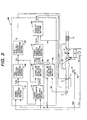
- FIG. 3 is a control block diagram illustrating the overall control operation that the EPU 50 shown in FIG. 2 performs in accordance with a first embodiment. The major portion of a fuel-based, torque-on-demand control is shown in FIG. 3.
- This control comprises a target torque computing section 61, a fuel injection quantity computing section 62, a fuel injection quantity correction section 63, a target equivalence ratio computing section 64, a target air flow rate computing section 65, an actual air flow rate computing section 66, a target throttle opening computing section 67, and a throttle opening control section 68.
- the target torque computing section 61 computes a target torque TgTc from an accelerator opening Apo and an internal computer combustion engine rotating speed Ne.
- the fuel injection quantity computing section 62 operates based on the target torque TgTc to compute a fuel injection quantity TIO that provides the target torque TgTc.
- the fuel injection quantity correction section 63 provides phase compensation so that the fuel injection quantity TIO matches the phase of the air in the cylinder 9, and then computes a corrected fuel injection quantity TI.
- the target equivalence ratio computing section 64 computes a target equivalence ratio TgFbya from the target torque TgTc and internal combustion engine rotating speed Ne.
- TgFbya the ratio between fuel and air is handled in the form of an equivalence ratio.
- the air-fuel ratio may be used as is.
- the target equivalence ratio computing section 64 also chooses between homogeneous combustion and stratified combustion.
- the target air flow rate computing section 65 computes a target air flow rate TgTp from the fuel injection quantity TIO and target equivalence ratio TgFbya. Although this will be described in detail later, the amount of air inflow into a cylinder per cycle is standardized as a value of the target air flow rate TgTp for the sake of convenience.
- the actual air flow rate computing section 66 converts a mass flow rate Qa detected by the air flow sensor 2 into an actual air flow rate Tp, which is of the same dimension as the target air flow rate TgTP and flows into a cylinder per cycle, and then outputs the converted value.
- the target throttle opening computing section 67 computes a target throttle opening TgTvo in accordance with the target air flow rate TgTp and actual air flow rate Tp.
- the throttle opening computing section 68 computes a throttle manipulated variable Tduty from the target throttle opening TgTvo, the actual opening of the electronic throttle 3, and the value Tvo.
- the throttle manipulated variable Tduty represents the duty ratio of a PWM signal that enters a drive circuit 58, which controls a throttle motor drive current.
- FIG. 4 illustrates the target torque computing section 61.
- the value TgTc represents a torque that is equivalent to a target combustion pressure.
- the value TgTa represents a torque required by the accelerator.
- the value TgTl represents an air flow rate that is required for idling speed maintenance.
- an off-idle state provides torque control and an idle state provides output control
- the manipulated variable of an idling control means 61a is a theoretical air-fuel ratio, which is proportional to the output. Gain is provided for use in output-to-torque dimensional conversion.
- the air-conditioner (AC) is ON, the corresponding load is corrected. If any electrical load exists, the corresponding load is corrected.
- a lower-limit value is defined as a BCV portion for assuring an adequate air flow rate for avoiding a reverse oil flow into the cylinder 6.
- An idle feedback control means 61a2 functions during an idle state only in order to correct feed-forward-related error. It is assumed that the controlled variable for the idle feedback control means 61a2 is the rotating speed Ne, and that the manipulated variable is an air flow rate.
- the algorithm for the idle feedback control means 61a2 is not specified herein. However, it may be, for instance, a PID control algorithm.
- An idling judgment section 61b concludes that an idle state exists when the accelerator opening Apo is smaller that specified. It is desirable that the TblTgTa and TblTgTf settings be determined according to actual device data.
- FIG. 5 illustrates the fuel injection quantity computing section 62, which converts a target combustion pressure torque TgTc to a fuel injection quantity TIO for control purposes.
- the fuel injection quantity TIO is proportional to torque because it represents a fuel injection quantity per cylinder per cycle. This proportional relationship is used to convert the target combustion pressure torque TgTc to the fuel injection quantity TIO.
- a gain may be used, but table conversion may be effected in consideration of some possible error. It is desirable that the setting be determined according to actual device data.
- FIG. 6 illustrates the fuel injection quantity correction section 63, which provides correction to adjust the fuel injection quantity TIO for the phase of the air in the cylinder 9.
- the air transmission characteristic between the throttle 3 and cylinder 9 is approximated with wasted time plus first-order lag. It is desirable that the settings for parameter n1, which represents wasted time, and parameter Kair, which corresponds to a time constant for a first-order lag, be determined according to actual device data. Further, parameter n1 and parameter Kair may be varied depending on the operating conditions.
- FIG. 7 illustrates the target equivalence ratio computing section 64, which determines the combustion status and computes the target equivalence ratio.
- the stratified combustion permission flag Fpstratify is 1 to permit stratified combustion if the conditions are satisfied by the water temperature Twn, accelerator opening Apo, and rotating speed Ne.
- the value for letting a stratified combustion target equivalence ratio map Mtgfba_s be referenced by the target combustion pressure torque TgTc and rotating speed Ne is the target equivalence ratio TgFbya.
- TgFbya 0, homogeneous combustion takes place, and the value for letting a homogeneous combustion target equivalence ratio map Mtgfba be referenced by the target combustion pressure TgTc and rotating speed Ne is the target equivalence ratio TgFbya. It is desirable that the settings for the stratified combustion target equivalence ratio map Mtgfba_s and homogeneous combustion target equivalence ratio map Mtgfba be determined according to actual device data.
- FIG. 8 illustrates the target air flow rate computing section 65, which computes the target air flow rate TgTp.
- the target air flow rate TgTp is computed as a standardized value representing the air flow rate that flows into a cylinder per cycle.
- FIG. 9 illustrates the actual air flow rate computing section 66, which computes the actual air flow rate Tp.
- the actual air flow rate Tp is computed as a standardized value representing the air flow rate that flows into a cylinder per cycle.
- the value Qa is an incoming air flow rate that is detected by the air flow sensor 2.
- the value K is determined so that the actual air flow rate Tp provides the fuel injection quantity prevalent at the theoretical air-fuel ratio.
- the value Cyl denotes the number of cylinders for the internal combustion engine 20.
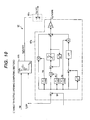
- FIG. 10 illustrates the target throttle opening computing section 67, which determines the target throttle opening TgTVO from the target air flow rate TgTp, actual air flow rate Tp, and rotating speed Ne.
- This control block can be divided into a section 67b (second target throttle opening computing means) for exercising feed-forward control to determine the target throttle opening TgTVOFF from the target air flow rate TgTp and rotating speed Ne and a feedback control section 67a (first target throttle opening computing means) for exercising feedback control to determine the target throttle opening TgTVOFB from the target air flow rate TgTp and actual air flow rate Tp.
- the feed-forward control section 67b determines the target throttle opening TgTVOFF by referencing a map. It is desirable that the map setting be determined according to actual device data.
- the target throttle opening TgTVOFF that is computed by the second section 67b of feed-forward control, and the target throttle opening TgTVOFB that is determined by the first section 67a of feedback control are output to the third control section 67c (third throttle opening computing means).
- the third control section 67c then computes the sum of the target throttle opening TgTVOFF and target throttle opening TgTVOFB and uses the computed sum as the final target throttle opening TgTVO.
- FIG. 11 illustrates the throttle opening control section 68, which computes the throttle drive manipulated variable Tduty from the target throttle opening TgTVO and actual throttle opening Tvo.
- the throttle drive manipulated variable Tduty denotes the duty ratio of a PWM signal that enters a drive circuit 58, which controls a throttle motor drive current. It is assumed that the throttle drive manipulated variable Tduty is determined by means of PID control. Although no details will be given, it is desirable that each PID control gain be tuned with an actual device for optimum results.
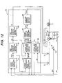
- FIG. 12 is a control block diagram of the second embodiment that illustrates the overall control of the EPU 50 shown in FIG. 2.
- the major portion of a fuel-based, torque-on-demand control is shown in FIG. 12.
- the target torque computing section 61, fuel injection quantity computing section 62, fuel injection quantity correction section 63, target equivalence ratio computing section 64, target air flow rate computing section 65, actual air flow rate computing section 66, and target throttle opening computing section 67 within the control block of the second embodiment are the same as their counterparts described in Sections 1 to 7, respectively, under the first embodiment and will not be described again.
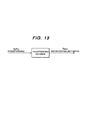
- FIG. 13 illustrates the throttle opening control section 68. As indicated in FIG. 13, feed-forward control is exercised to determine the throttle drive manipulated variable Tduty from the target throttle opening TgTVO only.
- the feed-forward control portion may be a gain only.
- the manipulated variable (Tduty) for throttle opening control is computed directly from a target air flow rate TgTp without computing a target throttle opening.
- the control block of an internal combustion engine controller according to a third embodiment of the present invention will now be described in detail.
- the control block of the third embodiment differs from that of the first embodiment, which is shown in FIG. 3, in that the target air flow rate TgTp for use in feedback control is filtered in relation to a feed-forward control target value in the target throttle opening computing section 67.
- the filter characteristic will be described in detail later. However, it is a response characteristic between the target throttle opening and in-cylinder actual air flow rate that is computed by means of feed-forward control in the target air flow rate computing section 65.
- the purpose is to exercise feedback control to compensate for the steady-state deviation.
- the target torque computing section 61, fuel injection quantity computing section 62, fuel injection quantity correction section 63, target equivalence ratio computing section 64, target air flow rate computing section 65, actual air flow rate computing section 66, and throttle opening control section within the control block of the third embodiment are the same as their counterparts described in Sections 1 to 6 and 8, respectively, under the first embodiment and will not be described again.
- the target air flow rate TgTp for feedback control is a value that is obtained by filtering the target air flow rate TgTp with a filter 67d.
- the specifications for the filter 67c are such that the air transmission characteristic between the throttle 3 and cylinder 9 is approximated with wasted time plus first-order lag. It is desirable that the settings for parameter n2, which represents wasted time, and parameter Kair2, which corresponds to a time constant for a first-order lag, be determined according to actual device data. Further, the parameter n2 and the parameter Kair2 may be varied depending on the operating conditions.
- control block of an internal combustion engine controller according to a fourth embodiment of the present invention will now be described in detail.
- the control block of the fourth embodiment differs from that of the first embodiment, which is shown in FIG. 3, in that the feedback control's computation of target throttle opening TgTVO can be permitted depending on the operating conditions in the target throttle opening computing section 67.
- the target torque computing section 61, fuel injection quantity computing section 62, fuel injection quantity correction section 63, target equivalence ratio computing section 64, target air flow rate computing section 65, actual air flow rate computing section 66, and throttle opening control section within the control block of the fourth embodiment are the same as their counterparts described in Sections 1 to 6 and 8, respectively, under the first embodiment and will not be described again.
- a selector section 67f effects a changeover, as shown in FIG. 16, so that the target throttle opening TgTVOFB is determined by means of feedback control.
- the target throttle opening TgTVOFB is set to 0 without exercising feedback control to perform computations.
- the feedback control computation permission flag FPFB is established when the accelerator opening Apo and the time elapse after internal combustion engine startup Tafst are as specified and the air flow sensor and throttle are both normal.
- the diagnostic check methods for the air flow sensor 2 and throttle 3 are not particularly described herein; however, various practical methods are available.
- control block of an internal combustion engine controller according to a fifth embodiment of the present invention will now be described in detail.
- the control block of the fifth embodiment differs from that of the first embodiment, which is shown in FIG. 3, in that the feed-forward control's computation of target throttle opening TgTPVOFF can be permitted depending on the operating conditions in the target throttle opening computing section 67.
- the target torque computing section 61, fuel injection quantity computing section 62, fuel injection quantity correction section 63, target equivalence ratio computing section 64, target air flow rate computing section 65, actual air flow rate computing section 66, and throttle opening control section within the control block of the fifth embodiment are the same as their counterparts described in Sections 1 to 6 and 8, respectively, under the first embodiment and will not be described again.
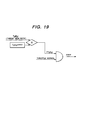
- the target throttle opening TgTVOFF is determined by means of feed-forward control as shown in FIG. 18.
- the feed-forward control computation permission flag FPFF is 0, on the other hand, the target throttle opening TgTVOFF is set to 0 without exercising feed-forward control to perform computations.
- the feed-forward control computation permission flag FPFF is established when the target EGR rate TgEgr is as specified and the air flow sensor is normal. The diagnostic check method for the air flow sensor is not particularly described herein.
- control block of an internal combustion engine controller according to a sixth embodiment of the present invention will now be described in detail.
- the control block of the sixth embodiment differs from that of the first embodiment, which is shown in FIG. 3, in that feed-forward control is exercised in the target throttle opening computing section 67 to compute the target throttle opening TgTVOFF while considering the exhaust gas re-circulation rate.
- the target torque computing section 61, fuel injection quantity computing section 62, fuel injection quantity correction section 63, target equivalence ratio computing section 64, target air flow rate computing section 65, actual air flow rate computing section 66, and throttle opening control section within the control block of the sixth embodiment are the same as their counterparts described in Sections 1 to 6 and 8, respectively, under the first embodiment and will not be described again.
- EgrHOS is a throttle opening correction factor that is used in the event of EGR
- the target throttle opening TgTVOFF0 is determined in the same manner as with the first embodiment.
- a map is referenced in accordance with the target combustion pressure torque TgTc and rotating speed Ne to determine the target EGR rate TgEgr. Further, a map is referenced in accordance with the target EGR rate TgEgr and target air flow rate TgTP to determine the throttle opening correction factor EgrHos. It is desirable that the settings for the maps be determined according to actual device data.
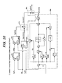
- the control block of an internal combustion engine controller according to a seventh embodiment of the present invention will now be described in detail.
- the control block of the seventh embodiment differs from that of the first embodiment, which is shown in FIG. 3, in that feed-forward control is exercised in the target throttle opening computing section 67 to compute the target throttle opening TgTVOFF in accordance with an inverse model for the response characteristic between the air flow rate in the cylinder 9 and throttle 3. Further, the air flow rate in the cylinder 9 is used as the actual air flow rate Tp for feedback control.
- the target torque computing section 61, fuel injection quantity computing section 62, fuel injection quantity correction section 63, target equivalence ratio computing section 64, target air flow rate computing section 65, and throttle opening control section within the control block of the seventh embodiment are the same as their counterparts described in Sections 1 to 5 and 8, respectively, under the first embodiment and will not be described again.
- the air flow rate Tp1 flowing into a cylinder per cycle is subjected to the air transmission characteristic prevalent between the throttle and cylinder.
- the transmission characteristic is approximated with wasted time plus first-order lag. It is desirable that the settings for parameter n3, which represents wasted time, and parameter Kair3, which corresponds to a time constant for a first-order lag, be determined according to actual device data. Further, the parameter n3 and the parameter Kair3 may be varied depending on the operating conditions.
- an inverse filter (inverse model) 67k is used to determine the target throttle opening TgTVOFF for feed-forward control.
- Detailed specifications for the inverse filter 67k are shown in FIG. 23. It is desirable that the settings for a1, b0, and b1 be determined according to actual device data. It is also conceivable that the settings may be varied depending on the operating conditions.
- FIG. 24 is a control block diagram of the eighth embodiment that illustrates the overall control of the EPU 50 shown in FIG. 2.
- the major portion of a fuel-based, torque-on-demand control is shown in FIG. 24.
- the control block of the eighth embodiment differs from that of the first embodiment, which is shown in FIG. 3, in that an air-fuel ratio feedback control section 69 is added.
- the air-fuel ratio feedback control section 69 provides a manipulated variable Alpha, which is used to correct the target air flow rate TgTP that is computed by the target air flow rate computing section 65.
- the above functionality is added so as to correct the target air flow rate TgTP in accordance with the value output from the A/F sensor 12, which is mounted on the exhaust manifold 10.
- the target torque computing section 61, fuel injection quantity computing section 62, fuel injection quantity correction section 63, target equivalence ratio computing section 64, actual air flow rate computing section 66, target throttle opening computing section 67, and throttle opening control section 68 within the control block of the eighth embodiment are the same as their counterparts described in Sections 1 to 4 and 7 to 9, respectively, under the first embodiment and will not be described again.
- This section exercises feedback control in accordance with the equivalence ratio Rfbya, which is detected by the A/F sensor 12, so that the internal combustion engine's equivalence ratio agrees with the target equivalence ratio TgFbya under arbitrary operating conditions. More specifically, PI control is exercised as indicated in FIG. 25 to compute the air-fuel ratio correction term Alpha from the deviation between the target equivalence ratio TgFbya and the equivalence ratio Rfbya detected by the A/F sensor.
- the target air flow rate TgTp is computed from the target equivalence ratio TgFbya and the equivalence ratio Rfbya detected by the A/F sensor.
- TgTp TIO ⁇ (1/(TgFbya ⁇ Alpha))
- the target throttle opening computed by the second throttle opening computing means and the target throttle opening computed by the first throttle opening computing means are output to the third throttle opening computing means, which computes the sum of the first and second target throttle opening values and uses the computed sum as the final target throttle opening.
- the third throttle opening computing means can alternatively compute the final target throttle opening while considering not only the sum but also the product or other control element.
- an air flow sensor is adopted as means for measuring the air flow rate and used to measure a mass flow rate.
- a pressure sensor for measuring the intake pipe internal pressure may also be used.
- the internal combustion engine controller comprises a first throttle opening computing means, which computes a throttle opening in accordance with a value detected by an air flow sensor, and a second throttle opening computing means, which computes a throttle opening without using a value detected by an air flow sensor. Therefore, when used in a fuel-based torque-on-demand control type internal combustion engine, the internal combustion engine controller according to the present invention can improve air flow rate response and convergence, reduce the exhaust gas emission, and provides improved torque response without being affected by various environmental changes or sensor, actuator, and other component variations.
Landscapes
- Engineering & Computer Science (AREA)
- Chemical & Material Sciences (AREA)
- Combustion & Propulsion (AREA)
- Mechanical Engineering (AREA)
- General Engineering & Computer Science (AREA)
- Electrical Control Of Air Or Fuel Supplied To Internal-Combustion Engine (AREA)
Abstract
Disclosed is an internal combustion engine controller, which is used with a fuel-based torque-on-demand control type, multi-cylinder, direct-injection internal combustion engine to provide an air flow rate control means that excels in response and convergence. This internal combustion engine controller comprises means for computing a target throttle opening from operating conditions. The means for computing a target throttle opening includes: a first computing means for determining a target throttle opening by exercising feedback control in accordance with operating conditions including an intake air flow rate; a second computing means for determining a target throttle opening by exercising feed-forward control in accordance with operating conditions; and a third computing means for determining a target throttle opening in accordance with a target throttle opening value determined by the first computing means and a target throttle opening value determined by the second computing means. <IMAGE>
Description
The present invention relates to internal combustion
engine controllers, and more particularly to an internal
combustion engine controller for accurately adjusting the air
flow rate by controlling the air flow rate with an electronic
control valve.
In recent years, worldwide efforts have been made to
provide increased energy savings. In the field of automotive
technology, the development of a fuel-efficient internal
combustion engine has been required for energy saving
purposes. The most conspicuous internal combustion engine
meeting such a demand is a lean-burn internal combustion
engine. In particular, an in-cylinder fuel injection
internal combustion engine, which is a lean-burn internal
combustion engine, injects fuel directly into a cylinder to
stratify an air-fuel mixture, thereby making it possible to
achieve combustion at an air-fuel ratio of higher than 40 and
reduce the pump loss.
In a lean-burn in-cylinder fuel injection internal
combustion engine system, which is described above, the air
flow rate is not proportional to the torque. Therefore, the
lean-burn in-cylinder fuel injection internal combustion
engine system generally uses an electronic throttle for
electronically controlling the air flow rate unlike a
conventional internal combustion engine system.
For the above lean-burn in-cylinder fuel injection
internal combustion engine system, torque-on-demand control
is required to provide torque desired by the driver at a
wide-range air-fuel ratio. Two types of torque-on-demand
control are an air-based type and a fuel-based type.
If air-based torque-on-demand control is exercised, a
target torque computation section and a target air-fuel ratio
computation section determine a target torque and target air-fuel
ratio, respectively, as shown in FIG. 27. A target air
flow rate computation section for providing the target torque
and target air-fuel ratio computes a target air flow rate.
An electronic throttle controls the air flow rate. An air
flow rate sensor detects an actual air flow rate. A fuel
injection quantity computation section determines the
quantity of fuel injection from the actual air flow rate and
target air-fuel ratio.
If, on the other hand, fuel-based torque-on-demand
control is exercised, a target torque computation section
determines a target torque as shown in FIG. 28. A fuel
injection quantity computation section then determines the
quantity of fuel injection for providing the target torque.
A target air computation section computes a target air flow
rate from the fuel injection quantity and target air-fuel
ratio. An electronic throttle controls the air flow rate.
Further, fuel-based torque-on-demand control can be exercised
to provide feedback control over the air flow rate in
accordance with a value output by an air flow sensor.
Fuel-based torque-on-demand control described above
uses an electronic throttle to exercise air flow rate control
after fuel injection quantity determination. However, a
transmission characteristic exists between the electronic
throttle and cylinder. More specifically, a transient
phenomenon occurs because it generally takes tens to hundreds
of milliseconds for the air flow rate controlled near the
electronic throttle to arrive in a cylinder as shown in FIG.
29. In an in-cylinder fuel injection internal combustion
engine, on the other hand, fuel injection directly occurs
within a cylinder. Therefore, the transmission
characteristic of the fuel injection side is smaller than
that of the air side because time is merely wasted by
intermittent combustion.
Meanwhile, the exhaust pipe for an internal
combustion engine is usually provided with a three-way
catalyst or a catalyst having a three-way catalytic function
as an exhaust gas emission purification system. As shown in
FIG. 30, the three-way catalyst efficiently purifies carbon
hydride (HC), carbon monoxide (CO), which are reducers, and
nitrogen oxide (NOx), which is an oxidant, only in the
neighborhood of a theoretical air-fuel ratio. From the
viewpoint of exhaust gas emission reduction, it is desirable
that the air-fuel ratio for an internal combustion engine be
adjusted for the theoretical air-fuel ratio.
As regards a lean air-fuel ratio, there is a
correlation between the air fuel ratio and internal
combustion engine combustion stability as shown in FIG. 31.
It is therefore necessary to control the air fuel ratio for
the purpose of providing combustion stability of an internal
combustion engine. Thus, when an air flow rate transient
phenomenon in a cylinder is considered, the fuel injection
quantity needs to be controlled from the viewpoint of exhaust
gas emission reduction for theoretical air-fuel ratio or from
the viewpoint of internal combustion engine combustion
stability for lean air-fuel ratio.
Further, the torque of an internal combustion engine
is determined almost conclusively by the fuel injection
quantity. Therefore, the torque response is determined by
the transient characteristic of air flow rate. As is obvious
from the above description, the most important tasks to be
accomplished for an internal combustion engine that provides
fuel-based torque-on-demand control are to improve the
response to air flow rate control and convergence performance,
minimize the variations among mass-produced products, and
improve the robustness for changes with time.
A technology disclosed by JP-A No. 2000-97086
provides control over the air-fuel ratio of an internal
combustion engine. When the target air flow rate changes,
this technology provides delay compensation to improve the
air flow rate response within a cylinder by temporarily
permitting the throttle opening to overshoot the degree of
throttle opening for achieving the target air flow rate.
However, this control method cannot exercise air flow rate
control if the air flow sensor is faulty because it computes
the target throttle opening in accordance with the deviation
between the actual air flow rate and target air flow rate.
Another technology disclosed by JP-A No. 6-146950
changes the throttle opening by a predetermined amount, if
there is any change in the target air-fuel ratio, to
eliminate any inadequate feedback response portion of the
actual air flow rate with a view toward response improvement.
However, since this control method does not detect the actual
air flow rate, it cannot properly respond, for instance, to
air density changes at a high altitude and exhibits low
robustness for air flow rate control accuracy in relation to
various environmental changes such as throttle control sensor
and actuator characteristic variations.
In consideration of the problems described above, it
is an object of the present invention to provide an internal
combustion engine controller that is capable of exercising
high-performance air flow rate control of a fuel-based
torque-on-demand control type, in-cylinder fuel injection
internal combustion engine while providing improved response
and convergence and enhanced robustness.
To achieve the above object, an internal combustion
engine controller of the present invention basically
comprises means for computing a target throttle opening in
accordance with operating conditions. The means for
computing a target throttle opening comprises a first
computing means, which determines a target throttle opening
by exercising feedback control in accordance with operating
conditions including an intake air volume; a second computing
means, which determines a target throttle opening by
exercising feed-forward control in accordance with the
operating conditions; and a third computing means, which
determines a target throttle opening in accordance with the
respective target throttle opening values determined by the
first computing means and second computing means.
In another aspect of the present invention, an
internal combustion engine controller comprises: a target air
flow rate computing means for computing a target air flow
rate in accordance with operating conditions; a first
computing means for determining a target throttle opening by
exercising feedback control in accordance with a difference
between the above target air flow rate and an actual air flow
rate; a second computing means for determining a target
throttle opening by exercising feed-forward control in
accordance with the above target air flow rate; and a third
computing means for determining a target throttle opening in
accordance with the respective target throttle opening values
determined by the first computing means and second computing
means.
In still another aspect of the present invention, an
internal combustion engine controller for computing a target
throttle opening in accordance with operating conditions
comprises: a first computing means for determining a target
throttle opening by exercising feedback control in accordance
with operating conditions including the intake air volume; a
second computing means for determining a target throttle
opening by exercising feed-forward control in accordance with
the operating conditions; a third computing means for
determining a target throttle opening in accordance with the
target throttle opening values determined by the first
computing means and second computing means; and a throttle
opening control means for driving a throttle valve in
accordance with the target throttle calculated by the third
computing means.
As indicated by the configuration described above,
the internal combustion engine controller of the present
invention comprises a first throttle opening computing means
for computing a throttle opening by exercising feedback
control (F/B control) in accordance with the actual air flow
rate, target air flow rate, and other operating conditions
and a second throttle opening computing means for computing a
throttle opening by exercising feed-forward control (F/F
control) in accordance with the target air flow rate and
other operating conditions. Therefore, the internal
combustion engine controller of the present invention can
improve the air flow rate calculation response and
convergence, reduce the exhaust gas emission, and provides
improved torque response without being affected by various
environmental changes or sensor, actuator, and other
component variations.
In other words, the internal combustion engine
controller of the present invention is particularly suitable
for a fuel-based torque-on-demand control type, internal
combustion engine. It is basically characterized by
comprising a second throttle opening computing means for
computing a target throttle opening from a target air flow
rate and a first throttle opening computing means for
computing a target throttle opening from the deviation
between a target air flow rate and actual air flow rate.
Common feedback control computes a manipulated
variable in accordance with the resulting controlled variable.
It is therefore said that the response of feedback control is
theoretically inferior to that of feed-forward control. On
the other hand, it is said that feed-forward control excels
in response but exhibits low robustness against disturbance.
The disadvantages of these two control functions are offset
by the internal combustion engine controller of the present
invention. Concisely, the internal combustion engine
controller of the present invention provides a target
throttle opening computing section that is capable of
exercising feed-forward control, which is highly responsive,
and feedback control, which is robust against disturbance.
Consequently, the internal combustion engine controller of
the present invention provides not only improved response but
also enhanced robustness against disturbance particularly in
air flow rate control over a fuel-based torque-on-demand
control type, internal combustion engine.
To achieve another object, the internal combustion
engine controller of the present invention uses the throttle
opening control means, which comprises means for controlling
the throttle valve in such a manner as to reduce the
difference between a directly or indirectly detected actual
throttle opening value and a target throttle opening value
calculated by the third computing means.
As indicated by the configuration described above,
the internal combustion engine controller of the present
invention provides feedback control, which computes the
manipulated variable of the throttle in accordance with the
difference between the actual throttle opening and a target
throttle opening calculated by the third target throttle
opening computing means. Therefore, the manipulated variable
for throttle drive can be computed from the target throttle
opening and actual throttle opening. It means that the
manipulated variable for throttle drive indicates a duty
ratio that is entered into a drive circuit for controlling a
throttle motor drive current. Thus, the manipulated variable
for throttle drive can be accurately calculated by means of
PID control.
In addition to feedback control, the internal
combustion engine controller of the present invention also
provides feed-forward control, which computes the manipulated
variable of the throttle in accordance with only the target
throttle opening calculated by the third target throttle
opening computing means. Therefore, computation control can
be exercised with high responsiveness. The feed-forward
control portion may be a gain only. In such an instance, the
manipulated variable for throttle opening control can be
computed directly from a target air flow rate without
computing a target throttle opening.
To achieve another object, the internal combustion
engine controller of the present invention uses the target
throttle opening computing means, which comprises a
computation permission means for permitting the first target
throttle opening computing means to compute a target throttle
opening. The computation permission means inhibits the first
target throttle opening computing means from computing a
target throttle opening if the means for detecting the actual
air flow rate directly or indirectly is found to be abnormal.
The third target throttle opening computing means calculates
a target throttle opening in accordance with the second
target throttle opening so that the actual air flow rate can
be adjusted for the target air flow rate.
As indicated in the configuration described above,
the internal combustion engine controller of the present
invention comprises a computation permission means for
permitting the first target throttle opening computing means
to compute a target throttle opening. Therefore, the first
target throttle opening computing means can be permitted to
compute a target throttle opening when, for instance, the
opening of an internal combustion engine accelerator is
normal, the air flow sensor function is normal, the throttle
is normal, or the elapsed time from startup is as specified.
It means that target throttle opening computations can be
performed in response to changes in the internal combustion
engine environment.
Even when the means for detecting the air flow rate
directly or indirectly is found to be abnormal, it is
possible to inhibit the first target throttle opening
computing means from computing the first target throttle
opening, cause the second target throttle opening computing
means to calculate the second target throttle opening as the
third target throttle opening, and control the actual air
flow rate in accordance with the third target throttle
opening. That is, if the means for detecting the air flow
rate of the air flow sensor or the like is faulty, the actual
air flow rate can be controlled by inhibiting the target
throttle opening from being computed by feedback control and
using the target throttle opening computed by feed-forward
control as the target opening. Therefore, the air flow rate
can be preferably controlled even when the air flow sensor or
the like is faulty.
To achieve another object, the internal combustion
engine controller of the present invention uses the
computation permission means to inhibit the first target
throttle opening computing means from computing the target
throttle opening if the accelerator opening is not smaller
than a predetermined value or the second target throttle
opening is not smaller than a predetermined value. The third
target throttle opening computing means computes the target
throttle opening in accordance with the second target
throttle opening and makes it possible to adjust the actual
air flow rate for the target air flow rate. The computation
permission means inhibits the first target throttle opening
computing means from computing the target throttle opening if
the difference between the target air flow rate and actual
air flow rate is not greater than a predetermined value. The
third target throttle opening computing means calculates the
target throttle opening in accordance with the second target
throttle opening and makes it possible to adjust the actual
air flow rate to the target air flow rate.
To achieve another object, the internal combustion
engine controller of the present invention uses the target
throttle opening computing means, which comprises a
computation permission means for permitting the second target
throttle opening computing means to compute the target
throttle opening in accordance with the operating conditions.
The computation permission means inhibits the second target
throttle opening computing means from computing the target
throttle opening if a target exhaust gas re-circulation rate
is not smaller than a predetermined value. The third target
throttle opening computing means calculates the target
throttle opening in accordance with the first target opening
and makes it possible to adjust the actual air flow rate to
the target air flow rate.
As indicated in the configuration described above,
the internal combustion engine controller of the present
invention comprises a second computation permission means,
which permits the second target throttle opening computing
means to compute a throttle opening. Therefore, if, for
instance, the EGR rate is as specified or the air flow sensor
is normal, the second target throttle opening computing means
can be permitted to computer the target throttle opening.
Thus, it is possible to compute the target throttle opening
that is responsive to changes in the internal combustion
engine environment.
To achieve another object, the internal combustion
engine controller of the present invention uses the target
throttle opening computing means to calculate the third
target throttle opening from the first target throttle
opening, which is computed in accordance with the actual air
flow rate even when the relationship between the second
target throttle opening and actual air flow rate
significantly changes, and makes it possible to adjust the
actual air flow rate for the target air flow rate.
As indicated in the configuration described above,
the internal combustion engine controller of the present
invention exercises feedback control to provide computation
control so as to adjust the actual air flow rate for the
target air flow rate and calculate the target throttle
opening even when the relationship between the target
throttle opening computed by feed-forward control and the
actual air flow rate significantly changes due to an air
density change, foreign matter inclusion in an intake pipe,
or other environmental change. Therefore, the air flow rate
can be accurately controlled in response to the above
environmental changes.
To achieve another object, the internal combustion
engine controller of the present invention uses the target
throttle opening computing means, which comprises a target
air flow rate correction means for correcting the target air
flow rate. The first target throttle opening computing means
computes the first target throttle opening in accordance with
the difference between the target air flow rate calculated by
the target air flow rate correction means and the actual air
flow rate. The target air flow rate correction means
represents a response characteristic between the second
target throttle opening and actual air flow rate.
As indicated by the configuration described above,
the internal combustion engine controller of the present
invention comprises the target air flow rate correction means.
Therefore, it can accurately compute a target air flow rate
while improving the transmission characteristic by
compensating for a time delay involved in intake air flow
from the throttle to a cylinder.
To achieve another object, the internal combustion
engine controller of the present invention uses the second
target throttle opening computing means to compute the second
target throttle opening in accordance with the internal
combustion engine's rotating speed and the target air flow
rate.
As indicated by the configuration described above,
the internal combustion engine controller of the present
invention can exercise feed-forward control to compute the
second target throttle opening, for instance, from a map
depicting the relationship between the internal combustion
engine's rotating speed and the target air flow rate.
To achieve another object, the internal combustion
engine controller of the present invention comprises means
for computing the target exhaust gas re-circulation rate.
Further, the second target throttle opening computing means
computes the second target throttle opening in accordance
with the internal combustion engine's rotating speed, the
target air flow rate, and the target exhaust gas re-circulation
rate.
To achieve another object, the internal combustion
engine controller of the present invention uses the target
air flow rate computing means to compute the target air flow
rate in accordance with the target air-fuel ratio and target
fuel injection quantity.
As indicated by the configuration described above,
the internal combustion engine controller of the present
invention can correct the second target throttle opening in
accordance with the exhaust gas re-circulation rate when the
EGR gas recirculates. More specifically, it can determine
the target EGR rate from, for instance, a map depicting the
relationship between a target combustion pressure torque and
internal combustion engine's rotating speed, determine a
throttle opening correction factor from, for instance, a map
depicting the relationship between the target EGR rate and
target air flow rate, and correct the second target throttle
opening.
To achieve another object, the internal combustion
engine controller of the present invention comprises a
detection means for detecting the internal combustion
engine's exhaust gas components directly or indirectly, and a
correction amount computing means for computing the
correction amount for the target air flow rate in accordance
with the exhaust gas components detected by the detection
means.
As indicated by the configuration described above,
the internal combustion engine controller of the present
invention corrects the target air flow rate with a correction
amount (manipulated variable) that is used to compute (by
means of air-fuel ratio feedback control) the correction
amount for the target air flow rate in accordance with a
signal from an A/F sensor or other exhaust gas component
detection means. It is therefore possible to calculate a
target air flow rate with increased accuracy and compute a
target throttle opening.
To achieve another object, the internal combustion
engine controller of the present invention uses the second
target throttle opening computing means to compute the second
target throttle opening in accordance with an inverse model
for the response between an in-cylinder target air flow rate
and the throttle.
To achieve still another object, the internal
combustion engine controller of the present invention uses an
in-cylinder air f low rate value, which is detected directly
or indirectly, as an actual air flow rate value.
Embodiments of an internal combustion engine
controller according to the present invention will now be
described in detail with reference to the accompanying
drawings.
FIG. 1 illustrates an overall internal combustion
engine system that is common to all embodiments to which an
internal combustion engine controller according to the
present invention is applied.
An internal combustion engine 20 comprises a multi-cylinder,
in-cylinder fuel injection internal combustion
engine. Its intake system is such that the air coming from
the outside passes through an air cleaner 1, an intake
manifold 4, and a collector 5 in order named, and flows into
each cylinder 9. The amount of air inflow is regulated by an
electronic throttle 3.
A spark plug 8 and a fuel injection valve 7 are
mounted on each cylinder 9. Further, each cylinder 9 is
provided with an intake valve 27 and an exhaust valve 28.
The employed exhaust system is such that an exhaust manifold
10 is connected to each cylinder 10. A three-way catalyst 11
is mounted on the exhaust manifold 10. Further, an A/F
sensor 12 is mounted between each cylinder 9 and the three-way
catalyst 11.
An exhaust gas re-circulation path (EGR path) 18 is
furnished to establish communication between the intake
manifold 4 and exhaust manifold 10 by bypassing each cylinder
9. The EGR path is provided with an EGR valve 19.
The intake manifold 4 for the intake system is
provided with an air flow sensor 2. The air flow sensor
detects the amount of air inflow. A crank angle sensor 15
outputs a signal each time a crankshaft rotates one degree.
A throttle opening sensor 17, which is mounted on an
electronic throttle 3, detects the opening of the electronic
throttle 3. A water temperature sensor 14 detects a cooling
water temperature of the internal combustion engine 20. An
accelerator opening sensor 13 detects the depression amount
of an accelerator 6 for the purpose of detecting a torque
demanded by the driver.
The signals output from the accelerator opening
sensor 13, air flow sensor 2, throttle opening sensor 17,
crank angle sensor 15, and water temperature sensor 14 are
transmitted to a control unit (controller) 50. The
information about the operating status of the internal
combustion engine 20 is derived from the signals output from
these sensors to optimally compute major manipulated
variables of the internal combustion engine, such as the
intake air volume, fuel injection quantity, and ignition
timing. The fuel injection quantity computed within the
control unit 50 is converted to a valve open pulse signal and
forwarded to the fuel injection valve 7.
Further, the control unit 50 computes an ignition
time as specified. To ensure that ignition takes place at
the computed ignition time, the control unit 50 outputs a
drive signal to the spark plug 8. The intake air delivered
from the intake system is regulated by the electronic
throttle 3, mixed with a re-circulated exhaust gas that is
regulated by the EGR valve 19, and admitted into the cylinder
9 via the intake valve 27.
The fuel injected from the fuel injection valve 7
into the cylinder (combustion chamber) 9 is mixed with an air
inflow from the intake manifold 4 to form an air-fuel mixture.
The air-fuel mixture is combustively burned by a spark that
is generated from the spark plug 8 at the computed ignition
time. The resulting combustion pressure pushes a piston 29
downward so as to generate motive power for the internal
combustion engine 20. The exhaust gas generated upon
combustion goes into the three-way catalyst 11 via the
exhaust manifold 10. All exhaust gas components (HC, CO, and
NOx) are then purified in the three-way catalyst 11 and
discharged again to the outside.
The amount of exhaust gas re-circulated to the intake
side via an exhaust gas re-circulation pipe 18 is regulated
by the EGR valve 19. The A/F sensor 12 has a linear output
characteristic in relation to the concentration of oxygen
contained in the exhaust gas. The relationship between the
concentration of oxygen in the exhaust gas and the air-fuel
ratio is substantially linear. Therefore, the A/F sensor 12,
which detects the concentration of oxygen, can determine the
air-fuel ratio of the internal combustion engine 20.
The control unit 50 is configured so as to use the
signal from the A/F sensor 12 to calculate the upstream air-fuel
ratio of the three-way catalyst 11, and exercise
feedback control to successively correct the fuel injection
quantity or air flow rate for the purpose of ensuring that
the air-fuel ratio of an air-fuel mixture in the cylinder 9
for the internal combustion engine 20 agrees with a target
air-fuel ratio.
FIG. 2 illustrates the internal configuration of the
control unit (ECU) 50 for the internal combustion engine 20
shown in FIG. 1. The values output from the A/F sensor 12,
throttle opening sensor 17, air flow sensor 2, internal
combustion engine rotating speed sensor 15, and water
temperature sensor 14 enter the ECU 50. The output values
are then subjected to noise elimination and other signal
processes in an input circuit 54, and forwarded to an
input/output port 55. The value of the input/output port 55
is stored in a RAM 53 and subjected to arithmetic processing
by a CPU 51. A control program containing the description of
arithmetic processing is stored in a ROM 52 beforehand.
The values representing the amounts of individual
actuator operations, which are computed by the control
program, are stored in the RAM 53 and then forwarded to the
input/output port 55. An ON/OFF signal is set as the
operation signal for the spark plug 8, which is used for
ignition and combustion. This signal is ON when the primary
coil in an ignition output circuit 56 is energized and OFF
when the same circuit is de-energized. Ignition takes place
when the signal status changes from ON to OFF. A spark plug
signal, which is set for the input/output port 55, is
amplified to energy adequate for combustion and then supplied
to the spark plug 8. As a drive signal for the fuel
injection valve 7, an ON/OFF signal is set. This signal
turns ON to open the valve and turns OFF to close the valve.
The signal is amplified to an adequate energy level that is
required for operating the fuel injection valve drive circuit
57 to open the fuel injection valve 7, and then forwarded to
the fuel injection valve 7.
A drive signal for opening the electronic throttle 3
to a target degree of opening is delivered to the electronic
throttle 3 via an electronic throttle drive circuit 58.
The configuration common to all embodiments of an
internal combustion engine controller according to the
present invention has been described. From now on,
individual embodiments will be described.
The control program to be written into the ROM 52 of
the EPU 50 will now be described.
FIG. 3 is a control block diagram illustrating the
overall control operation that the EPU 50 shown in FIG. 2
performs in accordance with a first embodiment. The major
portion of a fuel-based, torque-on-demand control is shown in
FIG. 3.
This control comprises a target torque computing
section 61, a fuel injection quantity computing section 62, a
fuel injection quantity correction section 63, a target
equivalence ratio computing section 64, a target air flow
rate computing section 65, an actual air flow rate computing
section 66, a target throttle opening computing section 67,
and a throttle opening control section 68.
The target torque computing section 61 computes a
target torque TgTc from an accelerator opening Apo and an
internal computer combustion engine rotating speed Ne. The
fuel injection quantity computing section 62 operates based
on the target torque TgTc to compute a fuel injection
quantity TIO that provides the target torque TgTc. The fuel
injection quantity correction section 63 provides phase
compensation so that the fuel injection quantity TIO matches
the phase of the air in the cylinder 9, and then computes a
corrected fuel injection quantity TI.
The target equivalence ratio computing section 64
computes a target equivalence ratio TgFbya from the target
torque TgTc and internal combustion engine rotating speed Ne.
For the sake of convenience, the ratio between fuel and air
is handled in the form of an equivalence ratio. It goes
without saying that the air-fuel ratio may be used as is. It
should be noted that the target equivalence ratio computing
section 64 also chooses between homogeneous combustion and
stratified combustion.
The target air flow rate computing section 65
computes a target air flow rate TgTp from the fuel injection
quantity TIO and target equivalence ratio TgFbya. Although
this will be described in detail later, the amount of air
inflow into a cylinder per cycle is standardized as a value
of the target air flow rate TgTp for the sake of convenience.
The actual air flow rate computing section 66 converts a mass
flow rate Qa detected by the air flow sensor 2 into an actual
air flow rate Tp, which is of the same dimension as the
target air flow rate TgTP and flows into a cylinder per cycle,
and then outputs the converted value.
The target throttle opening computing section 67
computes a target throttle opening TgTvo in accordance with
the target air flow rate TgTp and actual air flow rate Tp.
The throttle opening computing section 68 computes a throttle
manipulated variable Tduty from the target throttle opening
TgTvo, the actual opening of the electronic throttle 3, and
the value Tvo. The throttle manipulated variable Tduty
represents the duty ratio of a PWM signal that enters a drive
circuit 58, which controls a throttle motor drive current.
The control computing sections and correction
sections of the first embodiment of the control block
described above will now be described in detail with
reference to FIGS. 4 to 12.
FIG. 4 illustrates the target torque computing
section 61. The value TgTc represents a torque that is
equivalent to a target combustion pressure. The value TgTa
represents a torque required by the accelerator. The value
TgTl represents an air flow rate that is required for idling
speed maintenance.
Since an off-idle state provides torque control and
an idle state provides output control, it is assumed that the
manipulated variable of an idling control means 61a is a
theoretical air-fuel ratio, which is proportional to the
output. Gain is provided for use in output-to-torque
dimensional conversion. Further, when the air-conditioner
(AC) is ON, the corresponding load is corrected. If any
electrical load exists, the corresponding load is corrected.
For the air flow rate required for idling speed maintenance
TgTl, a lower-limit value is defined as a BCV portion for
assuring an adequate air flow rate for avoiding a reverse oil
flow into the cylinder 6.
An idle feedback control means 61a2 functions during
an idle state only in order to correct feed-forward-related
error. It is assumed that the controlled variable for the
idle feedback control means 61a2 is the rotating speed Ne,
and that the manipulated variable is an air flow rate. The
algorithm for the idle feedback control means 61a2 is not
specified herein. However, it may be, for instance, a PID
control algorithm.
An idling judgment section 61b concludes that an idle
state exists when the accelerator opening Apo is smaller that
specified. It is desirable that the TblTgTa and TblTgTf
settings be determined according to actual device data.
FIG. 5 illustrates the fuel injection quantity
computing section 62, which converts a target combustion
pressure torque TgTc to a fuel injection quantity TIO for
control purposes. The fuel injection quantity TIO is
proportional to torque because it represents a fuel injection
quantity per cylinder per cycle. This proportional
relationship is used to convert the target combustion
pressure torque TgTc to the fuel injection quantity TIO. A
gain may be used, but table conversion may be effected in
consideration of some possible error. It is desirable that
the setting be determined according to actual device data.
FIG. 6 illustrates the fuel injection quantity
correction section 63, which provides correction to adjust
the fuel injection quantity TIO for the phase of the air in
the cylinder 9. The air transmission characteristic between
the throttle 3 and cylinder 9 is approximated with wasted
time plus first-order lag. It is desirable that the settings
for parameter n1, which represents wasted time, and parameter
Kair, which corresponds to a time constant for a first-order
lag, be determined according to actual device data. Further,
parameter n1 and parameter Kair may be varied depending on
the operating conditions.
FIG. 7 illustrates the target equivalence ratio
computing section 64, which determines the combustion status
and computes the target equivalence ratio. Fpstratify is a
stratified combustion permission flag. When Fpstratify = 1,
the injection time, ignition time, injection quantity, and
air flow rate are regulated to provide stratified combustion.
Injection time/ignition time determination is not described
herein. The stratified combustion permission flag Fpstratify
is 1 to permit stratified combustion if the conditions are
satisfied by the water temperature Twn, accelerator opening
Apo, and rotating speed Ne. When stratified combustion is
permitted, the value for letting a stratified combustion
target equivalence ratio map Mtgfba_s be referenced by the
target combustion pressure torque TgTc and rotating speed Ne
is the target equivalence ratio TgFbya. When TgFbya = 0,
homogeneous combustion takes place, and the value for letting
a homogeneous combustion target equivalence ratio map Mtgfba
be referenced by the target combustion pressure TgTc and
rotating speed Ne is the target equivalence ratio TgFbya. It
is desirable that the settings for the stratified combustion
target equivalence ratio map Mtgfba_s and homogeneous
combustion target equivalence ratio map Mtgfba be determined
according to actual device data.
FIG. 8 illustrates the target air flow rate computing
section 65, which computes the target air flow rate TgTp.
For the sake of convenience, the target air flow rate TgTp is
computed as a standardized value representing the air flow
rate that flows into a cylinder per cycle. As is obvious
from FIG. 8, the target air flow rate TgTp is calculated from
the fuel injection quantity TIO and target equivalence ratio
TgFbya. The equation used for this calculation is as
follows:
TgTp = TIO × (1/TgFbya)
FIG. 9 illustrates the actual air flow rate computing
section 66, which computes the actual air flow rate Tp. For
the sake of convenience, the actual air flow rate Tp is
computed as a standardized value representing the air flow
rate that flows into a cylinder per cycle. The value Qa is
an incoming air flow rate that is detected by the air flow
sensor 2. The value K is determined so that the actual air
flow rate Tp provides the fuel injection quantity prevalent
at the theoretical air-fuel ratio. The value Cyl denotes the
number of cylinders for the internal combustion engine 20.
FIG. 10 illustrates the target throttle opening
computing section 67, which determines the target throttle
opening TgTVO from the target air flow rate TgTp, actual air
flow rate Tp, and rotating speed Ne. This control block can
be divided into a section 67b (second target throttle opening
computing means) for exercising feed-forward control to
determine the target throttle opening TgTVOFF from the target
air flow rate TgTp and rotating speed Ne and a feedback
control section 67a (first target throttle opening computing
means) for exercising feedback control to determine the
target throttle opening TgTVOFB from the target air flow rate
TgTp and actual air flow rate Tp. It is assumed, as shown in
FIG. 10, that the feed-forward control section 67b determines
the target throttle opening TgTVOFF by referencing a map. It
is desirable that the map setting be determined according to
actual device data.
Feedback control is exercised to provide PID control.
Each gain is given as a magnitude of deviation between the
target air flow rate TgTp and actual air flow rate TpTg.
However, it is desirable that the setting be determined
according to actual device data. For the D portion, an LPF
(low-pass filter) is provided for high-frequency noise
elimination.
The target throttle opening TgTVOFF that is computed
by the second section 67b of feed-forward control, and the
target throttle opening TgTVOFB that is determined by the
first section 67a of feedback control are output to the third
control section 67c (third throttle opening computing means).
The third control section 67c then computes the sum of the
target throttle opening TgTVOFF and target throttle opening
TgTVOFB and uses the computed sum as the final target
throttle opening TgTVO.
FIG. 11 illustrates the throttle opening control
section 68, which computes the throttle drive manipulated
variable Tduty from the target throttle opening TgTVO and
actual throttle opening Tvo. As described earlier, the
throttle drive manipulated variable Tduty denotes the duty
ratio of a PWM signal that enters a drive circuit 58, which
controls a throttle motor drive current. It is assumed that
the throttle drive manipulated variable Tduty is determined
by means of PID control. Although no details will be given,
it is desirable that each PID control gain be tuned with an
actual device for optimum results.
The control block of an internal combustion engine
controller according to a second embodiment of the present
invention will now be described in detail. FIG. 12 is a
control block diagram of the second embodiment that
illustrates the overall control of the EPU 50 shown in FIG. 2.
The major portion of a fuel-based, torque-on-demand control
is shown in FIG. 12.
The target torque computing section 61, fuel
injection quantity computing section 62, fuel injection
quantity correction section 63, target equivalence ratio
computing section 64, target air flow rate computing section
65, actual air flow rate computing section 66, and target
throttle opening computing section 67 within the control
block of the second embodiment are the same as their
counterparts described in Sections 1 to 7, respectively,
under the first embodiment and will not be described again.
FIG. 13 illustrates the throttle opening control
section 68. As indicated in FIG. 13, feed-forward control is
exercised to determine the throttle drive manipulated
variable Tduty from the target throttle opening TgTVO only.
The feed-forward control portion may be a gain only.
In such an instance, however, the manipulated variable
(Tduty) for throttle opening control is computed directly
from a target air flow rate TgTp without computing a target
throttle opening.
The control block of an internal combustion engine
controller according to a third embodiment of the present
invention will now be described in detail. The control block
of the third embodiment differs from that of the first
embodiment, which is shown in FIG. 3, in that the target air
flow rate TgTp for use in feedback control is filtered in
relation to a feed-forward control target value in the target
throttle opening computing section 67. The filter
characteristic will be described in detail later. However,
it is a response characteristic between the target throttle
opening and in-cylinder actual air flow rate that is computed
by means of feed-forward control in the target air flow rate
computing section 65. The purpose is to exercise feedback
control to compensate for the steady-state deviation.
The target torque computing section 61, fuel
injection quantity computing section 62, fuel injection
quantity correction section 63, target equivalence ratio
computing section 64, target air flow rate computing section
65, actual air flow rate computing section 66, and throttle
opening control section within the control block of the third
embodiment are the same as their counterparts described in
Sections 1 to 6 and 8, respectively, under the first
embodiment and will not be described again.
As shown in FIG. 14, the target air flow rate TgTp
for feedback control is a value that is obtained by filtering
the target air flow rate TgTp with a filter 67d. As
indicated in FIG. 15, the specifications for the filter 67c
are such that the air transmission characteristic between the
throttle 3 and cylinder 9 is approximated with wasted time
plus first-order lag. It is desirable that the settings for
parameter n2, which represents wasted time, and parameter
Kair2, which corresponds to a time constant for a first-order
lag, be determined according to actual device data. Further,
the parameter n2 and the parameter Kair2 may be varied
depending on the operating conditions.
The control block of an internal combustion engine
controller according to a fourth embodiment of the present
invention will now be described in detail. The control block
of the fourth embodiment differs from that of the first
embodiment, which is shown in FIG. 3, in that the feedback
control's computation of target throttle opening TgTVO can be
permitted depending on the operating conditions in the target
throttle opening computing section 67.
The target torque computing section 61, fuel
injection quantity computing section 62, fuel injection
quantity correction section 63, target equivalence ratio
computing section 64, target air flow rate computing section
65, actual air flow rate computing section 66, and throttle
opening control section within the control block of the
fourth embodiment are the same as their counterparts
described in Sections 1 to 6 and 8, respectively, under the
first embodiment and will not be described again.
When the feedback control computation permission flag
FPFB is 1 in the feedback control permission judgment section
67e, a selector section 67f effects a changeover, as shown in
FIG. 16, so that the target throttle opening TgTVOFB is
determined by means of feedback control. When the feedback
control computation permission flag FPFB is 0, on the other
hand, the target throttle opening TgTVOFB is set to 0 without
exercising feedback control to perform computations. As
indicated in FIG. 17, the feedback control computation
permission flag FPFB is established when the accelerator
opening Apo and the time elapse after internal combustion
engine startup Tafst are as specified and the air flow sensor
and throttle are both normal. The diagnostic check methods
for the air flow sensor 2 and throttle 3 are not particularly
described herein; however, various practical methods are
available.
The control block of an internal combustion engine
controller according to a fifth embodiment of the present
invention will now be described in detail. The control block
of the fifth embodiment differs from that of the first
embodiment, which is shown in FIG. 3, in that the feed-forward
control's computation of target throttle opening
TgTPVOFF can be permitted depending on the operating
conditions in the target throttle opening computing section
67.
The target torque computing section 61, fuel
injection quantity computing section 62, fuel injection
quantity correction section 63, target equivalence ratio
computing section 64, target air flow rate computing section
65, actual air flow rate computing section 66, and throttle
opening control section within the control block of the fifth
embodiment are the same as their counterparts described in
Sections 1 to 6 and 8, respectively, under the first
embodiment and will not be described again.
When the feed-forward control computation permission
flag FPFB is 1 in the feed-forward control permission
judgment section 67g, the target throttle opening TgTVOFF is
determined by means of feed-forward control as shown in FIG.
18. When the feed-forward control computation permission
flag FPFF is 0, on the other hand, the target throttle
opening TgTVOFF is set to 0 without exercising feed-forward
control to perform computations. As indicated in FIG. 19,
the feed-forward control computation permission flag FPFF is
established when the target EGR rate TgEgr is as specified
and the air flow sensor is normal. The diagnostic check
method for the air flow sensor is not particularly described
herein.
The control block of an internal combustion engine
controller according to a sixth embodiment of the present
invention will now be described in detail. The control block
of the sixth embodiment differs from that of the first
embodiment, which is shown in FIG. 3, in that feed-forward
control is exercised in the target throttle opening computing
section 67 to compute the target throttle opening TgTVOFF
while considering the exhaust gas re-circulation rate.
The target torque computing section 61, fuel
injection quantity computing section 62, fuel injection
quantity correction section 63, target equivalence ratio
computing section 64, target air flow rate computing section
65, actual air flow rate computing section 66, and throttle
opening control section within the control block of the sixth
embodiment are the same as their counterparts described in
Sections 1 to 6 and 8, respectively, under the first
embodiment and will not be described again.
As indicated in FIG. 20, the target throttle opening
TgTVOFF, which is determined by means of feed-forward control,
is calculated according to the following equation:
TgTVOFF = TgTVOFF0 × EgrHos
where EgrHOS is a throttle opening correction factor
that is used in the event of EGR, and the target throttle
opening TgTVOFF0 is determined in the same manner as with the
first embodiment. As indicated in FIG. 20, a map is
referenced in accordance with the target combustion pressure
torque TgTc and rotating speed Ne to determine the target EGR
rate TgEgr. Further, a map is referenced in accordance with
the target EGR rate TgEgr and target air flow rate TgTP to
determine the throttle opening correction factor EgrHos. It
is desirable that the settings for the maps be determined
according to actual device data.
The control block of an internal combustion engine
controller according to a seventh embodiment of the present
invention will now be described in detail. The control block
of the seventh embodiment differs from that of the first
embodiment, which is shown in FIG. 3, in that feed-forward
control is exercised in the target throttle opening computing
section 67 to compute the target throttle opening TgTVOFF in
accordance with an inverse model for the response
characteristic between the air flow rate in the cylinder 9
and throttle 3. Further, the air flow rate in the cylinder 9
is used as the actual air flow rate Tp for feedback control.
The target torque computing section 61, fuel
injection quantity computing section 62, fuel injection
quantity correction section 63, target equivalence ratio
computing section 64, target air flow rate computing section
65, and throttle opening control section within the control
block of the seventh embodiment are the same as their
counterparts described in Sections 1 to 5 and 8, respectively,
under the first embodiment and will not be described again.
As indicated in FIG. 21, the air flow rate Tp1
flowing into a cylinder per cycle is subjected to the air
transmission characteristic prevalent between the throttle
and cylinder. The transmission characteristic is
approximated with wasted time plus first-order lag. It is
desirable that the settings for parameter n3, which
represents wasted time, and parameter Kair3, which
corresponds to a time constant for a first-order lag, be
determined according to actual device data. Further, the
parameter n3 and the parameter Kair3 may be varied depending
on the operating conditions.
As indicated in FIG. 22, an inverse filter (inverse
model) 67k is used to determine the target throttle opening
TgTVOFF for feed-forward control. Detailed specifications
for the inverse filter 67k are shown in FIG. 23. It is
desirable that the settings for a1, b0, and b1 be determined
according to actual device data. It is also conceivable that
the settings may be varied depending on the operating
conditions.
The control block of an internal combustion engine
controller according to an eighth embodiment of the present
invention will now be described in detail. FIG. 24 is a
control block diagram of the eighth embodiment that
illustrates the overall control of the EPU 50 shown in FIG. 2.
The major portion of a fuel-based, torque-on-demand control
is shown in FIG. 24.
The control block of the eighth embodiment differs
from that of the first embodiment, which is shown in FIG. 3,
in that an air-fuel ratio feedback control section 69 is
added. The air-fuel ratio feedback control section 69
provides a manipulated variable Alpha, which is used to
correct the target air flow rate TgTP that is computed by the
target air flow rate computing section 65. The above
functionality is added so as to correct the target air flow
rate TgTP in accordance with the value output from the A/F
sensor 12, which is mounted on the exhaust manifold 10.
The target torque computing section 61, fuel
injection quantity computing section 62, fuel injection
quantity correction section 63, target equivalence ratio
computing section 64, actual air flow rate computing section
66, target throttle opening computing section 67, and
throttle opening control section 68 within the control block
of the eighth embodiment are the same as their counterparts
described in Sections 1 to 4 and 7 to 9, respectively, under
the first embodiment and will not be described again.
This section exercises feedback control in accordance
with the equivalence ratio Rfbya, which is detected by the
A/F sensor 12, so that the internal combustion engine's
equivalence ratio agrees with the target equivalence ratio
TgFbya under arbitrary operating conditions. More
specifically, PI control is exercised as indicated in FIG. 25
to compute the air-fuel ratio correction term Alpha from the
deviation between the target equivalence ratio TgFbya and the
equivalence ratio Rfbya detected by the A/F sensor.
As shown in FIG. 26, the target air flow rate TgTp is
computed from the target equivalence ratio TgFbya and the
equivalence ratio Rfbya detected by the A/F sensor. For
computation, the following equation is used:
TgTp = TIO × (1/(TgFbya × Alpha))
Although the present invention has been described in
detail with reference to the first to eighth embodiments
thereof, it will be readily apparent to those skilled in the
art that the present invention is not limited to those
preferred embodiments, and that various design changes may be
made therein without departing from the spirit and scope of
the appended claims.
In the target throttle opening computing section, for
instance, the target throttle opening computed by the second
throttle opening computing means and the target throttle
opening computed by the first throttle opening computing
means are output to the third throttle opening computing
means, which computes the sum of the first and second target
throttle opening values and uses the computed sum as the
final target throttle opening. However, the third throttle
opening computing means can alternatively compute the final
target throttle opening while considering not only the sum
but also the product or other control element.
In the foregoing embodiments, an air flow sensor is
adopted as means for measuring the air flow rate and used to
measure a mass flow rate. In an alternative embodiment,
however, a pressure sensor for measuring the intake pipe
internal pressure may also be used.
As described above, the internal combustion engine
controller according to the present invention comprises a
first throttle opening computing means, which computes a
throttle opening in accordance with a value detected by an
air flow sensor, and a second throttle opening computing
means, which computes a throttle opening without using a
value detected by an air flow sensor. Therefore, when used
in a fuel-based torque-on-demand control type internal
combustion engine, the internal combustion engine controller
according to the present invention can improve air flow rate
response and convergence, reduce the exhaust gas emission,
and provides improved torque response without being affected
by various environmental changes or sensor, actuator, and
other component variations.
Claims (19)
- An internal combustion engine controller, comprising:wherein the means for computing a target throttle opening comprises:means for computing a target throttle opening from operating conditions;a first computing means for determining a target throttle opening by exercising feedback control in accordance with operating conditions including an intake air flow rate;a second computing means for determining a target throttle opening by exercising feed-forward control in accordance with operating conditions; anda third computing means for determining a target throttle opening in accordance with a target throttle opening value determined by said first computing means and a target throttle opening value determined by said second computing means.
- An internal combustion engine controller, comprising:a target air flow rate computing means for computing a target air flow rate in accordance with operating conditions;a first computing means for determining a target throttle opening by exercising feedback control in accordance with a difference between said target air flow rate and an actual air flow rate;a second computing means for determining a target throttle opening by exercising feed-forward control in accordance with said target air flow rate; anda third computing means for determining a target throttle opening in accordance with a target throttle opening value determined by said first computing means and a target throttle opening value determined by said second computing means.
- An internal combustion engine controller, comprising:wherein the control unit comprises:a control unit for computing a target throttle opening from operating conditions;a first computing means for determining a target throttle opening by exercising feedback control in accordance with operating conditions including an intake air flow rate;a second computing means for determining a target throttle opening by exercising feed-forward control in accordance with operating conditions;a third computing means for determining a target throttle opening in accordance with a target throttle opening value determined by said first computing means and a target throttle opening value determined by said second computing means; anda throttle opening control means for driving a throttle in accordance with a target throttle opening calculated by said third computing means.
- The internal combustion engine controller according to claim 3, wherein said throttle opening control means comprises means for controlling a throttle in such a manner as to reduce a difference between a target throttle opening calculated by said third computing means and a directly or indirectly detected actual throttle opening.
- The internal combustion engine controller according to claim 1, wherein said target throttle opening computing means comprises a computation permission means for permitting said first target throttle opening computing means to compute a target throttle opening.
- The internal combustion engine controller according to claim 5, wherein said computation permission means inhibits said first target throttle opening computing means from computing a target throttle opening if means for detecting an actual air flow rate directly or indirectly is found to be abnormal; and
wherein said third target throttle opening computing means calculates a target throttle opening in accordance with a second target throttle opening and makes it possible to adjust the actual air flow rate for a target air flow rate. - The internal combustion engine controller according to claim 5, wherein said computation permission means inhibits said first target throttle opening computing means from computing a target throttle opening if an accelerator opening is not smaller than a predetermined value or said second target throttle opening is not smaller than a predetermined value; and
wherein said third target throttle opening computing means calculates a target throttle opening in accordance with the second target throttle opening and makes it possible to adjust an actual air flow rate to a target air flow rate. - The internal combustion engine controller according to claim 5, wherein said computation permission means inhibits said first target throttle opening computing means from calculating a target throttle opening if a difference between a target air flow rate and an actual air flow rate is not greater than a predetermined value; and
wherein said third target throttle opening computing means calculates a target throttle opening in accordance with the second target throttle opening and makes it possible to adjust an actual air flow rate to a target air flow rate. - The internal combustion engine controller according to claim 1, wherein said target throttle opening computing means comprises a computation permission means for permitting said second target throttle opening computing means to compute a target throttle opening in accordance with operating conditions.
- The internal combustion engine controller according to claim 9, wherein said computation permission means inhibits said second target throttle opening computing means from computing a target throttle opening if a target exhaust gas re-circulation rate is not lower than a predetermined value; and
wherein said third target throttle opening computing means calculates a target throttle opening in accordance with a first target opening and makes it possible to adjust an actual air flow rate to a target air flow rate. - The internal combustion engine controller according to claim 1, wherein said target throttle opening computing means makes it possible to adjust an actual air flow rate to a target air flow rate by calculating said third target throttle opening from said first target throttle opening, which is computed in accordance with an actual air flow rate, even if a relationship between said second target throttle opening and the actual air flow rate is significantly changed.
- The internal combustion engine controller according to claim 2, wherein said target throttle opening computing means comprises a target air flow rate correction means for correcting said target air flow rate; and
wherein said first target throttle opening computing means computes a first target throttle opening in accordance with a difference between an actual air flow rate and a target air flow rate calculated by said target air flow rate correction means. - The internal combustion engine controller according to claim 12, wherein said target air flow rate correction means represents a response characteristic between said second target throttle opening and an actual air flow rate.
- The internal combustion engine controller according to claim 1, wherein said second target throttle opening computing means computes a second target throttle opening in accordance with a rotating speed of an internal combustion engine and a target air flow rate.
- The internal combustion engine controller according to claim 1, further comprising means for computing a target exhaust gas re-circulation rate;
wherein said second target throttle opening computing means computes a second target throttle opening in accordance with a rotating speed of an internal combustion engine, a target air flow rate, and the target exhaust gas re-circulation rate. - The internal combustion engine controller according to claim 2, wherein said target air flow rate computing means computes said target air flow rate in accordance with a target air-fuel ratio and a target fuel injection quantity.
- The internal combustion engine controller according to claim 2, further comprising:detection means for detecting exhaust gas components of an internal combustion engine directly or indirectly; anda correction amount computing means for computing an amount of correction for said target air flow rate in accordance with the exhaust gas components detected by said detection means.
- The internal combustion engine controller according to claim 1, wherein said second target throttle opening computing means computes a second target throttle opening in accordance with an inverse model for a response between an in-cylinder target air flow rate and a throttle opening.
- The internal combustion engine controller according to claim 1, wherein the actual air flow rate is a value obtained by detecting an in-cylinder air flow rate directly or indirectly.
Applications Claiming Priority (1)
| Application Number | Priority Date | Filing Date | Title |
|---|---|---|---|
| PCT/JP2001/002901 WO2002081888A1 (en) | 2001-04-03 | 2001-04-03 | Controller of internal combustion engine |
Publications (2)
| Publication Number | Publication Date |
|---|---|
| EP1375879A1 true EP1375879A1 (en) | 2004-01-02 |
| EP1375879A4 EP1375879A4 (en) | 2009-09-30 |
Family
ID=11737224
Family Applications (1)
| Application Number | Title | Priority Date | Filing Date |
|---|---|---|---|
| EP01917813A Withdrawn EP1375879A4 (en) | 2001-04-03 | 2001-04-03 | INTERNAL COMBUSTION CONTROL UNIT |
Country Status (4)
| Country | Link |
|---|---|
| US (1) | US7267100B2 (en) |
| EP (1) | EP1375879A4 (en) |
| JP (1) | JP4065784B2 (en) |
| WO (1) | WO2002081888A1 (en) |
Cited By (2)
| Publication number | Priority date | Publication date | Assignee | Title |
|---|---|---|---|---|
| GB2484745A (en) * | 2010-10-18 | 2012-04-25 | Gm Global Tech Operations Inc | A method for feed-forward controlling fuel injection into a cylinder of an internal combustion engine |
| EP2320055A4 (en) * | 2008-08-22 | 2015-08-19 | Chery Automobile Co Ltd | Control method of diesel engine intake vortex |
Families Citing this family (18)
| Publication number | Priority date | Publication date | Assignee | Title |
|---|---|---|---|---|
| EP1310649B1 (en) * | 2000-08-17 | 2016-11-23 | Hitachi, Ltd. | Compression ignition internal combustion engine |
| DE102006020349A1 (en) * | 2006-04-28 | 2007-10-31 | Mahle International Gmbh | Piston engine and associated operating method |
| JP4476317B2 (en) * | 2007-08-30 | 2010-06-09 | 三菱重工業株式会社 | Integrated control method and apparatus for gas engine |
| JP4599378B2 (en) * | 2007-08-30 | 2010-12-15 | 三菱重工業株式会社 | Integrated control method and apparatus for gas engine |
| JP5273480B2 (en) * | 2009-11-04 | 2013-08-28 | トヨタ自動車株式会社 | Intake air amount control device for internal combustion engine |
| JP5364610B2 (en) | 2010-02-09 | 2013-12-11 | 三菱重工業株式会社 | Exhaust gas recirculation control device for internal combustion engine |
| KR101795378B1 (en) * | 2012-08-07 | 2017-11-09 | 현대자동차 주식회사 | Method and system for correcting engine torque based on vehicle load |
| JP5716771B2 (en) * | 2013-02-25 | 2015-05-13 | トヨタ自動車株式会社 | Control device for internal combustion engine |
| JP6343232B2 (en) * | 2014-12-11 | 2018-06-13 | ヤンマー株式会社 | Engine equipment |
| CN106414960B (en) * | 2014-06-06 | 2020-01-14 | 洋马株式会社 | Engine device |
| JP2015229998A (en) * | 2014-06-06 | 2015-12-21 | ヤンマー株式会社 | Engine device |
| EP3153684B1 (en) | 2014-06-06 | 2020-03-04 | Yanmar Co., Ltd. | Engine device |
| JP6265838B2 (en) * | 2014-06-06 | 2018-01-24 | ヤンマー株式会社 | Engine equipment |
| JP6265837B2 (en) * | 2014-06-06 | 2018-01-24 | ヤンマー株式会社 | Engine equipment |
| AT516134B1 (en) | 2014-07-22 | 2018-12-15 | Ge Jenbacher Gmbh & Co Og | Internal combustion engine with a control device |
| CN113167180A (en) * | 2018-12-26 | 2021-07-23 | 潍柴动力股份有限公司 | Engine throttle control method and system |
| JP2023027700A (en) * | 2021-08-17 | 2023-03-02 | ヤマハ発動機株式会社 | Marine engine fuel injection control device, marine engine, marine propulsion machine and vessel |
| CN114151209B (en) * | 2021-11-17 | 2023-07-18 | 潍柴动力股份有限公司 | Engine throttle opening control method, device, electronic equipment and storage medium |
Family Cites Families (12)
| Publication number | Priority date | Publication date | Assignee | Title |
|---|---|---|---|---|
| JPS6183467A (en) * | 1984-09-29 | 1986-04-28 | Mazda Motor Corp | Control device of engine |
| JP2865661B2 (en) * | 1987-02-18 | 1999-03-08 | 株式会社日立製作所 | Engine state discrimination type adaptive controller |
| JPH06146950A (en) | 1992-11-16 | 1994-05-27 | Honda Motor Co Ltd | Control device for internal combustion engine |
| BR9407115A (en) * | 1993-06-30 | 1996-09-03 | Orbital Eng Pty | Engine air supply systems |
| JP3265496B2 (en) * | 1996-03-28 | 2002-03-11 | 株式会社ユニシアジェックス | Intake air flow control device for internal combustion engine |
| JPH1011105A (en) * | 1996-06-20 | 1998-01-16 | Yamaha Motor Co Ltd | State control method |
| JPH11159377A (en) * | 1997-12-01 | 1999-06-15 | Hitachi Ltd | Engine control device |
| JPH11241629A (en) * | 1998-02-26 | 1999-09-07 | Hitachi Ltd | Engine control device |
| JP2000097086A (en) | 1998-09-18 | 2000-04-04 | Hitachi Ltd | Engine intake air flow control method, control device, and output control method |
| JP2000227044A (en) * | 1999-02-04 | 2000-08-15 | Mazda Motor Corp | Control device for in-cylinder injection engine |
| JP3910759B2 (en) * | 1999-05-21 | 2007-04-25 | 株式会社日立製作所 | Engine control device |
| JP3633388B2 (en) * | 1999-08-04 | 2005-03-30 | トヨタ自動車株式会社 | High pressure fuel pump control device for internal combustion engine |
-
2001
- 2001-04-03 JP JP2002579633A patent/JP4065784B2/en not_active Expired - Fee Related
- 2001-04-03 WO PCT/JP2001/002901 patent/WO2002081888A1/en not_active Ceased
- 2001-04-03 US US10/473,772 patent/US7267100B2/en not_active Expired - Fee Related
- 2001-04-03 EP EP01917813A patent/EP1375879A4/en not_active Withdrawn
Cited By (2)
| Publication number | Priority date | Publication date | Assignee | Title |
|---|---|---|---|---|
| EP2320055A4 (en) * | 2008-08-22 | 2015-08-19 | Chery Automobile Co Ltd | Control method of diesel engine intake vortex |
| GB2484745A (en) * | 2010-10-18 | 2012-04-25 | Gm Global Tech Operations Inc | A method for feed-forward controlling fuel injection into a cylinder of an internal combustion engine |
Also Published As
| Publication number | Publication date |
|---|---|
| EP1375879A4 (en) | 2009-09-30 |
| WO2002081888A1 (en) | 2002-10-17 |
| JPWO2002081888A1 (en) | 2004-07-29 |
| US20050103309A1 (en) | 2005-05-19 |
| JP4065784B2 (en) | 2008-03-26 |
| US7267100B2 (en) | 2007-09-11 |
Similar Documents
| Publication | Publication Date | Title |
|---|---|---|
| US7267100B2 (en) | Controller of internal combustion engine | |
| US6076353A (en) | Coordinated control method for turbocharged diesel engines having exhaust gas recirculation | |
| US6035640A (en) | Control method for turbocharged diesel engines having exhaust gas recirculation | |
| KR0130006B1 (en) | Idling | |
| JP4251073B2 (en) | Control device for internal combustion engine | |
| EP1862657B1 (en) | Fuel jetting control unit for internal combustion engine | |
| EP1036266B1 (en) | Device for controlling exhaust gas recirculation in an internal combustion engine | |
| EP1705359A1 (en) | Method of feedforward controlling a multi-cylinder internal combustion engine and relative feedforward fuel injection control system | |
| US6640775B2 (en) | Air-fuel ratio control system for internal combustion engine | |
| US6666191B2 (en) | Control apparatus for internal combustion engine | |
| JP2008261300A (en) | Exhaust gas recirculation device for internal combustion engine | |
| US5235949A (en) | Method and arrangement for controlling the fuel metered in a diesel engine | |
| US7623954B2 (en) | Air-fuel ratio control apparatus and method of internal combustion engine | |
| EP1245818B1 (en) | Air-fuel ratio control apparatus and method for internal combustion engine | |
| US7287525B2 (en) | Method of feedforward controlling a multi-cylinder internal combustion engine and associated feedforward fuel injection control system | |
| US20030188712A1 (en) | Intake air control system and method for an internal combustion engine | |
| US7769526B2 (en) | Diesel transient combustion control based on intake carbon dioxide concentration | |
| US20020104310A1 (en) | Air-fuel ratio control apparatus having sub-feedback control | |
| JPH11173218A (en) | Egr rate estimation device for engine | |
| JP4736485B2 (en) | Control device for internal combustion engine | |
| JP2569989B2 (en) | Exhaust gas recirculation control device | |
| JP2005171765A (en) | Control device and control method for internal combustion engine | |
| JP3539045B2 (en) | Fuel injection control device for internal combustion engine | |
| JP2009062899A (en) | Control device | |
| JP3387404B2 (en) | Engine control device |
Legal Events
| Date | Code | Title | Description |
|---|---|---|---|
| PUAI | Public reference made under article 153(3) epc to a published international application that has entered the european phase |
Free format text: ORIGINAL CODE: 0009012 |
|
| 17P | Request for examination filed |
Effective date: 20031020 |
|
| AK | Designated contracting states |
Kind code of ref document: A1 Designated state(s): AT BE CH CY DE DK ES FI FR GB GR IE IT LI LU MC NL PT SE |
|
| A4 | Supplementary search report drawn up and despatched |
Effective date: 20090831 |
|
| 17Q | First examination report despatched |
Effective date: 20100716 |
|
| STAA | Information on the status of an ep patent application or granted ep patent |
Free format text: STATUS: THE APPLICATION HAS BEEN WITHDRAWN |
|
| 18W | Application withdrawn |
Effective date: 20151109 |