EP1375852A1 - Honeycomb structure and assembly thereof - Google Patents
Honeycomb structure and assembly thereof Download PDFInfo
- Publication number
- EP1375852A1 EP1375852A1 EP02702785A EP02702785A EP1375852A1 EP 1375852 A1 EP1375852 A1 EP 1375852A1 EP 02702785 A EP02702785 A EP 02702785A EP 02702785 A EP02702785 A EP 02702785A EP 1375852 A1 EP1375852 A1 EP 1375852A1
- Authority
- EP
- European Patent Office
- Prior art keywords
- honeycomb structure
- honeycomb
- segments
- structure assembly
- compressive elasticity
- Prior art date
- Legal status (The legal status is an assumption and is not a legal conclusion. Google has not performed a legal analysis and makes no representation as to the accuracy of the status listed.)
- Granted
Links
Images




Classifications
-
- B—PERFORMING OPERATIONS; TRANSPORTING
- B01—PHYSICAL OR CHEMICAL PROCESSES OR APPARATUS IN GENERAL
- B01D—SEPARATION
- B01D53/00—Separation of gases or vapours; Recovering vapours of volatile solvents from gases; Chemical or biological purification of waste gases, e.g. engine exhaust gases, smoke, fumes, flue gases, aerosols
- B01D53/34—Chemical or biological purification of waste gases
- B01D53/92—Chemical or biological purification of waste gases of engine exhaust gases
- B01D53/94—Chemical or biological purification of waste gases of engine exhaust gases by catalytic processes
-
- B—PERFORMING OPERATIONS; TRANSPORTING
- B01—PHYSICAL OR CHEMICAL PROCESSES OR APPARATUS IN GENERAL
- B01D—SEPARATION
- B01D39/00—Filtering material for liquid or gaseous fluids
- B01D39/14—Other self-supporting filtering material ; Other filtering material
- B01D39/20—Other self-supporting filtering material ; Other filtering material of inorganic material, e.g. asbestos paper, metallic filtering material of non-woven wires
- B01D39/2068—Other inorganic materials, e.g. ceramics
-
- B—PERFORMING OPERATIONS; TRANSPORTING
- B01—PHYSICAL OR CHEMICAL PROCESSES OR APPARATUS IN GENERAL
- B01D—SEPARATION
- B01D46/00—Filters or filtering processes specially modified for separating dispersed particles from gases or vapours
- B01D46/24—Particle separators, e.g. dust precipitators, using rigid hollow filter bodies
- B01D46/2403—Particle separators, e.g. dust precipitators, using rigid hollow filter bodies characterised by the physical shape or structure of the filtering element
- B01D46/2418—Honeycomb filters
-
- B—PERFORMING OPERATIONS; TRANSPORTING
- B01—PHYSICAL OR CHEMICAL PROCESSES OR APPARATUS IN GENERAL
- B01D—SEPARATION
- B01D46/00—Filters or filtering processes specially modified for separating dispersed particles from gases or vapours
- B01D46/24—Particle separators, e.g. dust precipitators, using rigid hollow filter bodies
- B01D46/2403—Particle separators, e.g. dust precipitators, using rigid hollow filter bodies characterised by the physical shape or structure of the filtering element
- B01D46/2418—Honeycomb filters
- B01D46/2422—Mounting of the body within a housing
-
- B—PERFORMING OPERATIONS; TRANSPORTING
- B01—PHYSICAL OR CHEMICAL PROCESSES OR APPARATUS IN GENERAL
- B01D—SEPARATION
- B01D46/00—Filters or filtering processes specially modified for separating dispersed particles from gases or vapours
- B01D46/24—Particle separators, e.g. dust precipitators, using rigid hollow filter bodies
- B01D46/2403—Particle separators, e.g. dust precipitators, using rigid hollow filter bodies characterised by the physical shape or structure of the filtering element
- B01D46/2418—Honeycomb filters
- B01D46/2451—Honeycomb filters characterized by the geometrical structure, shape, pattern or configuration or parameters related to the geometry of the structure
- B01D46/2478—Structures comprising honeycomb segments
-
- B—PERFORMING OPERATIONS; TRANSPORTING
- B01—PHYSICAL OR CHEMICAL PROCESSES OR APPARATUS IN GENERAL
- B01D—SEPARATION
- B01D46/00—Filters or filtering processes specially modified for separating dispersed particles from gases or vapours
- B01D46/42—Auxiliary equipment or operation thereof
- B01D46/4218—Influencing the heat transfer which act passively, e.g. isolations, heat sinks, cooling ribs
-
- B—PERFORMING OPERATIONS; TRANSPORTING
- B01—PHYSICAL OR CHEMICAL PROCESSES OR APPARATUS IN GENERAL
- B01D—SEPARATION
- B01D53/00—Separation of gases or vapours; Recovering vapours of volatile solvents from gases; Chemical or biological purification of waste gases, e.g. engine exhaust gases, smoke, fumes, flue gases, aerosols
- B01D53/34—Chemical or biological purification of waste gases
- B01D53/74—General processes for purification of waste gases; Apparatus or devices specially adapted therefor
- B01D53/86—Catalytic processes
- B01D53/88—Handling or mounting catalysts
- B01D53/885—Devices in general for catalytic purification of waste gases
-
- Y—GENERAL TAGGING OF NEW TECHNOLOGICAL DEVELOPMENTS; GENERAL TAGGING OF CROSS-SECTIONAL TECHNOLOGIES SPANNING OVER SEVERAL SECTIONS OF THE IPC; TECHNICAL SUBJECTS COVERED BY FORMER USPC CROSS-REFERENCE ART COLLECTIONS [XRACs] AND DIGESTS
- Y10—TECHNICAL SUBJECTS COVERED BY FORMER USPC
- Y10T—TECHNICAL SUBJECTS COVERED BY FORMER US CLASSIFICATION
- Y10T428/00—Stock material or miscellaneous articles
- Y10T428/24—Structurally defined web or sheet [e.g., overall dimension, etc.]
- Y10T428/24149—Honeycomb-like
Definitions
- the present invention relates to a honeycomb structure used in, for example, a carrier for a catalyst having a catalytic action, for use in internal combustion engine, boiler, chemical reactor, fuel cell reformer, etc. and a filter for trapping fine particles present in an exhaust gas; as well as to an assembly thereof. More particularly, the present invention relates to a honeycomb structure which hardly breaks when exposed to a vibration or a thermal stress during its use, as well as to an assembly thereof.
- Honeycomb structures are in use in, for example, a carrier for a catalyst having a catalytic action, for use in internal combustion engine, boiler, chemical reactor, fuel cell reformer, etc. and a filter for trapping fine particles present in an exhaust gas, particularly fine particles emitted from a diesel engine.
- the sharp temperature change of exhaust gas and the local heating makes non-uniform the temperature distribution inside the honeycomb structure and there have been problems such as crack generation in honeycomb structure and the like.
- the honeycomb structure is used particularly as a filter for trapping a particulate substance in an exhaust gas emitted from a diesel engine, it is necessary to burn the fine carbon particles deposited on the filter to remove the particles and regenerate the filter and, in that case, high temperatures are inevitably generated locally in the filter; as a result, a large thermal stress and cracks have tended to generate.
- JP-B-61-51240 a thermal shock-resistant rotary regenerating heat exchanging method which comprises forming, by extrusion, matrix segments of honeycomb structure made of a ceramic material, firing them, making smooth, by processing, the outer peripheral portions of the fired segments, coating the to-be-bonded areas of the resulting segments with a ceramic adhesive having, when fired, substantially the same chemical composition as the matrix segments and showing a difference in thermal expansion coefficient, of 0.1% or less at 800°C, and firing the coated segments. Also in a SAE article 860008 of 1986 is disclosed a ceramic honeycomb structure obtained by bonding cordierite honeycomb segments with a cordierite cement.
- JP-A-8-28246 is disclosed a ceramic honeycomb structure obtained by bonding honeycomb ceramic members with an elastic sealant made of at least a three-dimensionally intertwined inorganic fiber, an inorganic binder, an organic binder and inorganic particles.
- the present invention has been made in view of the above situation. It aims at providing a honeycomb structure which is further improved in durability to the vibration, heat, exhaust gas pressure, etc. applied during the use, and an assembly thereof.
- the first invention provides a honeycomb structure obtained by bonding, into one piece, a plurality of honeycomb segments each having a large number of passages surrounded by cell walls and extending in the axial direction of the segment, characterized in that a material A having compressive elasticity is provided at least at a portion of the gaps formed by each two faces of adjacent honeycomb segments, close to each other.
- the material A having compressive elasticity is a ceramic fiber-made mat, and it is further preferable that the ceramic fiber-made mat is a non-intumescent mat composed mainly of alumina or mullite. It is also preferable that the honeycomb structure of the first invention is used for purification of exhaust gas of automobile, and it is further preferable that the honeycomb structure is used as a filter for trapping diesel fine particles.
- the main component of the honeycomb segment comprises at least one kind of ceramic selected from the group consisting of silicon carbide, silicon nitride, cordierite, alumina, mullite, zirconia, zirconium phosphate, aluminum titanate, titania, combinations thereof, a Fe-Cr-Al type metal, a nickel-based metal, or metallic Si and SiC.
- the second invention provides a honeycomb structure assembly obtained by providing a material B having compressive elasticity, on the outer peripheral portion of the above honeycomb structure in a compressed state and thereby compression-holding the honeycomb structure in a metallic container.
- the material B having compressive elasticity is preferably a ceramic fiber-made mat, further preferably a heat-intumescent mat containing vermiculite, more preferably a non-intumescent mat composed mainly of alumina or mullite.
- the honeycomb structure assembly is preferably obtained by canning by a stuffing method, a tourniquet method, a clamshell method or a swaging method. Further, the honeycomb structure assembly is preferably obtained by loading a catalyst on honeycomb segments and then accommodating the catalyst-loaded honeycomb segments in a metallic container. Also, the honeycomb structure assembly is preferably obtained by accommodating honeycomb segments in a metallic container and then loading a catalyst on the honeycomb segments.
- section refers to a section vertical to the direction of passage unless otherwise specified.
- Fig. 1 is a schematic top view showing one embodiment of the honeycomb structure of the present invention.
- the honeycomb structure 1 of the present invention shown in Fig. 1 is constituted by providing, as a material A having compressive elasticity, a ceramic fiber-made mat 3 at the gaps formed by each two close faces of two adjacent honeycomb segments 2 each having a large number of passages 6 surrounded by cell walls and extending in the axial direction of the segment.
- the characteristic constitution of the present invention is that a material A having compressive elasticity is provided at least at a portion of the gaps formed by each two faces of adjacent honeycomb segments 2, close to each other.
- the honeycomb structure of the present invention is improved in durability to the vibration, heat, exhaust gas pressure, etc. applied during the use.
- "providing a material A having compressive elasticity at least at a portion of the gaps formed by each two close faces” means that it is sufficient to provide the material A having compressive elasticity at a portion of part of the gaps formed by each two close faces.
- the material A having compressive elasticity is provided at the whole portion of part of the gaps or at a portion of the gaps, and it is further preferred that the material A having compressive elasticity is provided at the whole portion of the gaps.
- the material A having compressive elasticity is preferred to have heat resistance and cushioning.
- a non-intumescent material containing substantially no vermiculite or a low-intumescent material containing a small amount of vermiculite is preferred to contain, as a main component, a ceramic fiber made of at least one kind selected from the group consisting of alumina, high alumina, mullite, silicon carbide, silicon nitride, zirconia and titania, or of a composite thereof.
- a non-intumescent material containing substantially no vermiculite and composed mainly of alumina or mullite is more preferred.
- the material A having compressive elasticity is preferred to be a mat made of such a fiber
- the ceramic fiber-made mat is preferred to be a non-intumescent mat composed mainly of alumina or mullite. Further preferably, these ceramic-made mats have a sealing property for preventing the leakage of to-be-treated fluid.
- Preferred specific examples of the material A having compressive elasticity are 1100HT produced by 3M Co. and Maftec produced by Mitsubishi Chemical Corporation.
- the material A having compressive elasticity is provided at the whole portion of the gaps formed by each two close faces of adjacent honeycomb segments 2.
- an adhesive may be used for bonding, at other gaps not provided with the material A having compressive elasticity.
- each honeycomb segment 2 is preferred to contain, as a main component, at least one kind of ceramic selected from the group consisting of silicon carbide, silicon nitride, cordierite, alumina, mullite, zirconia, zirconium phosphate, aluminum titanate, titania and combinations thereof, a Fe-Cr-Al type metal, a nickel-based metal, or metallic Si and SiC, from the standpoints of the strength, heat resistance, etc. of the honeycomb segment.
- "main component” means a substance which is 80 % by mass or more of all components and which becomes a main crystalline phase.
- the cell density of the honeycomb segment 2 is preferably 0.9 to 310 cells/cm 2 (6 to 2,000 cells/in. 2 ). When the cell density is less than 0.9 cell/cm 2 , the geometric surface area is insufficient. When the cell density is more than 310 cells/cm 2 , the pressure loss is too large.
- the sectional shape (cell shape) of the passage of the honeycomb segment 2 is preferably any of a triangle, a tetragon and a hexagon from the standpoint of production of honeycomb segment.
- the section of the honeycomb segment 2 has at least one side of preferably 30 mm or more, more preferably 50 mm or more, most preferably 70 mm or more from the standpoint of providing the material A having compressive elasticity in production of the honeycomb segment.
- Fig. 2 is a schematic top view of a honeycomb structure assembly 8 obtained by holding a honeycomb structure shown in Fig. 1, in a metallic container 11.
- the honeycomb structure assembly 8 of the present invention, shown in Fig. 2 is obtained by providing a material B having compressive elasticity, on the outer peripheral portion of a honeycomb structure 1 in a compressed state and thereby compression-holding the honeycomb structure 1 in a metallic container 11.
- the material B having compressive elasticity is preferred to have heat resistance and cushioning, similarly to the above-mentioned material A having compressive elasticity, and is further preferred to have sealing property.
- the material B having compressive elasticity may be a non-intumescent material or an intumescent material.
- the material B having compressive elasticity is preferred to be, for example, a ceramic fiber composed mainly of at least one kind selected from the group consisting of alumina, high alumina, mullite, silicon carbide, silicon nitride, zirconia and titania, or of a composite thereof, and is further preferred to be a mat made of such a fiber.
- there can be used for example, 1100HT produced by 3M Co. and Maftec produced by Mitsubishi Chemical Corporation, both mentioned above.
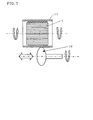
- a stuffing method shown in Fig. 3 using a guide 17
- a tourniquet method shown in Fig. 4 which comprises winding a metallic plate 11c round a honeycomb structure, pulling the plate to impart a pressure to the outer surface of the honeycomb structure, and welding and fixing the to-be-jointed areas of the metallic plate 11c
- a honeycomb structure between two metallic container parts 11a and 11b with a load being applied to the parts 11a and 11b, and welding the to-be-bonded areas (flanges) 16a and 16b of the parts 11a and 11b to obtain a honeycomb structure/metallic container integrated material.
- a method a swaging method utilizing metal plastic processing, shown in Fig. 6, which comprises applying a compression force to a metallic container 11 from the outside via a tap (of pressure type) to squeeze the outer diameter of the metallic container 11.
- a tap of pressure type
- the honeycomb segments used therein are allowed to load thereon a metal having a catalytic activity.
- a metal having a catalytic activity there are mentioned Pt, Pd, Rh, etc. It is preferred that at least one kind of these is loaded on the honeycomb segments.
- honeycomb structure or honeycomb structure assembly of the present invention is used as a filter for trapping and removing the particulate substance contained in an exhaust gas, for example, as a diesel particulate filter (DPF), it is preferred that the cells of honeycomb structure are plugged alternately at each structure end and the cell walls of honeycomb structure are used as a filter.
- DPF diesel particulate filter
- a method which comprises holding a honeycomb structure 1 in a metallic container 11 prior to catalyst loading, to form a honeycomb structure assembly 8, and then loading a catalyst on the honeycomb structure 1.
- the risk of chipping-off or breakage of honeycomb structure during catalyst loading can be prevented.
- the honeycomb structure or honeycomb structure assembly of the present invention is used as a catalytic converter, a catalyst component is loaded on a honeycomb segment 2, then a honeycomb structure 1 is formed, and the structure is accommodated and held in a metallic container 11.
- each of the following honeycomb structures of Examples and Conventional Examples is a filter used for trapping diesel fine particles, which is made of silicon carbide and has a cell wall thickness of 0.38 mm and a cell density of 31 cells/cm 2 and wherein the passages are plugged alternately at each end of honeycomb structure and the cell walls function as a filter.
- a silicon carbide powder was used as a raw material. Thereto were added methyl cellulose, hydroxypropoxyl methyl cellulose, a surfactant and water to prepare puddle having plasticity. This puddle was subjected to extrusion molding, and the resulting extrudate was dried using a microwave and hot air. Then, the holes of the dried extrudate were plugged alternately at each end of extrudate with a sealant made of the same material as for the honeycomb structure to be obtained, in such a way that each end of extrudate looked a checkerboard pattern.
- honeycomb segments 2 (v) which were each 1/4 of a column of about 144 mm in diameter and 152 mm in length and accordingly had a fan-shaped section.
- honeycomb segments 2 (v) were bonded into one piece by providing a ceramic fiber-made non-intumescent mat 3 at all the gaps formed by each two close faces of adjacent honeycomb segments 2 (v) and using a double sided tape, to obtain a honeycomb structure shown in Fig. 8(a).
- honeycomb structure was wound the same ceramic fiber-made non-intumescent mat as mentioned above; the mat-wound honeycomb structure was stuffed in a metallic (SUS 409) container using a tapered jig, to compression-fix the honeycomb structure and the metallic container, whereby a honeycomb structure assembly of 144 mm x 152 mm was obtained.
- a metallic (SUS 409) container using a tapered jig, to compression-fix the honeycomb structure and the metallic container, whereby a honeycomb structure assembly of 144 mm x 152 mm was obtained.
- Honeycomb segments 2 (w), 2(x) and (y) were obtained in the same manner as in Example 1. Twelve rectangular parallelepiped honeycomb segments 2 (w) of 30 mm x 30 mm x 152 mm, four honeycomb segments 2 (x) and eight honeycomb segments 2 (y) (total twenty four honeycomb segments) were bonded into one piece by providing a ceramic fiber-made non-intumescent mat 3 at all the gaps formed by each two close faces of adjacent honeycomb segments and using a double-coated tape, to obtain a honeycomb structure shown in Fig. 8(b).
- honeycomb structure was wound the same ceramic fiber-made non-intumescent mat as mentioned above; the mat-wound honeycomb structure was stuffed in a metallic (SUS 409) container using a tapered jig, to compression-fix the honeycomb structure and the metallic container, whereby a honeycomb structure assembly of 144 mm x 152 mm was obtained.
- a metallic (SUS 409) container using a tapered jig, to compression-fix the honeycomb structure and the metallic container, whereby a honeycomb structure assembly of 144 mm x 152 mm was obtained.
- honeycomb segments of 30 mm x 30 mm x 152 mm obtained in the same manner as in Example 1, one honeycomb segment 2 (x) and two honeycomb segments 2 (y) (total six honeycomb segments) were bonded using an adhesive 7 which was a mixture of colloidal silica, an alumina fiber and water, followed by drying to prepare four honeycomb segments which were each 1/4 of a column of about 144 mm in diameter and 152 mm in length and accordingly had a fan-shaped section.
- honeycomb segments were bonded into one piece by providing a ceramic fiber-made non-intumescent mat 3 at all the gaps formed by each two close faces of adjacent honeycomb segments and using a double-coated tape, to obtain a honeycomb structure shown in Fig.
- honeycomb segments 2 (w) of 30 mm x 30 mm x 152 mm obtained in the same manner as in Example 1, four honeycomb segments 2 (x) and eight honeycomb segments 2 (y) (total twenty four honeycomb segments) were bonded into one piece using the above-mentioned adhesive 7, followed by drying to obtain a honeycomb structure of 144 mm (diameter) x 152 mm, shown in Fig. 9(b).
- the thus-obtained honeycomb structure assemblies of Examples 1 to 3 and Comparative Examples 1 to 2 were comparatively evaluated by a hot vibration test.
- the test conditions were as follows.
- the vibration acceleration was set at 30 G (30 x 9.8 m/sec 2 ); the vibration frequency was set at 100 Hz; heating was conducted for 10 minutes using an exhaust gas having an inlet temperature of 800°C and a flow rate of 2.6 Nm 3 /min.) and cooling was made for 10 minutes to 100°C or less using air of ordinary temperature, and this heating and cooling cycle was continued until breakage of honeycomb structure took place or up to 200 hours.
- the honeycomb structure and honeycomb structure assembly of the present invention used a material A having compressive elasticity, at gaps formed by each two close faces of adjacent honeycomb segments; therefore, they showed good durability to heat and vibration.
Landscapes
- Chemical & Material Sciences (AREA)
- Chemical Kinetics & Catalysis (AREA)
- Engineering & Computer Science (AREA)
- Physics & Mathematics (AREA)
- Geometry (AREA)
- Environmental & Geological Engineering (AREA)
- Biomedical Technology (AREA)
- Oil, Petroleum & Natural Gas (AREA)
- General Chemical & Material Sciences (AREA)
- Analytical Chemistry (AREA)
- Health & Medical Sciences (AREA)
- Inorganic Chemistry (AREA)
- Combustion & Propulsion (AREA)
- Geology (AREA)
- Life Sciences & Earth Sciences (AREA)
- Ceramic Engineering (AREA)
- Thermal Sciences (AREA)
- Exhaust Gas After Treatment (AREA)
- Filtering Of Dispersed Particles In Gases (AREA)
- Filtering Materials (AREA)
- Processes For Solid Components From Exhaust (AREA)
- Catalysts (AREA)
- Fuel Cell (AREA)
- Exhaust Gas Treatment By Means Of Catalyst (AREA)
- Laminated Bodies (AREA)
Abstract
Description
Claims (13)
- A honeycomb structure obtained by bonding, into one piece, a plurality of honeycomb segments each having a large number of passages surrounded by cell walls and extending in the axial direction of the segment, characterized in that a material A having compressive elasticity is provided at least at a portion of the gaps formed by each two faces of adjacent honeycomb segments, close to each other.
- A honeycomb structure according to Claim 1, characterized in that the material A having compressive elasticity is a ceramic fiber-made mat.
- A honeycomb structure according to Claim 2, characterized in that the ceramic fiber-made mat is a non-intumescent mat composed mainly of alumina or mullite.
- A honeycomb structure according to any of Claims 1 to 3, characterized in that the honeycomb structure is used for purification of exhaust gas of automobile.
- A honeycomb structure according to any of Claims 1 to 4, characterized in that the honeycomb structure is used as a filter for trapping diesel fine particles.
- A honeycomb structure according to any of Claims 1 to 5, characterized in that the main component of the honeycomb segment comprises at least one kind of ceramic selected from the group consisting of silicon carbide, silicon nitride, cordierite, alumina, mullite, zirconia, zirconium phosphate, aluminum titanate, titania and combinations thereof, a Fe-Cr-Al type metal, a nickel-based metal, or metallic Si and SiC.
- A honeycomb structure assembly comprising
a metallic container,
a honeycomb structure according to any of Claims 1 to 6, obtained by bonding, into one piece, a plurality of honeycomb segments each having a large number of passages surrounded by cell walls and extending in the axial direction of the segment, wherein a material A having compressive elasticity is provided at least at a portion of the gaps formed by each two faces of adjacent honeycomb segments, close to each other, and
a material B having compressive elasticity, in which honeycomb structure assembly the material B having compressive elasticity is provided on the outer peripheral portion of the honeycomb structure in a compressed state and thereby the honeycomb structure is compression-held in the metallic container. - A honeycomb structure assembly according to Claim 7, characterized in that the material B having compressive elasticity is a ceramic fiber-made mat.
- A honeycomb structure assembly according to Claim 8, characterized in that the ceramic fiber-made mat is a non-intumescent mat composed mainly of alumina or mullite.
- A honeycomb structure assembly according to Claim 8, characterized in that the ceramic fiber-made mat is a heat-intumescent mat containing vermiculite.
- A honeycomb structure assembly according to any of Claims 7 to 10, characterized in that the honeycomb structure assembly is obtained by canning by a stuffing method, a tourniquet method, a clamshell method or a swaging method.
- A honeycomb structure assembly according to any of Claims 7 to 11, characterized in that the honeycomb structure assembly is obtained by loading a catalyst on the honeycomb segments and then accommodating the catalyst-loaded honeycomb segments in the metallic container.
- A honeycomb structure assembly according to any of Claims 7 to 11, characterized in that the honeycomb structure assembly is obtained by accommodating the honeycomb segments in the metallic container and then loading a catalyst on the honeycomb segments.
Applications Claiming Priority (3)
| Application Number | Priority Date | Filing Date | Title |
|---|---|---|---|
| JP2001095014A JP4511070B2 (en) | 2001-03-29 | 2001-03-29 | Honeycomb structure and assembly thereof |
| JP2001095014 | 2001-03-29 | ||
| PCT/JP2002/002106 WO2002079617A1 (en) | 2001-03-29 | 2002-03-07 | Honeycomb structure and assembly thereof |
Publications (3)
| Publication Number | Publication Date |
|---|---|
| EP1375852A1 true EP1375852A1 (en) | 2004-01-02 |
| EP1375852A4 EP1375852A4 (en) | 2004-10-20 |
| EP1375852B1 EP1375852B1 (en) | 2009-05-13 |
Family
ID=18949129
Family Applications (1)
| Application Number | Title | Priority Date | Filing Date |
|---|---|---|---|
| EP02702785A Expired - Lifetime EP1375852B1 (en) | 2001-03-29 | 2002-03-07 | Honeycomb structure and assembly thereof |
Country Status (5)
| Country | Link |
|---|---|
| US (1) | US7078086B2 (en) |
| EP (1) | EP1375852B1 (en) |
| JP (1) | JP4511070B2 (en) |
| DE (1) | DE60232320D1 (en) |
| WO (1) | WO2002079617A1 (en) |
Families Citing this family (22)
| Publication number | Priority date | Publication date | Assignee | Title |
|---|---|---|---|---|
| JP4511071B2 (en) * | 2001-03-29 | 2010-07-28 | 日本碍子株式会社 | Honeycomb structure and assembly thereof |
| PL1686108T3 (en) * | 2003-11-12 | 2012-02-29 | Ngk Insulators Ltd | Honeycomb structure |
| DE102004016690A1 (en) * | 2004-04-05 | 2005-10-27 | Arvin Technologies, Inc., Troy | Device for cleaning vehicle exhaust gases, in particular diesel soot filters, and vehicle with corresponding device |
| DE102004040549B4 (en) * | 2004-08-21 | 2017-03-23 | Umicore Ag & Co. Kg | Catalytically coated particle filter and its use |
| US7938877B2 (en) * | 2005-11-16 | 2011-05-10 | Geo2 Technologies, Inc. | Low coefficient of thermal expansion materials including modified aluminosilicate fibers and methods of manufacture |
| US7640732B2 (en) * | 2005-11-16 | 2010-01-05 | Geo2 Technologies, Inc. | Method and apparatus for filtration of a two-stroke engine exhaust |
| US7938876B2 (en) * | 2005-11-16 | 2011-05-10 | GE02 Technologies, Inc. | Low coefficient of thermal expansion materials including nonstoichiometric cordierite fibers and methods of manufacture |
| US8038759B2 (en) * | 2005-11-16 | 2011-10-18 | Geoz Technologies, Inc. | Fibrous cordierite materials |
| US20100048374A1 (en) * | 2005-11-16 | 2010-02-25 | James Jenq Liu | System and Method for Fabricating Ceramic Substrates |
| US20070107395A1 (en) * | 2005-11-16 | 2007-05-17 | Bilal Zuberi | Extruded porous substrate and products using the same |
| US20090166910A1 (en) * | 2005-11-16 | 2009-07-02 | Geo2 Technologies, Inc. | System and Method for Twin Screw Extrusion of a Fibrous Porous Substrate |
| US8039050B2 (en) * | 2005-12-21 | 2011-10-18 | Geo2 Technologies, Inc. | Method and apparatus for strengthening a porous substrate |
| JP4890903B2 (en) * | 2006-03-28 | 2012-03-07 | 日本碍子株式会社 | Honeycomb structure |
| FR2909896B1 (en) * | 2006-12-13 | 2009-02-06 | Jean Claude Fayard | FILTER MEDIA FOR EXHAUST GAS FILTRATION DEVICE OF DIESEL ENGINE, FILTER DEVICE AND GAS EXHAUST LINE OF INTERNAL COMBUSTION ENGINE IMPLEMENTING THE SAME |
| US20080178992A1 (en) * | 2007-01-31 | 2008-07-31 | Geo2 Technologies, Inc. | Porous Substrate and Method of Fabricating the Same |
| US7781372B2 (en) * | 2007-07-31 | 2010-08-24 | GE02 Technologies, Inc. | Fiber-based ceramic substrate and method of fabricating the same |
| US20100288704A1 (en) * | 2009-05-12 | 2010-11-18 | Jeffrey Michael Amsden | Flow-Through Substrate Assemblies and Methods for Making and Using Said Assemblies |
| JP2013204424A (en) * | 2012-03-27 | 2013-10-07 | Honda Motor Co Ltd | Catalytic converter device for exhaust emission control and saddle type vehicle |
| JP2014031754A (en) * | 2012-08-02 | 2014-02-20 | Ibiden Co Ltd | Exhaust emission control system, and method of manufacturing the same |
| WO2014061320A1 (en) * | 2012-10-19 | 2014-04-24 | 日本碍子株式会社 | Dust-collecting honeycomb filter |
| ITMI20122251A1 (en) * | 2012-12-28 | 2014-06-29 | Eni Spa | MULTI-TEXTURED REACTOR FOR CHEMICAL PROCESSES WITH HIGH HEAT EXCHANGE |
| JP6129609B2 (en) * | 2013-03-26 | 2017-05-17 | イビデン株式会社 | Exhaust gas purification device and method of manufacturing exhaust gas purification device |
Family Cites Families (24)
| Publication number | Priority date | Publication date | Assignee | Title |
|---|---|---|---|---|
| US6A (en) * | 1836-08-10 | Thomas Blanchard | Machine for forming end pieces of plank blocks for ships | |
| US9A (en) * | 1836-08-10 | Thomas Blanchard | Method of riveting plank or made blocks | |
| US1A (en) * | 1836-07-13 | John Ruggles | Locomotive steam-engine for rail and other roads | |
| US2000A (en) * | 1841-03-12 | Improvement in the manufacture of starch | ||
| JPS5546338A (en) | 1978-09-28 | 1980-04-01 | Ngk Insulators Ltd | Heat and shock resistant, revolving and heat-regenerating type ceramic heat exchanger body and its manufacturing |
| US4335783A (en) * | 1980-11-10 | 1982-06-22 | Corning Glass Works | Method for improving thermal shock resistance of honeycombed structures formed from joined cellular segments |
| JPH0163715U (en) * | 1987-10-20 | 1989-04-24 | ||
| JP2505261B2 (en) * | 1988-09-29 | 1996-06-05 | 日本碍子株式会社 | Ceramic heat exchanger and manufacturing method thereof |
| JPH0813706B2 (en) | 1991-07-02 | 1996-02-14 | 工業技術院長 | Silicon carbide / metal silicon composite and method for producing the same |
| JP2590943Y2 (en) * | 1992-10-22 | 1999-02-24 | イビデン株式会社 | Exhaust gas purification device |
| WO1994016134A1 (en) | 1993-01-07 | 1994-07-21 | Minnesota Mining And Manufacturing Company | Flexible nonwoven mat |
| JPH0769751A (en) | 1993-08-20 | 1995-03-14 | Minnesota Mining & Mfg Co <3M> | Laminated mat with edge protection for laminated mat and high temperature sealing material |
| US5866079A (en) * | 1993-09-03 | 1999-02-02 | Ngk Insulators, Ltd. | Ceramic honeycomb catalytic converter |
| JP2798874B2 (en) * | 1993-10-29 | 1998-09-17 | 日本碍子株式会社 | Ceramic honeycomb catalytic converter |
| JPH0842333A (en) | 1994-06-06 | 1996-02-13 | Ford Motor Co | Method for manufacturing catalyst exhaust treatment device |
| JP3121497B2 (en) | 1994-07-14 | 2000-12-25 | イビデン株式会社 | Ceramic structure |
| JP3294036B2 (en) * | 1995-01-26 | 2002-06-17 | 日本碍子株式会社 | Honeycomb catalytic converter |
| JPH09220480A (en) * | 1996-02-15 | 1997-08-26 | Nippon Steel Corp | Composite carrier for automobile exhaust gas purification |
| EP1093351A2 (en) * | 1998-06-29 | 2001-04-25 | The Procter & Gamble Company | Device for managing body fluids comprising a fast acquiring liquid handling member that expands upon liquid acquisition and contracts upon liquid release |
| JP2000210517A (en) * | 1999-01-20 | 2000-08-02 | Ngk Insulators Ltd | Method for holding ceramic filter, filter pack and filter device |
| JP3967034B2 (en) | 1999-03-30 | 2007-08-29 | イビデン株式会社 | Manufacturing method of ceramic filter unit |
| JP4409657B2 (en) * | 1999-03-30 | 2010-02-03 | イビデン株式会社 | Filter manufacturing method |
| JP4511065B2 (en) | 2000-06-05 | 2010-07-28 | 日本碍子株式会社 | Honeycomb structure, honeycomb filter, and manufacturing method thereof |
| JP4511071B2 (en) * | 2001-03-29 | 2010-07-28 | 日本碍子株式会社 | Honeycomb structure and assembly thereof |
-
2001
- 2001-03-29 JP JP2001095014A patent/JP4511070B2/en not_active Expired - Fee Related
-
2002
- 2002-03-07 DE DE60232320T patent/DE60232320D1/en not_active Expired - Lifetime
- 2002-03-07 WO PCT/JP2002/002106 patent/WO2002079617A1/en not_active Ceased
- 2002-03-07 US US10/469,380 patent/US7078086B2/en not_active Expired - Lifetime
- 2002-03-07 EP EP02702785A patent/EP1375852B1/en not_active Expired - Lifetime
Also Published As
| Publication number | Publication date |
|---|---|
| US7078086B2 (en) | 2006-07-18 |
| DE60232320D1 (en) | 2009-06-25 |
| JP2002282705A (en) | 2002-10-02 |
| US20040096625A1 (en) | 2004-05-20 |
| WO2002079617A1 (en) | 2002-10-10 |
| JP4511070B2 (en) | 2010-07-28 |
| EP1375852A4 (en) | 2004-10-20 |
| EP1375852B1 (en) | 2009-05-13 |
Similar Documents
| Publication | Publication Date | Title |
|---|---|---|
| US7041359B2 (en) | Honeycomb structure and assembly thereof | |
| EP1382374B1 (en) | Honeycomb structural body and assembly thereof | |
| EP1375852B1 (en) | Honeycomb structure and assembly thereof | |
| EP1375853B1 (en) | Honeycomb structure and assembly thereof | |
| US7384441B2 (en) | Honeycomb filter | |
| US7037567B2 (en) | Honeycomb structure | |
| EP1484483B1 (en) | Honeycomb filter | |
| EP1371406B1 (en) | Honeycomb structural body | |
| US7396576B2 (en) | Honeycomb structure | |
| EP1413345B1 (en) | Honeycomb structural body and method of manufacturing the structural body | |
| EP1473445A1 (en) | Honeycomb structure | |
| US8137637B2 (en) | Particulate filter and method of making | |
| JP2005113860A (en) | Particulate removal device |
Legal Events
| Date | Code | Title | Description |
|---|---|---|---|
| PUAI | Public reference made under article 153(3) epc to a published international application that has entered the european phase |
Free format text: ORIGINAL CODE: 0009012 |
|
| 17P | Request for examination filed |
Effective date: 20030911 |
|
| AK | Designated contracting states |
Kind code of ref document: A1 Designated state(s): AT BE CH CY DE DK ES FI FR GB GR IE IT LI LU MC NL PT SE TR |
|
| AX | Request for extension of the european patent |
Extension state: AL LT LV MK RO SI |
|
| RTI1 | Title (correction) |
Free format text: HONEYCOMB STRUCTURE AND ASSEMBLY THEREOF |
|
| A4 | Supplementary search report drawn up and despatched |
Effective date: 20040903 |
|
| RIC1 | Information provided on ipc code assigned before grant |
Ipc: 7B 01D 53/92 B Ipc: 7F 01N 3/28 B Ipc: 7B 01D 39/20 A Ipc: 7B 01J 35/04 B Ipc: 7B 32B 3/12 B Ipc: 7B 01D 46/00 B |
|
| 17Q | First examination report despatched |
Effective date: 20070702 |
|
| GRAP | Despatch of communication of intention to grant a patent |
Free format text: ORIGINAL CODE: EPIDOSNIGR1 |
|
| GRAS | Grant fee paid |
Free format text: ORIGINAL CODE: EPIDOSNIGR3 |
|
| GRAA | (expected) grant |
Free format text: ORIGINAL CODE: 0009210 |
|
| AK | Designated contracting states |
Kind code of ref document: B1 Designated state(s): DE FR |
|
| REF | Corresponds to: |
Ref document number: 60232320 Country of ref document: DE Date of ref document: 20090625 Kind code of ref document: P |
|
| PLBE | No opposition filed within time limit |
Free format text: ORIGINAL CODE: 0009261 |
|
| STAA | Information on the status of an ep patent application or granted ep patent |
Free format text: STATUS: NO OPPOSITION FILED WITHIN TIME LIMIT |
|
| 26N | No opposition filed |
Effective date: 20100216 |
|
| PGFP | Annual fee paid to national office [announced via postgrant information from national office to epo] |
Ref country code: FR Payment date: 20120328 Year of fee payment: 11 |
|
| REG | Reference to a national code |
Ref country code: FR Ref legal event code: ST Effective date: 20131129 |
|
| PG25 | Lapsed in a contracting state [announced via postgrant information from national office to epo] |
Ref country code: FR Free format text: LAPSE BECAUSE OF NON-PAYMENT OF DUE FEES Effective date: 20130402 |
|
| PGFP | Annual fee paid to national office [announced via postgrant information from national office to epo] |
Ref country code: DE Payment date: 20200225 Year of fee payment: 19 |
|
| REG | Reference to a national code |
Ref country code: DE Ref legal event code: R119 Ref document number: 60232320 Country of ref document: DE |
|
| PG25 | Lapsed in a contracting state [announced via postgrant information from national office to epo] |
Ref country code: DE Free format text: LAPSE BECAUSE OF NON-PAYMENT OF DUE FEES Effective date: 20211001 |