EP1375698A1 - Sputter device - Google Patents
Sputter device Download PDFInfo
- Publication number
- EP1375698A1 EP1375698A1 EP02707236A EP02707236A EP1375698A1 EP 1375698 A1 EP1375698 A1 EP 1375698A1 EP 02707236 A EP02707236 A EP 02707236A EP 02707236 A EP02707236 A EP 02707236A EP 1375698 A1 EP1375698 A1 EP 1375698A1
- Authority
- EP
- European Patent Office
- Prior art keywords
- auxiliary magnet
- magnet poles
- substrate
- angle
- magnetic field
- Prior art date
- Legal status (The legal status is an assumption and is not a legal conclusion. Google has not performed a legal analysis and makes no representation as to the accuracy of the status listed.)
- Granted
Links
Images





Classifications
-
- H—ELECTRICITY
- H01—ELECTRIC ELEMENTS
- H01J—ELECTRIC DISCHARGE TUBES OR DISCHARGE LAMPS
- H01J37/00—Discharge tubes with provision for introducing objects or material to be exposed to the discharge, e.g. for the purpose of examination or processing thereof
- H01J37/32—Gas-filled discharge tubes
- H01J37/34—Gas-filled discharge tubes operating with cathodic sputtering
- H01J37/3411—Constructional aspects of the reactor
- H01J37/345—Magnet arrangements in particular for cathodic sputtering apparatus
- H01J37/3455—Movable magnets
-
- C—CHEMISTRY; METALLURGY
- C23—COATING METALLIC MATERIAL; COATING MATERIAL WITH METALLIC MATERIAL; CHEMICAL SURFACE TREATMENT; DIFFUSION TREATMENT OF METALLIC MATERIAL; COATING BY VACUUM EVAPORATION, BY SPUTTERING, BY ION IMPLANTATION OR BY CHEMICAL VAPOUR DEPOSITION, IN GENERAL; INHIBITING CORROSION OF METALLIC MATERIAL OR INCRUSTATION IN GENERAL
- C23C—COATING METALLIC MATERIAL; COATING MATERIAL WITH METALLIC MATERIAL; SURFACE TREATMENT OF METALLIC MATERIAL BY DIFFUSION INTO THE SURFACE, BY CHEMICAL CONVERSION OR SUBSTITUTION; COATING BY VACUUM EVAPORATION, BY SPUTTERING, BY ION IMPLANTATION OR BY CHEMICAL VAPOUR DEPOSITION, IN GENERAL
- C23C14/00—Coating by vacuum evaporation, by sputtering or by ion implantation of the coating forming material
- C23C14/22—Coating by vacuum evaporation, by sputtering or by ion implantation of the coating forming material characterised by the process of coating
- C23C14/34—Sputtering
- C23C14/35—Sputtering by application of a magnetic field, e.g. magnetron sputtering
- C23C14/352—Sputtering by application of a magnetic field, e.g. magnetron sputtering using more than one target
-
- H—ELECTRICITY
- H01—ELECTRIC ELEMENTS
- H01J—ELECTRIC DISCHARGE TUBES OR DISCHARGE LAMPS
- H01J37/00—Discharge tubes with provision for introducing objects or material to be exposed to the discharge, e.g. for the purpose of examination or processing thereof
- H01J37/32—Gas-filled discharge tubes
- H01J37/34—Gas-filled discharge tubes operating with cathodic sputtering
- H01J37/3402—Gas-filled discharge tubes operating with cathodic sputtering using supplementary magnetic fields
- H01J37/3405—Magnetron sputtering
- H01J37/3408—Planar magnetron sputtering
Definitions
- the present invention relates to a sputtering apparatus for forming a thin layer by utilizing the magnetron sputtering method.
- the present applicant has proposed a technology for obtaining plasma having a high density in the surrounding of a substrate to be sputtered by disposing auxiliary magnet poles in the vicinity of magnetron type sputtering evaporation sources in order to confine with a high efficiency the plasma generated from the evaporation sources in the surrounding of a solid substance to be deposited, i.e., a substrate.
- magnetron type sputtering evaporation sources and auxiliary magnet poles are arranged in such a manner that they surround a solid substance to be deposited, in which case, the polarity of the auxiliary magnet poles is aligned so as to be opposite to the polarity of the outside magnet poles forming the magnetron for an evaporation source, so that the magnetic field is formed such that it surrounds the substrate so as to confine the plasma into the surrounding of the substrate.
- magnetron type sputtering evaporation sources and auxiliary magnet poles are arranged so as to surround a solid substance to be deposited, in which case the polarity of the auxiliary magnet poles is aligned in the same direction as the polarity of the outer magnet poles forming the magnetron for an evaporation source, so that the magnetic field is concentrated between the adjacent evaporation sources and the auxiliary poles, thereby enabling a plasma generated from the evaporation sources to be confined within the surrounding of the substrate by the mirror effect.
- an alteration of the shape of the magnetic field in the vicinity of the substrate makes it possible to adjust the density of the plasma in the vicinity of the substrate and, at the same time, to control the substrate bias current.
- the alteration of the shape of the magnetic field can be realized, for instance, by supplying an electric current to coils disposed on the rear surface of the evaporation sources.
- the coils are apart to some extent from the discharge space, the effect of alteration is relatively small and besides there appears a possible danger of disturbing the magnetic field above the evaporation sources.
- the shape of the magnetic field can be altered by remounting the auxiliary magnet poles to alter the polarity thereof in the direction to the substrate, after the auxiliary magnet poles are dismounted.
- this causes a great deal of work to be put for dismounting/mounting the auxiliary magnet poles, thereby causing a less workability to be provided.
- the dismounting /mounting of the auxiliary magnet poles provides setting only an S or N polarity in the direction towards the substrate and therefore only two types of the shape of the magnetic field are formed in the vicinity of the substrate, so that the shape of the magnetic field cannot be precisely altered.
- the auxiliary magnet poles are used to alter the shape of the magnetic field, and for this purpose the following techniques are employed:
- a sputtering apparatus wherein one or more magnetron type sputtering evaporation sources and one or more auxiliary magnet poles are arranged so as to enclose a solid substance to be deposited, wherein an angle changing mechanism is provided to change the alignment angle of said one or more auxiliary magnet pole relative to the solid substance to be deposited in order to alter the shape of the magnetic field which is produced by the magnetron type sputtering evaporation sources and the auxiliary magnet poles.
- the alteration of the alignment angle of the auxiliary magnet pole relative to the solid substance to be deposited by means of the changing mechanism for the auxiliary magnet poles allows the shape of the magnetic field to be intentionally altered, so that the density of plasma can be altered to a greater extent in the vicinity of the solid substance to be deposited (substrate). Furthermore, the adjustability of the substrate bias current permits the conditions of forming the layer at an optimal bias current to be selected in accordance with the type of the layer and the type of the substrate.
- the usage of coils is not required to alter the shape of the magnetic field, thereby enabling the cost of preparing the coils, a power supply for the coils and the like to be saved and, at the same time, allowing the disturbance in the magnetic field in the evaporation source to be excluded. Since, moreover, the system according to the invention provides an easier alteration of the shape of the magnetic field in a greater amount, compared with the coil system, the bias current can be adjusted in a wide range.
- the angle changing mechanism is capable of changing the alignment angle of the auxiliary magnet poles at an arbitrary value.
- the changeability of the auxiliary magnet poles in an arbitrary angle permits the shape of the magnetic field to be finely altered, so that the bias current can also be finely adjusted.
- the shape of the magnetic field can be altered easily even during the deposition process, if the angle changing mechanism can be driven during the deposition process.
- the mechanical power supply used for changing the angle of the auxiliary magnet poles for the angle changing mechanism is disposed outside the chamber, a simple structure can be provided.
- a manual manipulation unit disposed outside the chamber to manually operate the angle changing mechanism outside the chamber can be employed as a mechanical power supply.
- a driving apparatus for example, a motor or a pneumatic device for automatically changing the alignment angle of the auxiliary magnet poles by supplying a mechanical power to the direction changing mechanism from the outside can also be used as a mechanical power supply.
- auxiliary magnet poles when a plurality of auxiliary magnet poles is disposed, it is preferable that the alignment angle can be simultaneously changed for these auxiliary magnet poles. Such synchronization in the alignment of the auxiliary magnet poles allows the shape of the magnetic field to be totally altered.
- Fig. 1 shows a magnetron sputtering apparatus in a typical arrangement according to the invention, wherein four unbalance type magnetron sputtering evaporation sources are disposed.
- a substrate (a solid substance to be deposited) 2 is disposed at the center of a vacuum chamber 1 and four magnetron evaporation sources 3 are disposed in the vacuum chamber 1 such that they surround the substrate 2.
- Each of the magnetron evaporation sources 3 has the same structure and comprises a ring-shaped outside magnet pole 4, an inside magnet pole 5 mounted in the center of the outside magnet pole 4 and a target 6 made of a source material.
- each of the magnetron evaporation sources 3 is constituted in the form of an unbalance type magnetron evaporation source wherein the magnetic field strength in the outside magnet pole 4 forming the magnetron is greater than that in the inside magnet pole 5.
- the magnetron evaporation sources 3 are arranged at regular spacing around the substrate 2 in the form of a ring and disposed in the same distance apart from the substrate 2.
- Each auxiliary magnet pole 9 is disposed at the middle position between each two adjacent evaporation sources 3.
- Each auxiliary magnet pole 9 is constituted mainly by a permanent magnet.
- an inert gas such as argon
- argon is fed into the vacuum chamber 1.
- a glow discharge is generated between the vacuum chamber 1 and each magnetron evaporation source 3, and thereby plasma (electrons and argon ions) is produced inside the vacuum chamber 1.
- the argon ions in the vacuum chamber 1 collide with the target 6 in the evaporation source 3 made of the source material, so that metal atoms are evaporated from the magnetron evaporation source 3 (target 6) and then deposited onto the substrate 2, thus allowing a thin layer to be formed.
- the metal atoms are partially ionized in the vacuum chamber 1 and deposited at high energy onto the substrate 2, which is electrically biased at a negative potential.
- the magnetron sputtering apparatus is equipped with the auxiliary magnet poles, plasma generated from the evaporation source 3 is concentrated at a higher density around the substrate 2, so that the ionization of metal atoms evaporated from the evaporation source 3 is promoted.
- the ions collide with the layer formed on the substrate in a greater frequency, thereby enabling the adhesive force to the substrate 2 to be greatly enhanced and the layer structure to be effectively improved.
- each auxiliary magnet pole 9 in Fig. 1, the polarity of each auxiliary magnet pole 9 relative to the substrate 2 is different from the polarity of the outside magnet pole 4 in the magnetron evaporation source 3.
- the auxiliary magnet pole 9 can be rotated by 360 degrees in the direction of the arrow indicted in Fig. 1, and can be further set at an arbitrary angle position.
- the polarity of the auxiliary magnet pole in the direction to the substrate is N and therefore is the same as the polarity of the outside magnet pole 4 in the magnetron evaporation source 3.
- Fig. 4 shows the numerically analyzed result for the field strength distribution of a magnetic field in the sputtering apparatus shown in Fig. 1 (the analyzed area being a quarter of the vacuum chamber).
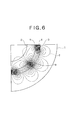
- Figs. 5 and 6 show the numerically analyzed results for the field strength distribution of a magnetic field in the sputtering apparatus shown in Fig. 2 and 3, respectively.
- numeral 7 indicates a line of magnetic force in Figs. 4 to 6.
- a rotation of the auxiliary magnet pole 9 provides a significant alteration in the shape of the magnetic field. Moreover, it can be recognized that the shape of the magnetic field can be finely altered, when the alignment angle of the auxiliary magnet pole 9 is slightly changed within the range where the polarity of the auxiliary magnet pole 9 in the direction to substrate 2 is changed from N to S.
- Fig. 7 shows the results of the bias current measured in the substrate 2 for the respective alignment angles of the auxiliary magnet poles 9, when the plasma is produced from argon gas. From the results shown in Fig. 7, it can be seen that an alteration of the rotary angle ⁇ of the auxiliary magnet pole 9 allows the substrate bias current to be changed in a wide range.
- lines of magnetic force 11 are formed such that they sequentially connect each auxiliary magnet pole to the adjacent outside magnet pole in the corresponding magnetron evaporation source 3 in an alternating manner, so that a magnetic field is formed by the evaporators 3 and the auxiliary magnet poles 4 such that it surrounds the substrate 2, and thereby the plasma generated from the evaporators 3 can be confined within the circumference of the substrate 2.
- the magnetic fields generated from the outside magnetic poles 4 in the respective evaporation sources 3 and those generated from the respective auxiliary magnet poles 9 repel each other in the middle area between the outside magnet poles 4 and the auxiliary magnet poles 9. Accordingly, the magnetic fluxes are not concentrated in this area and thus the plasma generated by the glow discharge can be confined within the circumference of the substrate 2 by the mirror effect.
- the magnetic fields from the evaporator source 3 and that from the auxiliary magnet pole 9 repel each other, and therefore the magnetic fields in front of the evaporator sources 3 swell in the direction to the substrate 2 and lines of magnetic force connecting the auxiliary magnet poles 9 to the inside magnet poles 5 in the evaporation source 3 are also produced, so that the plasma expands in the direction to the substrate 2 and high density plasma is produced above the substrate 2.
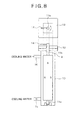
- Fig. 8 shows an angle changing mechanism for the auxiliary magnetic poles 9.
- the angle changing mechanism is constituted such that a permanent magnet 8 in each auxiliary magnet pole 9 can be rotated.
- the auxiliary magnet pole 9 comprises the permanent magnet 8 in a magnet holder 10, and the angle changing mechanism is designed such that the rotary shafts 11a and 11b extending respectively from the upper and lower ends of the permanent magnet 8 are rotatably supported by the magnet holder 10 and the permanent magnet 8 can be rotated around the axis of the permanent magnet 8.
- the S pole of the magnet 8 is positioned on the side of substrate 2 (on the right hand side in Fig. 8) and the N pole is positioned at the opposite side (corresponding to the state in Fig. 1).
- a rotation of the magnet 8 provides the state shown either in Fig. 2 or in Fig. 3.
- the upper rotary shaft 11b extends from the flange 12 at the upper part of the holder 10 into the outside of the holder 10, and a handle 14 is disposed as a manual operation unit in the rotary shaft 11b outside the holder 10.
- a rotation of the handle 14 by manipulation outside the holder 10 provides a rotation of the rotary shafts 11a, 11b and permanent magnet 8, thereby enabling the shape of the magnetic field to be altered.
- the holder 10 has a feed opening 15 for feeding the cooling water from the outside of the chamber 1 and a discharge opening 16 for discharging the cooling water to the outside thereof, and therefore serves as a cooling space for cooling the magnet 8 by circulating the cooling water inside the holder 10.
- Fig. 9 shows another embodiment of the angle changing mechanism.
- the angle changing mechanism is designed such that the whole structure of the auxiliary magnet pole 9 can be rotated.
- the auxiliary magnet pole 9 is equipped with the permanent magnet 8 in the magnet holder 10.
- the angle changing mechanism is constituted such that the rotary shafts 17a and 17b extending respectively from the upper and lower ends of the holder 10 are rotatably supported on the chamber 1 and the holder 10 can be rotated around the longitudinal axis together with the magnet 8.
- the magnet 8 has an S pole on the side of the substrate 2 (on the right hand side in Fig. 9) and an N pole on the opposite side (corresponding to the state in Fig. 1).
- a rotation of the magnet 8 provides such a state as shown either in Fig. 2 or in Fig. 3.
- the upper rotary shaft 17b is disposed such that it passes through the wall outside of the chamber 1 in the form of a projection.
- a handle 14 is disposed as a manually manipulating element at the rotary shaft 17 outside the chamber 1.
- a rotation of the handle 14 by manipulation outside the chamber 1 provides a rotation of the rotary shafts 17a and 17b, and further provides a rotation of the permanent magnet 8 together with the holder 10, thereby allowing the shape of the magnetic field to be altered.
- the upper and lower rotary shafts 17a and 17b are be used as pipes for supplying and discharging the cooling water into/from the holder 10, which serves as a cooling space.
- Fig. 10 shows a driving apparatus comprising a motor 19 for rotating the rotary shaft 11b in Fig. 8.
- the magnet 8 can be automatically rotated by means of the rotary force supplied from the motor 19.
- the magnet 8 can also be automatically rotated, if the handle 14 is replaced with a motor.
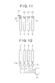
- a synchronized driving mechanism shown in Fig. 11 can be used to change the alignment angle of the auxiliary magnet poles in synchronization with each other.
- the synchronized driving mechanism is used to transmit a rotary power resulting from the handle 14 to the respective auxiliary magnet poles 9 arranged in the form of a ring for the apparatus including the handle 14, as shown in Fig. 8 or 9.
- the synchronized driving mechanism comprises rotary elements 20, such as pulleys or sprockets, mounted on the rotary shaft 11b of the respective auxiliary magnet poles 9 and a mechanical power transmission element 21, such as a belt or a chain.
- a rotation of the handle 14 causes the rotary elements 20 to be rotated either directly or via the mechanical power transmission element 21.
- the alignment angles of the respective auxiliary magnet poles 9 can be changed in synchronization with each other, thereby enabling the whole shape of the magnetic field in the chamber 1.
- a driving apparatus such as a motor or the like, as shown in Fig. 10, can be used in lieu of the handle shown in Fig. 11.
- a driving apparatus 21 is mounted on each auxiliary magnet pole 9, as shown in Fig. 12, and the respective driving apparatuses 21 are controlled to be rotated in synchronization with each other by a control unit 22.
- the present invention is effective for a sputtering apparatus for forming a thin layer by utilizing the magnetron sputtering method.
Landscapes
- Chemical & Material Sciences (AREA)
- Engineering & Computer Science (AREA)
- Physics & Mathematics (AREA)
- Plasma & Fusion (AREA)
- Analytical Chemistry (AREA)
- Materials Engineering (AREA)
- Chemical Kinetics & Catalysis (AREA)
- Mechanical Engineering (AREA)
- Metallurgy (AREA)
- Organic Chemistry (AREA)
- Physical Vapour Deposition (AREA)
- Physical Or Chemical Processes And Apparatus (AREA)
- Physical Deposition Of Substances That Are Components Of Semiconductor Devices (AREA)
Abstract
Description
Claims (6)
- A sputtering apparatus wherein one or more magnetron type sputtering evaporation sources (3) and one or more auxiliary magnet poles (9) are disposed in a chamber (1) so as to surround a solid substance (2) to be deposited,
wherein an angle changing mechanism for changing the alignment angle of said auxiliary magnet poles (9) relative to said solid substance (2) to be deposited in order to alter the shape of the magnetic field formed by said magnetron type sputtering evaporation sources (3) and said auxiliary magnet poles (9). - The sputtering apparatus according to Claim 1, wherein said angle changing mechanism is designed such that said auxiliary magnet pole (9) can be aligned in an arbitrary angle.
- The sputtering apparatus according to Claim 1, wherein a mechanical power supply unit (14, 19) for supplying a mechanical power to said angle changing mechanism to change the alignment angle is disposed outside said chamber (1).
- The sputtering apparatus according to Claim 3, wherein said mechanical power supply unit is a manual manipulation unit (14) disposed outside said chamber (1) to manually drive said angle changing mechanism outside the chamber (1).
- The sputtering apparatus according to Claim 3, wherein said mechanical power supply unit is a driving apparatus (19) for supplying a mechanical power to said angle changing mechanism outside the chamber (1) to automatically change the alignment angle of the auxiliary magnet pole (9).
- The sputtering apparatus according to Claim 1, wherein a plurality of said auxiliary magnet poles (9) is disposed and said auxiliary magnet poles (9) are designed such that the alignment angles thereof can be changed in synchronization.
Applications Claiming Priority (3)
| Application Number | Priority Date | Filing Date | Title |
|---|---|---|---|
| JP2001100720A JP4219566B2 (en) | 2001-03-30 | 2001-03-30 | Sputtering equipment |
| JP2001100720 | 2001-03-30 | ||
| PCT/JP2002/003134 WO2002079536A1 (en) | 2001-03-30 | 2002-03-28 | Sputter device |
Publications (3)
| Publication Number | Publication Date |
|---|---|
| EP1375698A1 true EP1375698A1 (en) | 2004-01-02 |
| EP1375698A4 EP1375698A4 (en) | 2006-09-27 |
| EP1375698B1 EP1375698B1 (en) | 2017-11-15 |
Family
ID=18954140
Family Applications (1)
| Application Number | Title | Priority Date | Filing Date |
|---|---|---|---|
| EP02707236.2A Expired - Lifetime EP1375698B1 (en) | 2001-03-30 | 2002-03-28 | Sputter device |
Country Status (4)
| Country | Link |
|---|---|
| US (1) | US6749730B2 (en) |
| EP (1) | EP1375698B1 (en) |
| JP (1) | JP4219566B2 (en) |
| WO (1) | WO2002079536A1 (en) |
Families Citing this family (7)
| Publication number | Priority date | Publication date | Assignee | Title |
|---|---|---|---|---|
| KR20060033013A (en) * | 2003-07-14 | 2006-04-18 | 토소우 에스엠디, 인크 | Sputtering target assembly with low conducting backing plate and manufacturing method thereof |
| CN101035925B (en) * | 2004-09-08 | 2010-09-08 | 比克-维奥利克斯公司 | Method of depositing a coating on razor blade edges and razor blades |
| US20090294281A1 (en) * | 2006-07-07 | 2009-12-03 | Canon Anelva Corporation | Plasma film forming apparatus and film manufacturing method |
| GB0613510D0 (en) * | 2006-07-07 | 2006-08-16 | Teer Coatings Ltd | A method and apparatus for the formation of coatings on drills |
| WO2009040892A1 (en) * | 2007-09-26 | 2009-04-02 | Canon Anelva Corporation | Magnet assembly capable of generating magnetic field whose direction is uniform and changeable and sputtering device using same |
| CZ304905B6 (en) | 2009-11-23 | 2015-01-14 | Shm, S.R.O. | Method of depositing PVD layers, using cylindrical rotating cathode and apparatus for making the same |
| PL2811507T3 (en) * | 2013-06-07 | 2020-09-07 | Soleras Advanced Coatings Bvba | Magnetic configuration for a magnetron sputter deposition system |
Family Cites Families (13)
| Publication number | Priority date | Publication date | Assignee | Title |
|---|---|---|---|---|
| JPS6357765A (en) | 1986-08-26 | 1988-03-12 | Hitachi Metals Ltd | Sputtering device |
| JP2643149B2 (en) * | 1987-06-03 | 1997-08-20 | 株式会社ブリヂストン | Surface treatment method |
| JPH0768617B2 (en) * | 1988-04-18 | 1995-07-26 | 日電アネルバ株式会社 | Magnetron sputtering equipment |
| JP2794744B2 (en) | 1989-01-20 | 1998-09-10 | 株式会社ブリヂストン | Coating method |
| JP2766010B2 (en) | 1989-12-19 | 1998-06-18 | 沖電気工業株式会社 | Magnetic field generator and dry process apparatus having the same |
| DE4038497C1 (en) * | 1990-12-03 | 1992-02-20 | Leybold Ag, 6450 Hanau, De | |
| JP3190127B2 (en) | 1992-07-09 | 2001-07-23 | 日本合成化学工業株式会社 | Photosensitive resin composition and use thereof |
| JP2970317B2 (en) * | 1993-06-24 | 1999-11-02 | 松下電器産業株式会社 | Sputtering apparatus and sputtering method |
| GB9700158D0 (en) * | 1997-01-07 | 1997-02-26 | Gencoa Limited | Versatile coating deposition system |
| JPH11172432A (en) * | 1997-12-16 | 1999-06-29 | Hitachi Ltd | Magnetic film forming equipment |
| GB2340845B (en) * | 1998-08-19 | 2001-01-31 | Kobe Steel Ltd | Magnetron sputtering apparatus |
| JP3803520B2 (en) | 1999-02-22 | 2006-08-02 | 忠弘 大見 | Magnet rotation sputtering equipment |
| JP3414667B2 (en) * | 1999-03-23 | 2003-06-09 | 三容真空工業株式会社 | Magnetron sputtering method |
-
2001
- 2001-03-30 JP JP2001100720A patent/JP4219566B2/en not_active Expired - Fee Related
-
2002
- 2002-03-28 EP EP02707236.2A patent/EP1375698B1/en not_active Expired - Lifetime
- 2002-03-28 US US10/344,365 patent/US6749730B2/en not_active Expired - Lifetime
- 2002-03-28 WO PCT/JP2002/003134 patent/WO2002079536A1/en not_active Ceased
Also Published As
| Publication number | Publication date |
|---|---|
| WO2002079536A1 (en) | 2002-10-10 |
| EP1375698A4 (en) | 2006-09-27 |
| JP2002294447A (en) | 2002-10-09 |
| JP4219566B2 (en) | 2009-02-04 |
| US6749730B2 (en) | 2004-06-15 |
| EP1375698B1 (en) | 2017-11-15 |
| US20030155236A1 (en) | 2003-08-21 |
Similar Documents
| Publication | Publication Date | Title |
|---|---|---|
| JP4491132B2 (en) | Plasma processing equipment | |
| US6113752A (en) | Method and device for coating substrate | |
| US4842703A (en) | Magnetron cathode and method for sputter coating | |
| EP0495447A1 (en) | Method of controlling an arc spot in vacuum arc vapor deposition and an evaporation source | |
| US5626727A (en) | Sputtering apparatus and method | |
| US8377269B2 (en) | Sputtering apparatus | |
| US20060196766A1 (en) | Plasma deposition apparatus and method | |
| EP2626887A1 (en) | Online adjustable magnet bar | |
| KR20220020426A (en) | Method of HIPIMS sputtering and HIPIMS sputter system | |
| US6156170A (en) | Magnetron sputtering apparatus | |
| EP2164091B1 (en) | Method for manufacturing sputter-coated substrates, magnetron source and sputtering chamber with such source | |
| US5690796A (en) | Method and apparatus for layer depositions | |
| US6749730B2 (en) | Sputter device | |
| US20060175190A1 (en) | Vacuum arc source comprising a device for generating a magnetic field | |
| JPH0747821B2 (en) | Equipment for coating components by cathodic sputtering | |
| EP1211332A1 (en) | Magnetron unit and sputtering device | |
| KR100530545B1 (en) | Apparatus for driving the arc in a cathodic arc coater | |
| EP1170776A2 (en) | Vacuum arc evaporation source and film formation apparatus using the same | |
| US12176191B2 (en) | Magnetron design for improved bottom coverage and uniformity | |
| JPH02111878A (en) | Sputtering device | |
| JP2946387B2 (en) | Ion plating equipment | |
| KR20010021341A (en) | Arc type ion plating apparatus | |
| US9558921B2 (en) | Magnetron sputtering apparatus | |
| JP2009108383A (en) | Target device and magnetron sputtering device | |
| JP3766569B2 (en) | Magnetron sputtering equipment |
Legal Events
| Date | Code | Title | Description |
|---|---|---|---|
| PUAI | Public reference made under article 153(3) epc to a published international application that has entered the european phase |
Free format text: ORIGINAL CODE: 0009012 |
|
| 17P | Request for examination filed |
Effective date: 20021230 |
|
| AK | Designated contracting states |
Kind code of ref document: A1 Designated state(s): AT BE CH CY DE DK ES FI FR GB GR IE IT LI LU MC NL PT SE TR |
|
| AX | Request for extension of the european patent |
Extension state: AL LT LV MK RO SI |
|
| A4 | Supplementary search report drawn up and despatched |
Effective date: 20060830 |
|
| RIC1 | Information provided on ipc code assigned before grant |
Ipc: H01J 37/34 20060101AFI20060824BHEP Ipc: C23C 14/35 20060101ALI20060824BHEP |
|
| 17Q | First examination report despatched |
Effective date: 20080725 |
|
| GRAP | Despatch of communication of intention to grant a patent |
Free format text: ORIGINAL CODE: EPIDOSNIGR1 |
|
| STAA | Information on the status of an ep patent application or granted ep patent |
Free format text: STATUS: GRANT OF PATENT IS INTENDED |
|
| INTG | Intention to grant announced |
Effective date: 20170613 |
|
| GRAS | Grant fee paid |
Free format text: ORIGINAL CODE: EPIDOSNIGR3 |
|
| GRAA | (expected) grant |
Free format text: ORIGINAL CODE: 0009210 |
|
| STAA | Information on the status of an ep patent application or granted ep patent |
Free format text: STATUS: THE PATENT HAS BEEN GRANTED |
|
| AK | Designated contracting states |
Kind code of ref document: B1 Designated state(s): AT BE CH CY DE DK ES FI FR GB GR IE IT LI LU MC NL PT SE TR |
|
| REG | Reference to a national code |
Ref country code: CH Ref legal event code: EP Ref country code: GB Ref legal event code: FG4D Ref country code: AT Ref legal event code: REF Ref document number: 947043 Country of ref document: AT Kind code of ref document: T Effective date: 20171115 |
|
| REG | Reference to a national code |
Ref country code: IE Ref legal event code: FG4D |
|
| REG | Reference to a national code |
Ref country code: DE Ref legal event code: R096 Ref document number: 60249165 Country of ref document: DE |
|
| REG | Reference to a national code |
Ref country code: NL Ref legal event code: FP |
|
| REG | Reference to a national code |
Ref country code: AT Ref legal event code: MK05 Ref document number: 947043 Country of ref document: AT Kind code of ref document: T Effective date: 20171115 |
|
| PG25 | Lapsed in a contracting state [announced via postgrant information from national office to epo] |
Ref country code: ES Free format text: LAPSE BECAUSE OF FAILURE TO SUBMIT A TRANSLATION OF THE DESCRIPTION OR TO PAY THE FEE WITHIN THE PRESCRIBED TIME-LIMIT Effective date: 20171115 Ref country code: SE Free format text: LAPSE BECAUSE OF FAILURE TO SUBMIT A TRANSLATION OF THE DESCRIPTION OR TO PAY THE FEE WITHIN THE PRESCRIBED TIME-LIMIT Effective date: 20171115 Ref country code: FI Free format text: LAPSE BECAUSE OF FAILURE TO SUBMIT A TRANSLATION OF THE DESCRIPTION OR TO PAY THE FEE WITHIN THE PRESCRIBED TIME-LIMIT Effective date: 20171115 |
|
| PG25 | Lapsed in a contracting state [announced via postgrant information from national office to epo] |
Ref country code: GR Free format text: LAPSE BECAUSE OF FAILURE TO SUBMIT A TRANSLATION OF THE DESCRIPTION OR TO PAY THE FEE WITHIN THE PRESCRIBED TIME-LIMIT Effective date: 20180216 Ref country code: AT Free format text: LAPSE BECAUSE OF FAILURE TO SUBMIT A TRANSLATION OF THE DESCRIPTION OR TO PAY THE FEE WITHIN THE PRESCRIBED TIME-LIMIT Effective date: 20171115 |
|
| PG25 | Lapsed in a contracting state [announced via postgrant information from national office to epo] |
Ref country code: CY Free format text: LAPSE BECAUSE OF FAILURE TO SUBMIT A TRANSLATION OF THE DESCRIPTION OR TO PAY THE FEE WITHIN THE PRESCRIBED TIME-LIMIT Effective date: 20171115 Ref country code: DK Free format text: LAPSE BECAUSE OF FAILURE TO SUBMIT A TRANSLATION OF THE DESCRIPTION OR TO PAY THE FEE WITHIN THE PRESCRIBED TIME-LIMIT Effective date: 20171115 |
|
| REG | Reference to a national code |
Ref country code: DE Ref legal event code: R097 Ref document number: 60249165 Country of ref document: DE |
|
| PG25 | Lapsed in a contracting state [announced via postgrant information from national office to epo] |
Ref country code: IT Free format text: LAPSE BECAUSE OF FAILURE TO SUBMIT A TRANSLATION OF THE DESCRIPTION OR TO PAY THE FEE WITHIN THE PRESCRIBED TIME-LIMIT Effective date: 20171115 |
|
| PLBE | No opposition filed within time limit |
Free format text: ORIGINAL CODE: 0009261 |
|
| STAA | Information on the status of an ep patent application or granted ep patent |
Free format text: STATUS: NO OPPOSITION FILED WITHIN TIME LIMIT |
|
| 26N | No opposition filed |
Effective date: 20180817 |
|
| REG | Reference to a national code |
Ref country code: CH Ref legal event code: PL |
|
| GBPC | Gb: european patent ceased through non-payment of renewal fee |
Effective date: 20180328 |
|
| PG25 | Lapsed in a contracting state [announced via postgrant information from national office to epo] |
Ref country code: MC Free format text: LAPSE BECAUSE OF FAILURE TO SUBMIT A TRANSLATION OF THE DESCRIPTION OR TO PAY THE FEE WITHIN THE PRESCRIBED TIME-LIMIT Effective date: 20171115 |
|
| REG | Reference to a national code |
Ref country code: BE Ref legal event code: MM Effective date: 20180331 |
|
| REG | Reference to a national code |
Ref country code: IE Ref legal event code: MM4A |
|
| PG25 | Lapsed in a contracting state [announced via postgrant information from national office to epo] |
Ref country code: LU Free format text: LAPSE BECAUSE OF NON-PAYMENT OF DUE FEES Effective date: 20180328 |
|
| PG25 | Lapsed in a contracting state [announced via postgrant information from national office to epo] |
Ref country code: IE Free format text: LAPSE BECAUSE OF NON-PAYMENT OF DUE FEES Effective date: 20180328 |
|
| PG25 | Lapsed in a contracting state [announced via postgrant information from national office to epo] |
Ref country code: LI Free format text: LAPSE BECAUSE OF NON-PAYMENT OF DUE FEES Effective date: 20180331 Ref country code: BE Free format text: LAPSE BECAUSE OF NON-PAYMENT OF DUE FEES Effective date: 20180331 Ref country code: CH Free format text: LAPSE BECAUSE OF NON-PAYMENT OF DUE FEES Effective date: 20180331 Ref country code: GB Free format text: LAPSE BECAUSE OF NON-PAYMENT OF DUE FEES Effective date: 20180328 |
|
| PG25 | Lapsed in a contracting state [announced via postgrant information from national office to epo] |
Ref country code: FR Free format text: LAPSE BECAUSE OF NON-PAYMENT OF DUE FEES Effective date: 20180331 |
|
| PGFP | Annual fee paid to national office [announced via postgrant information from national office to epo] |
Ref country code: DE Payment date: 20190312 Year of fee payment: 18 |
|
| PGFP | Annual fee paid to national office [announced via postgrant information from national office to epo] |
Ref country code: NL Payment date: 20190313 Year of fee payment: 18 |
|
| PG25 | Lapsed in a contracting state [announced via postgrant information from national office to epo] |
Ref country code: TR Free format text: LAPSE BECAUSE OF FAILURE TO SUBMIT A TRANSLATION OF THE DESCRIPTION OR TO PAY THE FEE WITHIN THE PRESCRIBED TIME-LIMIT Effective date: 20171115 |
|
| PG25 | Lapsed in a contracting state [announced via postgrant information from national office to epo] |
Ref country code: PT Free format text: LAPSE BECAUSE OF FAILURE TO SUBMIT A TRANSLATION OF THE DESCRIPTION OR TO PAY THE FEE WITHIN THE PRESCRIBED TIME-LIMIT Effective date: 20171115 |
|
| REG | Reference to a national code |
Ref country code: DE Ref legal event code: R119 Ref document number: 60249165 Country of ref document: DE |
|
| REG | Reference to a national code |
Ref country code: NL Ref legal event code: MM Effective date: 20200401 |
|
| PG25 | Lapsed in a contracting state [announced via postgrant information from national office to epo] |
Ref country code: NL Free format text: LAPSE BECAUSE OF NON-PAYMENT OF DUE FEES Effective date: 20200401 |
|
| PG25 | Lapsed in a contracting state [announced via postgrant information from national office to epo] |
Ref country code: DE Free format text: LAPSE BECAUSE OF NON-PAYMENT OF DUE FEES Effective date: 20201001 |