EP1375620B1 - Apparatus for bonding plate-shaped objects together and method for bonding plate-shaped objects together - Google Patents
Apparatus for bonding plate-shaped objects together and method for bonding plate-shaped objects together Download PDFInfo
- Publication number
- EP1375620B1 EP1375620B1 EP02712295A EP02712295A EP1375620B1 EP 1375620 B1 EP1375620 B1 EP 1375620B1 EP 02712295 A EP02712295 A EP 02712295A EP 02712295 A EP02712295 A EP 02712295A EP 1375620 B1 EP1375620 B1 EP 1375620B1
- Authority
- EP
- European Patent Office
- Prior art keywords
- plate
- shaped object
- time point
- adhesive
- contact
- Prior art date
- Legal status (The legal status is an assumption and is not a legal conclusion. Google has not performed a legal analysis and makes no representation as to the accuracy of the status listed.)
- Expired - Lifetime
Links
Images


Classifications
-
- B—PERFORMING OPERATIONS; TRANSPORTING
- B29—WORKING OF PLASTICS; WORKING OF SUBSTANCES IN A PLASTIC STATE IN GENERAL
- B29C—SHAPING OR JOINING OF PLASTICS; SHAPING OF MATERIAL IN A PLASTIC STATE, NOT OTHERWISE PROVIDED FOR; AFTER-TREATMENT OF THE SHAPED PRODUCTS, e.g. REPAIRING
- B29C65/00—Joining or sealing of preformed parts, e.g. welding of plastics materials; Apparatus therefor
- B29C65/48—Joining or sealing of preformed parts, e.g. welding of plastics materials; Apparatus therefor using adhesives, i.e. using supplementary joining material; solvent bonding
- B29C65/52—Joining or sealing of preformed parts, e.g. welding of plastics materials; Apparatus therefor using adhesives, i.e. using supplementary joining material; solvent bonding characterised by the way of applying the adhesive
-
- B—PERFORMING OPERATIONS; TRANSPORTING
- B29—WORKING OF PLASTICS; WORKING OF SUBSTANCES IN A PLASTIC STATE IN GENERAL
- B29C—SHAPING OR JOINING OF PLASTICS; SHAPING OF MATERIAL IN A PLASTIC STATE, NOT OTHERWISE PROVIDED FOR; AFTER-TREATMENT OF THE SHAPED PRODUCTS, e.g. REPAIRING
- B29C65/00—Joining or sealing of preformed parts, e.g. welding of plastics materials; Apparatus therefor
- B29C65/48—Joining or sealing of preformed parts, e.g. welding of plastics materials; Apparatus therefor using adhesives, i.e. using supplementary joining material; solvent bonding
-
- B—PERFORMING OPERATIONS; TRANSPORTING
- B29—WORKING OF PLASTICS; WORKING OF SUBSTANCES IN A PLASTIC STATE IN GENERAL
- B29C—SHAPING OR JOINING OF PLASTICS; SHAPING OF MATERIAL IN A PLASTIC STATE, NOT OTHERWISE PROVIDED FOR; AFTER-TREATMENT OF THE SHAPED PRODUCTS, e.g. REPAIRING
- B29C65/00—Joining or sealing of preformed parts, e.g. welding of plastics materials; Apparatus therefor
- B29C65/48—Joining or sealing of preformed parts, e.g. welding of plastics materials; Apparatus therefor using adhesives, i.e. using supplementary joining material; solvent bonding
- B29C65/4805—Joining or sealing of preformed parts, e.g. welding of plastics materials; Apparatus therefor using adhesives, i.e. using supplementary joining material; solvent bonding characterised by the type of adhesives
- B29C65/483—Reactive adhesives, e.g. chemically curing adhesives
-
- B—PERFORMING OPERATIONS; TRANSPORTING
- B29—WORKING OF PLASTICS; WORKING OF SUBSTANCES IN A PLASTIC STATE IN GENERAL
- B29C—SHAPING OR JOINING OF PLASTICS; SHAPING OF MATERIAL IN A PLASTIC STATE, NOT OTHERWISE PROVIDED FOR; AFTER-TREATMENT OF THE SHAPED PRODUCTS, e.g. REPAIRING
- B29C66/00—General aspects of processes or apparatus for joining preformed parts
- B29C66/01—General aspects dealing with the joint area or with the area to be joined
- B29C66/05—Particular design of joint configurations
- B29C66/10—Particular design of joint configurations particular design of the joint cross-sections
- B29C66/11—Joint cross-sections comprising a single joint-segment, i.e. one of the parts to be joined comprising a single joint-segment in the joint cross-section
- B29C66/112—Single lapped joints
- B29C66/1122—Single lap to lap joints, i.e. overlap joints
-
- B—PERFORMING OPERATIONS; TRANSPORTING
- B29—WORKING OF PLASTICS; WORKING OF SUBSTANCES IN A PLASTIC STATE IN GENERAL
- B29C—SHAPING OR JOINING OF PLASTICS; SHAPING OF MATERIAL IN A PLASTIC STATE, NOT OTHERWISE PROVIDED FOR; AFTER-TREATMENT OF THE SHAPED PRODUCTS, e.g. REPAIRING
- B29C66/00—General aspects of processes or apparatus for joining preformed parts
- B29C66/01—General aspects dealing with the joint area or with the area to be joined
- B29C66/342—Preventing air-inclusions
-
- B—PERFORMING OPERATIONS; TRANSPORTING
- B29—WORKING OF PLASTICS; WORKING OF SUBSTANCES IN A PLASTIC STATE IN GENERAL
- B29C—SHAPING OR JOINING OF PLASTICS; SHAPING OF MATERIAL IN A PLASTIC STATE, NOT OTHERWISE PROVIDED FOR; AFTER-TREATMENT OF THE SHAPED PRODUCTS, e.g. REPAIRING
- B29C66/00—General aspects of processes or apparatus for joining preformed parts
- B29C66/40—General aspects of joining substantially flat articles, e.g. plates, sheets or web-like materials; Making flat seams in tubular or hollow articles; Joining single elements to substantially flat surfaces
- B29C66/41—Joining substantially flat articles ; Making flat seams in tubular or hollow articles
- B29C66/45—Joining of substantially the whole surface of the articles
- B29C66/452—Joining of substantially the whole surface of the articles the article having a disc form, e.g. making CDs or DVDs
-
- B—PERFORMING OPERATIONS; TRANSPORTING
- B29—WORKING OF PLASTICS; WORKING OF SUBSTANCES IN A PLASTIC STATE IN GENERAL
- B29C—SHAPING OR JOINING OF PLASTICS; SHAPING OF MATERIAL IN A PLASTIC STATE, NOT OTHERWISE PROVIDED FOR; AFTER-TREATMENT OF THE SHAPED PRODUCTS, e.g. REPAIRING
- B29C66/00—General aspects of processes or apparatus for joining preformed parts
- B29C66/80—General aspects of machine operations or constructions and parts thereof
- B29C66/83—General aspects of machine operations or constructions and parts thereof characterised by the movement of the joining or pressing tools
- B29C66/832—Reciprocating joining or pressing tools
- B29C66/8322—Joining or pressing tools reciprocating along one axis
-
- B—PERFORMING OPERATIONS; TRANSPORTING
- B29—WORKING OF PLASTICS; WORKING OF SUBSTANCES IN A PLASTIC STATE IN GENERAL
- B29C—SHAPING OR JOINING OF PLASTICS; SHAPING OF MATERIAL IN A PLASTIC STATE, NOT OTHERWISE PROVIDED FOR; AFTER-TREATMENT OF THE SHAPED PRODUCTS, e.g. REPAIRING
- B29C66/00—General aspects of processes or apparatus for joining preformed parts
- B29C66/90—Measuring or controlling the joining process
- B29C66/93—Measuring or controlling the joining process by measuring or controlling the speed
- B29C66/934—Measuring or controlling the joining process by measuring or controlling the speed by controlling or regulating the speed
- B29C66/93441—Measuring or controlling the joining process by measuring or controlling the speed by controlling or regulating the speed the speed being non-constant over time
-
- B—PERFORMING OPERATIONS; TRANSPORTING
- B29—WORKING OF PLASTICS; WORKING OF SUBSTANCES IN A PLASTIC STATE IN GENERAL
- B29C—SHAPING OR JOINING OF PLASTICS; SHAPING OF MATERIAL IN A PLASTIC STATE, NOT OTHERWISE PROVIDED FOR; AFTER-TREATMENT OF THE SHAPED PRODUCTS, e.g. REPAIRING
- B29C66/00—General aspects of processes or apparatus for joining preformed parts
- B29C66/90—Measuring or controlling the joining process
- B29C66/93—Measuring or controlling the joining process by measuring or controlling the speed
- B29C66/939—Measuring or controlling the joining process by measuring or controlling the speed characterised by specific speed values or ranges
- B29C66/9392—Measuring or controlling the joining process by measuring or controlling the speed characterised by specific speed values or ranges in explicit relation to another variable, e.g. speed diagrams
-
- G—PHYSICS
- G11—INFORMATION STORAGE
- G11B—INFORMATION STORAGE BASED ON RELATIVE MOVEMENT BETWEEN RECORD CARRIER AND TRANSDUCER
- G11B7/00—Recording or reproducing by optical means, e.g. recording using a thermal beam of optical radiation by modifying optical properties or the physical structure, reproducing using an optical beam at lower power by sensing optical properties; Record carriers therefor
- G11B7/24—Record carriers characterised by shape, structure or physical properties, or by the selection of the material
- G11B7/26—Apparatus or processes specially adapted for the manufacture of record carriers
-
- B—PERFORMING OPERATIONS; TRANSPORTING
- B29—WORKING OF PLASTICS; WORKING OF SUBSTANCES IN A PLASTIC STATE IN GENERAL
- B29C—SHAPING OR JOINING OF PLASTICS; SHAPING OF MATERIAL IN A PLASTIC STATE, NOT OTHERWISE PROVIDED FOR; AFTER-TREATMENT OF THE SHAPED PRODUCTS, e.g. REPAIRING
- B29C65/00—Joining or sealing of preformed parts, e.g. welding of plastics materials; Apparatus therefor
- B29C65/48—Joining or sealing of preformed parts, e.g. welding of plastics materials; Apparatus therefor using adhesives, i.e. using supplementary joining material; solvent bonding
- B29C65/4805—Joining or sealing of preformed parts, e.g. welding of plastics materials; Apparatus therefor using adhesives, i.e. using supplementary joining material; solvent bonding characterised by the type of adhesives
- B29C65/483—Reactive adhesives, e.g. chemically curing adhesives
- B29C65/4845—Radiation curing adhesives, e.g. UV light curing adhesives
-
- B—PERFORMING OPERATIONS; TRANSPORTING
- B29—WORKING OF PLASTICS; WORKING OF SUBSTANCES IN A PLASTIC STATE IN GENERAL
- B29C—SHAPING OR JOINING OF PLASTICS; SHAPING OF MATERIAL IN A PLASTIC STATE, NOT OTHERWISE PROVIDED FOR; AFTER-TREATMENT OF THE SHAPED PRODUCTS, e.g. REPAIRING
- B29C65/00—Joining or sealing of preformed parts, e.g. welding of plastics materials; Apparatus therefor
- B29C65/48—Joining or sealing of preformed parts, e.g. welding of plastics materials; Apparatus therefor using adhesives, i.e. using supplementary joining material; solvent bonding
- B29C65/52—Joining or sealing of preformed parts, e.g. welding of plastics materials; Apparatus therefor using adhesives, i.e. using supplementary joining material; solvent bonding characterised by the way of applying the adhesive
- B29C65/521—Joining or sealing of preformed parts, e.g. welding of plastics materials; Apparatus therefor using adhesives, i.e. using supplementary joining material; solvent bonding characterised by the way of applying the adhesive by spin coating
-
- B—PERFORMING OPERATIONS; TRANSPORTING
- B29—WORKING OF PLASTICS; WORKING OF SUBSTANCES IN A PLASTIC STATE IN GENERAL
- B29C—SHAPING OR JOINING OF PLASTICS; SHAPING OF MATERIAL IN A PLASTIC STATE, NOT OTHERWISE PROVIDED FOR; AFTER-TREATMENT OF THE SHAPED PRODUCTS, e.g. REPAIRING
- B29C65/00—Joining or sealing of preformed parts, e.g. welding of plastics materials; Apparatus therefor
- B29C65/78—Means for handling the parts to be joined, e.g. for making containers or hollow articles, e.g. means for handling sheets, plates, web-like materials, tubular articles, hollow articles or elements to be joined therewith; Means for discharging the joined articles from the joining apparatus
- B29C65/7841—Holding or clamping means for handling purposes
- B29C65/7847—Holding or clamping means for handling purposes using vacuum to hold at least one of the parts to be joined
-
- B—PERFORMING OPERATIONS; TRANSPORTING
- B29—WORKING OF PLASTICS; WORKING OF SUBSTANCES IN A PLASTIC STATE IN GENERAL
- B29C—SHAPING OR JOINING OF PLASTICS; SHAPING OF MATERIAL IN A PLASTIC STATE, NOT OTHERWISE PROVIDED FOR; AFTER-TREATMENT OF THE SHAPED PRODUCTS, e.g. REPAIRING
- B29C66/00—General aspects of processes or apparatus for joining preformed parts
- B29C66/90—Measuring or controlling the joining process
- B29C66/93—Measuring or controlling the joining process by measuring or controlling the speed
- B29C66/939—Measuring or controlling the joining process by measuring or controlling the speed characterised by specific speed values or ranges
-
- B—PERFORMING OPERATIONS; TRANSPORTING
- B29—WORKING OF PLASTICS; WORKING OF SUBSTANCES IN A PLASTIC STATE IN GENERAL
- B29L—INDEXING SCHEME ASSOCIATED WITH SUBCLASS B29C, RELATING TO PARTICULAR ARTICLES
- B29L2017/00—Carriers for sound or information
- B29L2017/001—Carriers of records containing fine grooves or impressions, e.g. disc records for needle playback, cylinder records
- B29L2017/003—Records or discs
- B29L2017/005—CD''s, DVD''s
-
- Y—GENERAL TAGGING OF NEW TECHNOLOGICAL DEVELOPMENTS; GENERAL TAGGING OF CROSS-SECTIONAL TECHNOLOGIES SPANNING OVER SEVERAL SECTIONS OF THE IPC; TECHNICAL SUBJECTS COVERED BY FORMER USPC CROSS-REFERENCE ART COLLECTIONS [XRACs] AND DIGESTS
- Y10—TECHNICAL SUBJECTS COVERED BY FORMER USPC
- Y10T—TECHNICAL SUBJECTS COVERED BY FORMER US CLASSIFICATION
- Y10T156/00—Adhesive bonding and miscellaneous chemical manufacture
- Y10T156/10—Methods of surface bonding and/or assembly therefor
- Y10T156/1089—Methods of surface bonding and/or assembly therefor of discrete laminae to single face of additional lamina
- Y10T156/1092—All laminae planar and face to face
Definitions
- the present invention relates to apparatus and method for adhering two sheets of plate shaped matters such as optical disc substrates.
- the adhesive is circularly supplied onto an adhering surface of one of the two sheets of optical disc substrates, the one of the two sheets of the optical disc substrates is carried onto a lower disc absorption mechanism of an overlapping mechanism, is absorbed and held thereat, and with an adhering surface of the other of the two sheets of optical disc substrates faced downward, the other of the two sheets of the optical disc substrates is carried onto upper disc absorption mechanism in the overlapping mechanism, and adsorbed and held thereat.
- a voltage is applied between the one optical disc substrate and the other optical disc substrate to make the one optical disc substrate and the other optical disc substrate approach to each other and the two optical disc substrates are overlapped with each other.
- the voltage application is stopped so that the lower disc absorption mechanism and the upper disc absorption mechanism are released from the absorption and holding.
- the two sheets of mutually overlapped optical disc substrates are carried to a spinner.
- the spinner is rotated at a high speed and the adhesive is widened to a predetermined region.
- An ultraviolet ray is, then, radiated on the optical disc substrate so as to cure an adhesive layer.
- the increase in the voltage value to be applied causes the electric field to be increased.
- the summit portion of the adhesive can be tapered.
- This discharge phenomenon causes a partial breakage of a metal reflective film formed on a recording sheet, causes several pits to be damaged, and a reliability of data recording is reduced.
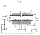
- Fig. 1 shows a drawing representing adhering apparatus 100 for optical disc substrates in a first preferred embodiment according to the present invention.
- Adhering apparatus 100 for optical disc substrates namely, adhering apparatus 100 for optical disc substrates which adheres first optical disc substrate 2 and second optical disc substrate 1 adhered together via adhesive 30 and cures adhesive 30 includes absorbing-and-holding means 20 for absorbing and holding first optical disc substrate 2 serving also as an electrode, absorbing-and-holding means 10 for absorbing and holding second optical disc substrate 1, serving also as another electrode, optical disc substrate moving means 40, distance detecting means 50, velocity controlling means 60, and alternating current voltage applying means 71.
- Absorbing-and-holding means 10 includes chuck means 11 and chuck pawl 12 and is made of a metallic material.
- Chuck pawl 12 supports each inner wall between optical disc substrates 1 and 2 while performing a diameter expanding operation in a center hole between these optical disc substrates 1 and 2 when both of the optical disc substrates 1 and 2 are moved to another position with both of optical disc substrates 1 and 2 overlapped.
- Absorbing-and-holding means 20 is made of a disc-shaped matter made of such a conductive material as stainless.
- Optical disc substrate moving means 40 is means for rising or lowering absorbing-and-adhering means 20 by driving a rise/lower shaft 41 to mutually approach to optical disc substrate 1 and optical disc substrate 2.
- Distance detecting means 50 is means for detecting a distance between optical disc substrate 1 and optical disc substrate 2.
- Velocity controlling section 60 is means for controlling the relative velocity of optical disc substrate 2 to optical disc substrate 1.
- velocity controlling means 60 is means for controlling optical disc substrate moving means 40 in such a manner that the above-described relative velocity at the time point immediately before adhesive 30 applied onto optical disc substrate 2 is brought in contact with optical disc substrate 1 is faster than the relative velocity at the time point immediately after adhesive 30 applied onto optical disc substrate 2 is brought in contact with optical disc substrate 1.
- distance detecting means 50 estimates the time point immediately before adhesive 30 applied onto optical disc substrate 2 is brought in contact with optical disc substrate 1 on the basis of the distance detected by distance detecting means 50.
- Alternating current voltage applying means 70 is the means for applying an alternating current voltage between optical disc substrate 1 and optical disc substrate 2 immediately before adhesive 30 applied on optical disc substrate 2 is brought in contact with optical disc substrate 1 and includes an AC power supply 71, switch 72, and switch controlling means 74.
- Switch controlling means 74 turns on switch 72 when distance detecting means 50 detects that adhesive 30 applied onto optical disc substrate 2 is brought in contact with optical disc substrate 1 and the alternating current voltage is applied between conductive absorbing-and-holding means 10 and 20 so that an alternating current electric field is formed over a space between optical disc substrate 1 and optical disc substrate 2.
- Fig. 2 shows a state in the above-described embodiment in which the distance between optical disc substrates 1 and 2 becomes L2 shorter than L1, switch 72 is turned on, and an alternating current voltage between optical disc substrates 1 and 2 is applied, this alternating current voltage causing adhesive 30 to be tapered.
- Fig. 3 shows a state in the above-described embodiment in which the distance between optical disc substrates 1 and 2 becomes L4 shorter than L2, both of optical disc substrates 1 and 2 approach to each other at a shortest distance, adhesive 30 completely adheres to optical disc 1, switch 72 is turned off, and the application of the alternating current voltage between optical disc substrates 1 and 2 is ended.
- Fig. 4 shows a graph representing a variation of the distance between optical disc substrates 1 and 2 along with an elapse of the time in the above-described embodiment.
- Fig. 5 shows a graph representing a variation pattern of a rising velocity of absorbing-and-holding means 20 along with an elapse of the time in the above-described embodiment.
- the inter-substrate distance indicates L2 and distance detecting means 50 detects inter-substrate distance indicating L2.
- switch control means 74 turns switch 72 on and the alternating current voltage is applied between optical disc substrates 1 and 2.
- adhesive 30 is tapered and velocity controlling means 60 controls optical disc substrate moving means 40 in such a manner that the rising velocity of the absorbing-and-holding means 20 is relatively slowed as shown in Fig. 5 .
- the alternating current voltage is applied, the adhesive 30 is tapered, and the distance between substrates is slowly shortened. Hence, no air bubble occurs in adhesive.
- the power supply voltage developed by alternating current power supply 71 since it is not necessary to increase the power supply voltage developed by alternating current power supply 71 to some degree, no discharge between two sheets of optical disc substrates 1 and 2 occurs.
- the distance between substrates 1 and 2 is slowly shortened.
- the distance between substrates indicates L4 such that optical disc substrates 1 and 2 are mutually approached to each other at the shortest distance.
- adhesive 30 is completely adhered to optical disc substrate 1.
- Distance detecting means 50 detects that the distance between substrates indicates L4.
- velocity controlling means 60 stops the rise of absorbing-and-holding means 20 at time point of t4 or later.
- absorbing-and-holding means 20 is lowered. This lowering velocity is relatively fast so that, at an end stage of one cycle, the absorbing-and-holding means 20 returns to a position shown in Fig. 1 .
- optical disc substrate 2 is finally adhered onto optical disc substrate 1 by means of adhesive 30 in a state shown in Fig. 3 .
- absorbing-and-holding means 20 is raised at a relatively fast speed for a time duration of time point t1 to time point t2 and lowers absorbing-and-holding means 20 relatively quickly, a whole time duration for which two sheets of optical disc substrates 1 and 2 are adhered can be shortened.
- a time during which the alternating current voltage is applied becomes relatively short and the adhesive 30 is not deteriorated.
- the distance between optical disc substrate 1 and optical disc substrate 2 at the time point (time point t2) immediately before adhesive 30 applied onto optical disc substrate 2 is brought in contact with optical disc substrate 1 is set to be equal to or shorter than 5 millimeters and, preferably, equal to or shorter than 2 millimeters.
- a voltage value developed at alternating current power supply 71 is set to a value equal to or lower than a voltage below which no discharge between optical disc substrates 1 and 2 occurs.
- Fig. 6 shows a graph for explaining the operation of a modification of the above-described embodiment, viz., representing a variation pattern of the distance between optical disc substrates 1 and 2 together with the elapse of time.
- Fig. 7 shows a graph representing the variation pattern of the rising velocity of absorbing-and-holding means 20 along with an elapsed time in the modification of the above-described embodiment.
- the rising velocity of absorbing-and-holding means 20 is quickened after time point of t3 in the above-described embodiment and the distance between optical disc substrates 1 and 2 is shortest at time point t4a.
- elapsed time detecting means may be installed for detecting the elapsed time from a predetermined timing in place of distance detecting means 50.
- the elapsed time detecting means estimates that it is a time point (time point t2) immediately before adhesive 30 applied on optical disc substrate 2 is brought in contact with optical disc substrate 1.
- the relative velocity at a time point (time point t2) immediately before adhesive 30 applied onto optical disc substrate 2 is brought in contact with optical disc substrate 1 is equal to or higher than 25 millimeters/ second and, preferably, equal to or higher than 50 millimeters/second.
- the relative velocity at a time point (time point t2) immediately after adhesive 30 applied onto optical disc substrate 2 is brought in contact with optical disc substrate 1 is equal to or lower than 10 millimeters/second and, preferably, equal to or lower than 5 millimeter/second.
- adhesive 30 is applied only onto optical disc substrate 2 and optical disc substrates 1 and 2 are mutually approached to each other.
- optical disc substrates 1 and 2 may be approached to each other with adhesive 30 applied onto both of optical disc substrate 1 and optical disc substrate 2.
- an adhering apparatus for optical disc substrates which adheres first optical disc substrate 2 and second optional disc substrate 1 together via adhesive 30 and cures adhesive 30 includes: optical disc substrate moving means 40 for moving first optical disc substrate 2 and second optical disc substrate plate 1 to approach to each other with the adhesive applied onto the first optical disc substrate 2 and onto the second optical disc substrate 1 while first optical disc substrate 2 is faced against second optical disc substrate 1; velocity controlling means 60 for controlling a relative velocity of second optical disc substrate 1 to first optical disc substrate 2 and controlling the optical disc substrate moving means in such a manner that the relative velocity immediately after and at a time point at which adhesive 30 applied onto the first optical disc substrate 2 is brought in contact with adhesive 30 applied onto second optical disc substrate 1 is slower than that immediately before adhesive 30 applied onto first optical disc substrate 2 is brought in contact with adhesive 30 applied onto second optical disc substrate 1; and alternating current voltage applying means 70 for applying an alternating current voltage between first optional disc substrate 2 and second optical disc substrate 1 immediately before adhesive 30 applied onto the first optical disc substrate 2 is brought in contact with adhesive 30 applied onto the
- the adhering apparatus according to the present invention is applied to the optical disc substrates.
- the present invention is applicable to the plate shaped matter other than the optical disc substrates such as glass plate or lens or applicable to the manufacture of an optical disc in which the plate like matter such as a thin transparent film is used as a light transmission layer.
- the whole time duration to adhere two sheets of optical disc substrates can be shortened.
- no discharge can occur between the two sheets of optical disc substrates and no deterioration in the adhesive can occur.
- the alternating current voltage is applied between optical disc substrates 1 and 2
- the same advantage may be obtained when a direct current voltage may be applied therebetween.
Landscapes
- Engineering & Computer Science (AREA)
- Mechanical Engineering (AREA)
- Manufacturing & Machinery (AREA)
- Chemical & Material Sciences (AREA)
- Chemical Kinetics & Catalysis (AREA)
- General Chemical & Material Sciences (AREA)
- Manufacturing Optical Record Carriers (AREA)
- Adhesives Or Adhesive Processes (AREA)
- Application Of Or Painting With Fluid Materials (AREA)
- Lining Or Joining Of Plastics Or The Like (AREA)
- Coating Apparatus (AREA)
Abstract
Description
- The present invention relates to apparatus and method for adhering two sheets of plate shaped matters such as optical disc substrates.
- As is well known, for example, the following processes are adopted as a conventional method for mutually adhering two sheets of optical disc substrates with an adhesive.
- First, the adhesive is circularly supplied onto an adhering surface of one of the two sheets of optical disc substrates, the one of the two sheets of the optical disc substrates is carried onto a lower disc absorption mechanism of an overlapping mechanism, is absorbed and held thereat, and with an adhering surface of the other of the two sheets of optical disc substrates faced downward, the other of the two sheets of the optical disc substrates is carried onto upper disc absorption mechanism in the overlapping mechanism, and adsorbed and held thereat.
- Thereafter, a voltage is applied between the one optical disc substrate and the other optical disc substrate to make the one optical disc substrate and the other optical disc substrate approach to each other and the two optical disc substrates are overlapped with each other. When a distance between the two optical disc substrates reaches to a set inter-substrate distance, the voltage application is stopped so that the lower disc absorption mechanism and the upper disc absorption mechanism are released from the absorption and holding.
- Then, the two sheets of mutually overlapped optical disc substrates are carried to a spinner. Then, the spinner is rotated at a high speed and the adhesive is widened to a predetermined region. An ultraviolet ray is, then, radiated on the optical disc substrate so as to cure an adhesive layer.
- When the two sheets of optical disc substrates are mutually overlapped with each other via the adhesive , the two optical disc substrates are mutually approached to each other. As a distance between two optical disc substrates becomes shorter, an influence of voltage application becomes so large that a summit portion of the adhesive is tapered and a contact area between the adhesive and the other optical disc substrate becomes very small at an instantaneous time when the adhesive is brought in contact with the other disc substrate. This can mutually overlap the two optical disc substrates without development in air bubbles thereon.
- In the above-described conventional art, in order to shorten a required time of adhering step, a velocity of approaching two sheets of
optical disc substrates - In this case, the increase in the voltage value to be applied causes the electric field to be increased. Hence, the summit portion of the adhesive can be tapered. However, if the two sheets of optical disc substrates mutually approach to each other, a discharge phenomenon occurs between the two sheets of optical disc substrates. This discharge phenomenon causes a partial breakage of a metal reflective film formed on a recording sheet, causes several pits to be damaged, and a reliability of data recording is reduced.
- In addition, after the adhesive is applied over a whole periphery with a predetermined radius of the one optical disc substrate, it is necessary to mutually approach the two sheets of optical disc substrates, to widen a liquid film of the adhesive between an inner peripheral direction and an outer peripheral direction, and to stabilize a liquid film to a degree such that no problem occurs when the two sheets of optical disc substrates are carried. However, a continuous application of voltage causes the adhesive to be deteriorated and a reliability is reduced. The above-described problems could occur in such a plate shaped matter as a glass plate, a lens, or the like other than the optical disc substrates.
- From document
EP 1026214 A2 , it is known an adhering apparatus according to the preamble portion ofclaim 1. - It is an object of the present invention to provide plate shaped matter adhering apparatus and plate shaped matter adhering method which can shorten a whole time duration for which the two sheets of optical disc substrates are adhered together when two shoots of plate shaped matters are mutually approached to each other without development of air bubbles and in which an adhesive in not deteriorated without occurrence in discharge between two sheets of optical disc substrates.
- This object is solved by the
independent claims - Further embodiments of the invention are defined in the dependent claims.
-
-
Fig. 1 is a schematic drawing representing anadhering apparatus 10 for optical disc substrates in a first preferred embodiment according to the present invention. -
Fig. 2 is a schematic drawing of the first embodiment representing a state in which a distance betweenoptical disc substrates switch 72 is turned on, a voltage betweenoptical disc substrates -
Fig. 3 is a schematic drawing of the first embodiment representing a state in which the distance betweenoptical disc substrates optical disc substrates optical disc 2,switch 72 is turned off, and the application of the voltage is ended at a space betweenoptical disc substrates -
Fig. 4 is a graph representing a pattern in which the distance betweenoptical disc substrates -
Fig. 5 is a graph representing a pattern in which a rising velocity of absorbing-and-holding means 20 is varied as the time is elapsed. -
Fig. 6 is a graph representing a variation in the distance betweenoptical disc substrates -
Fig. 7 is a graph representing a variation in a rising velocity of absorbing-and-holding means 20 as the time is elapsed in the modification of the above-described embodiment. - Reference will hereinafter be made to the drawings in order to facilitate a better understanding of the present invention.
-
Fig. 1 shows a drawing representing adheringapparatus 100 for optical disc substrates in a first preferred embodiment according to the present invention. - Adhering
apparatus 100 for optical disc substrates, namely, adheringapparatus 100 for optical disc substrates which adheres firstoptical disc substrate 2 and secondoptical disc substrate 1 adhered together via adhesive 30 and cures adhesive 30 includes absorbing-and-holding means 20 for absorbing and holding firstoptical disc substrate 2 serving also as an electrode, absorbing-and-holding means 10 for absorbing and holding secondoptical disc substrate 1, serving also as another electrode, optical disc substrate moving means 40, distance detecting means 50, velocity controllingmeans 60, and alternating current voltage applying means 71. Absorbing-and-holding means 10 includes chuck means 11 andchuck pawl 12 and is made of a metallic material. - Chuck
pawl 12 supports each inner wall betweenoptical disc substrates optical disc substrates optical disc substrates optical disc substrates - Absorbing-and-holding means 20 is made of a disc-shaped matter made of such a conductive material as stainless.
- It is noted that, in
Fig. 1 , specific absorbing means such as a vacuum compressor is omitted inFig. 1 in the absorbing-and-holding means 10 and 20. - Optical disc substrate moving means 40 is means for rising or lowering absorbing-and-adhering means 20 by driving a rise/
lower shaft 41 to mutually approach tooptical disc substrate 1 andoptical disc substrate 2. - Distance detecting means 50 is means for detecting a distance between
optical disc substrate 1 andoptical disc substrate 2. -
Velocity controlling section 60 is means for controlling the relative velocity ofoptical disc substrate 2 tooptical disc substrate 1. In addition, velocity controllingmeans 60 is means for controlling optical disc substrate moving means 40 in such a manner that the above-described relative velocity at the time point immediately before adhesive 30 applied ontooptical disc substrate 2 is brought in contact withoptical disc substrate 1 is faster than the relative velocity at the time point immediately after adhesive 30 applied ontooptical disc substrate 2 is brought in contact withoptical disc substrate 1. - It is noted that, in this embodiment, distance detecting means 50 estimates the time point immediately before adhesive 30 applied onto
optical disc substrate 2 is brought in contact withoptical disc substrate 1 on the basis of the distance detected by distance detecting means 50. - Alternating current voltage applying means 70 is the means for applying an alternating current voltage between
optical disc substrate 1 andoptical disc substrate 2 immediately before adhesive 30 applied onoptical disc substrate 2 is brought in contact withoptical disc substrate 1 and includes anAC power supply 71,switch 72, and switch controllingmeans 74. - Switch controlling means 74 turns on
switch 72 when distance detecting means 50 detects that adhesive 30 applied ontooptical disc substrate 2 is brought in contact withoptical disc substrate 1 and the alternating current voltage is applied between conductive absorbing-and-holding means 10 and 20 so that an alternating current electric field is formed over a space betweenoptical disc substrate 1 andoptical disc substrate 2. - Next, an operation of adhering
apparatus 100 foroptical disc substrates -
Fig. 2 shows a state in the above-described embodiment in which the distance betweenoptical disc substrates switch 72 is turned on, and an alternating current voltage betweenoptical disc substrates -
Fig. 3 shows a state in the above-described embodiment in which the distance betweenoptical disc substrates optical disc substrates optical disc 1,switch 72 is turned off, and the application of the alternating current voltage betweenoptical disc substrates -
Fig. 4 shows a graph representing a variation of the distance betweenoptical disc substrates -
Fig. 5 shows a graph representing a variation pattern of a rising velocity of absorbing-and-holding means 20 along with an elapse of the time in the above-described embodiment. - First, at a time point of t1 shown in
Fig. 4 , the distance between substrates is L1,switch 72 is turned off, and no alternating current voltage is applied betweenoptical disc substrates Fig. 5 . The distance betweenoptical disc substrates - Thereafter, at a time point of t2, the inter-substrate distance indicates L2 and distance detecting means 50 detects inter-substrate distance indicating L2. Upon receipt of inter-substrate distance information from distance detecting means 50, switch control means 74 turns switch 72 on and the alternating current voltage is applied between
optical disc substrates Fig. 2 , adhesive 30 is tapered and velocity controlling means 60 controls optical disc substrate moving means 40 in such a manner that the rising velocity of the absorbing-and-holding means 20 is relatively slowed as shown inFig. 5 . - Then, at a time point of t3, the distance between
optical disc substrates substrates section 74 turns offswitch 72 and the application of the alternating current voltage is ended. - As described above, at time point of t2, the alternating current voltage is applied, the adhesive 30 is tapered, and the distance between substrates is slowly shortened. Hence, no air bubble occurs in adhesive. In addition, since it is not necessary to increase the power supply voltage developed by alternating
current power supply 71 to some degree, no discharge between two sheets ofoptical disc substrates - After time point of t3, the distance between
substrates optical disc substrates Fig. 3 , adhesive 30 is completely adhered tooptical disc substrate 1. Distance detectingmeans 50 detects that the distance between substrates indicates L4. Whendistance detecting means 50 detects that the distance indicates L4, velocity controlling means 60 stops the rise of absorbing-and-holding means 20 at time point of t4 or later. Next, absorbing-and-holding means 20 is lowered. This lowering velocity is relatively fast so that, at an end stage of one cycle, the absorbing-and-holding means 20 returns to a position shown inFig. 1 . At this time,optical disc substrate 2 is finally adhered ontooptical disc substrate 1 by means of adhesive 30 in a state shown inFig. 3 . - As described above, in the above-described embodiment, since absorbing-and-holding means 20 is raised at a relatively fast speed for a time duration of time point t1 to time point t2 and lowers absorbing-and-holding means 20 relatively quickly, a whole time duration for which two sheets of
optical disc substrates Fig. 4 , a time during which the alternating current voltage is applied becomes relatively short and the adhesive 30 is not deteriorated. - In addition, in the above-described embodiment, the distance between
optical disc substrate 1 andoptical disc substrate 2 at the time point (time point t2) immediately before adhesive 30 applied ontooptical disc substrate 2 is brought in contact withoptical disc substrate 1 is set to be equal to or shorter than 5 millimeters and, preferably, equal to or shorter than 2 millimeters. - In addition, as a contact area when a liquid film of adhesive 30 formed on one
optical disc substrates other disc substrate current power supply 71 is set to a value equal to or lower than a voltage below which no discharge betweenoptical disc substrates -
Fig. 6 shows a graph for explaining the operation of a modification of the above-described embodiment, viz., representing a variation pattern of the distance betweenoptical disc substrates -
Fig. 7 shows a graph representing the variation pattern of the rising velocity of absorbing-and-holding means 20 along with an elapsed time in the modification of the above-described embodiment. - In the modification shown in
Figs. 6 and 7 , the rising velocity of absorbing-and-holding means 20 is quickened after time point of t3 in the above-described embodiment and the distance betweenoptical disc substrates - In this modification, the same advantages as those in the above-described embodiment shown in
Figs. 4 and 5 can be obtained. It is noted that, in this modification, if the velocity after time point t4a is made equal to that in the embodiment shown inFigs. 4 and 5 , the whole adhering time duration can be shortened than that in the case of the embodiment shown inFigs. 4 and 5 . - It is noted that, in the above-described embodiment, elapsed time detecting means may be installed for detecting the elapsed time from a predetermined timing in place of
distance detecting means 50. The elapsed time detecting means estimates that it is a time point (time point t2) immediately before adhesive 30 applied onoptical disc substrate 2 is brought in contact withoptical disc substrate 1. In this case, the relative velocity at a time point (time point t2) immediately before adhesive 30 applied ontooptical disc substrate 2 is brought in contact withoptical disc substrate 1 is equal to or higher than 25 millimeters/ second and, preferably, equal to or higher than 50 millimeters/second. In addition, in the above-described case, the relative velocity at a time point (time point t2) immediately after adhesive 30 applied ontooptical disc substrate 2 is brought in contact withoptical disc substrate 1 is equal to or lower than 10 millimeters/second and, preferably, equal to or lower than 5 millimeter/second. - Furthermore, in the above-described embodiment, adhesive 30 is applied only onto
optical disc substrate 2 andoptical disc substrates optical disc substrates optical disc substrate 1 andoptical disc substrate 2. - That is to say, in this case, an adhering apparatus for optical disc substrates which adheres first optical disc substrate 2 and second optional disc substrate 1 together via adhesive 30 and cures adhesive 30 includes: optical disc substrate moving means 40 for moving first optical disc substrate 2 and second optical disc substrate plate 1 to approach to each other with the adhesive applied onto the first optical disc substrate 2 and onto the second optical disc substrate 1 while first optical disc substrate 2 is faced against second optical disc substrate 1; velocity controlling means 60 for controlling a relative velocity of second optical disc substrate 1 to first optical disc substrate 2 and controlling the optical disc substrate moving means in such a manner that the relative velocity immediately after and at a time point at which adhesive 30 applied onto the first optical disc substrate 2 is brought in contact with adhesive 30 applied onto second optical disc substrate 1 is slower than that immediately before adhesive 30 applied onto first optical disc substrate 2 is brought in contact with adhesive 30 applied onto second optical disc substrate 1; and alternating current voltage applying means 70 for applying an alternating current voltage between first optional disc substrate 2 and second optical disc substrate 1 immediately before adhesive 30 applied onto the first optical disc substrate 2 is brought in contact with adhesive 30 applied onto the second optical disc substrate 1.
- In the above-described case, in a process in which the liquid film of
adhesive 30 ofoptical disc substrate 2 is brought in contact with the liquid film ofadhesive 30 ofoptical disc substrate 1, as a space betweenoptical disc substrates optical disc substrates optical disc substrate 1, the realization can be achieved. The same advantages as described in the embodiment can be obtained. - In each of the above-described embodiments, the adhering apparatus according to the present invention is applied to the optical disc substrates. However, the present invention is applicable to the plate shaped matter other than the optical disc substrates such as glass plate or lens or applicable to the manufacture of an optical disc in which the plate like matter such as a thin transparent film is used as a light transmission layer.
- According to the present invention, in a case where two sheets of plate shaped matters are mutually approached to each other without development of air bubbles on the adhesive after the adhesive is applied over the whole periphery of the plate shaped matters, the whole time duration to adhere two sheets of optical disc substrates can be shortened. In addition, no discharge can occur between the two sheets of optical disc substrates and no deterioration in the adhesive can occur. It is noted that, although, in each embodiment, the alternating current voltage is applied between
optical disc substrates
Claims (18)
- An adhering apparatus (100) for adhering first and second plate-shaped objects (1, 2) together via an adhesive (30) and curing the adhesive (30), the adhering apparatus (100) comprising:plate moving means (40) for moving the first plate-shaped object (2) and the second plate-shaped object (1) to approach to each other with the adhesive (30) applied onto the first plate-shaped object (2) while the first plate-shaped object (2) is faced against the second plate-shaped object (1);velocity controlling means (60) for controlling a relative approaching velocity between the first and second plate-shaped objects (1, 2); andvoltage applying means (70) for applying voltage between the first plate-shaped object (2) and the second plate-shaped object (1) before a contact time point at which the adhesive (30) applied onto the first plate-shaped object (2) is brought in contact with the second plate-shaped object (1);characterized in that
the velocity controlling means (60) is configured to control the plate moving means (40) in such a manner that the relative approaching velocity immediately after and at the contact time point at which the adhesive applied on the first plate-shaped object (2) is brought in contact with the second plate-shaped object (1) is slower than the relative approaching velocity at a time point (t2) immediately before the contact time point at which the adhesive applied onto the first plate-shaped object (2) is brought in contact with the second plate-shaped object (1). - An adhering apparatus (100) as claimed in claim 1, wherein the velocity controlling means (60) is configured to make the relative approaching velocity at the contact time point at which the adhesive applied onto the first plate-shaped object (2) is brought in contact with the second plate-shaped object (1), slower than the relative approaching velocity at the time point (t2) immediately before the contact time point, and to hold the relative approaching velocity immediately after the contact time point, slower than the relative approaching velocity at the time point (t2) immediately before the contact time point.
- An adhering apparatus (100) as claimed in claim 1, wherein the voltage applying means (70) is configured to start the application of the voltage between the first plate-shaped object (2) and the second plate-shaped object (1) at the time point (t2) immediately before the contact time point.
- An adhering apparatus (100) as claimed in claim 1, wherein the velocity controlling means (60) controls the plate moving means (40) to move the first plate-shaped object (2) and the second plate-shaped object (1) to approach to each other at a quick speed from a first time point (t1) to the time point (t2) immediately before the contact time point, and the velocity controlling means (60) further controls the plate moving means (40) in such a manner that the relative approaching velocity is controlled at a slow speed slower than the quick speed at the contact time point and immediately after the contact time point.
- An adhering apparatus (100) as claimed in claim 4, wherein the velocity controlling means (60) holds the relative approaching velocity between the first and second plate-shaped objects (1, 2) at the slow speed, from the time point (t2) immediately before the contact time point until a third time point (t3) after the contact time point.
- An adhering apparatus (100) as claimed in claim 1, wherein the adhering apparatus further comprises a distance detecting means (50) for detecting a distance (L) between the first plate-shaped object (2) and the second plate-shaped object (1) and estimating the time point (t2) immediately before the contact time point at which the adhesive applied onto the first plate-shaped object (2) is brought in contact with the second plate-shaped object (1) on the basis of the distance (L) detected by the distance detecting means.
- An adhering apparatus (100) as claimed in claim 6, wherein the distance (L2) between the first plate-shaped object (2) and the second plate-shaped object (1) at the time point (t2) immediately before the contact between the first and second plate-shaped objects (1, 2) through the adhesive (30) is equal to or shorter than 2 mm or is equal to or shorter than 5 mm.
- An adhering apparatus (100) as claimed in claim 1, wherein the adhering apparatus further comprises a time elapsed detecting means for detecting a time elapsed from a predetermined timing and estimates the timing point (t2) immediately before the adhesive applied onto the first plate-shaped object (2) is brought in contact with the second plate-shaped object (1) on the basis of the time detected by the time elapsed detecting means.
- An adhering apparatus (100) as claimed in claim 1, wherein the velocity controlling means (60) is configured to control the plate moving means (40) in such a manner that the relative approaching velocity between the first and second plate-shaped objects (1, 2) at the time point (t2) immediately before the contact time point the adhesive (30) applied onto the first plate-shaped object (2) is brought in contact with the second plate-shaped object (1) is equal to or higher than 25 millimeter/second or equal to or higher than 50 millimeter/second.
- An adhering apparatus (100) as claimed in claim 1, wherein the velocity controlling means (60) is configured to set the relative approaching velocity between the first and second plate-shaped objects (1, 2) equal to or lower than 5 millimeter/second or equal to or lower than 10 millimeter/second at the time point (t2) immediately before the contact time point.
- An adhering apparatus (100) for adhering first and second plate-shaped objects (1, 2) together via an adhesive (30) and curing the adhesive (30), the adhering apparatus (100) comprising:plate moving means (40) for moving the first plate-shaped object (2) and the second plate-shaped object (1) to approach to each other with the adhesive (30) applied onto the first plate-shaped object (2) and onto the second plate-shaped object (1) while the first plate-shaped object (2) is faced against the second plate-shaped object (1);velocity controlling means (60) for controlling a relative approaching velocity between the first and second plate-shaped objects (1, 2); andvoltage applying means (70) for applying voltage between the first plate-shaped object (2) and the second plate-shaped object (1) before a contact time point at which the adhesive (30) applied onto the first plate-shaped object (2) is brought in contact with the adhesive (30) applied onto the second plate-shaped object (1);characterized in that
the velocity controlling means (60) is configured to control the plate moving means (40) in such a manner that the relative approaching velocity immediately after and at the contact time point at which the adhesive applied on the first plate-shaped object (2) is brought in contact with adhesive (30) applied onto the second plate-shaped object (1) is slower than the relative approaching velocity at a time point (t2) immediately before the contact time point at which the adhesive (30) applied onto the first plate-shaped object (2) is brought in contact with the adhesive (30) applied onto the second plate-shaped object (1). - An adhering apparatus (100) as claimed in claim 11, wherein the velocity controlling means (60) is configured to make the relative approaching velocity between the first and second plate-shaped objects (1, 2) at the contact time point and immediately after the contact time point, slower than the relative approaching velocity at the time point (t2) immediately before the contact time point.
- An adhering apparatus (100) as claimed in any one of claims 1 to 12, wherein the voltage applying means (70) is configured to terminate the application of the voltage after the contact time point.
- An adhering method for adhering first and second plate-shaped objects (1, 2) together via an adhesive (30) and curing the adhesive, the adhering method comprising:a plate-shaped object moving step for moving the first plate-shaped object (2) and the second plate-shaped object (1) toward each other with the adhesive (30) applied onto the first plate-shaped object (2) while the first plate-shaped object (2) is faced against the second plate-shaped object (1);a velocity controlling step for controlling a relative approaching velocity between the first and second plate-shaped objects (1, 2); anda voltage applying step for applying voltage between the first plate-shaped object (2) and the second plate-shaped object (1) before a contact time point at which the adhesive (30) applied onto the first plate-shaped object (2) is brought in contact with the second plate-shaped object (1);characterized in that
the relative approaching velocity immediately after and at the contact time point at which the adhesive applied on the first plate-shaped object (2) is brought in contact with the second plate-shaped object (1) is slower than the relative approaching velocity at a time point (t2) immediately before the contact time point at which the adhesive (30) applied onto the first plate-shaped object (2) is brought in contact with the second plate-shaped object (1). - An adhering method as claimed in claim 14, wherein the first and second plate-shaped objects (1, 2) are moved to approach to each other at a quick speed from a first time point (t1) to the time point (t2) immediately before the contact time point; and the relative approaching velocity at the contact time point and immediately after the contact time point is slower than the quick speed.
- An adhering method as claimed in claim 14, wherein the time point (t2) immediately before the contact between the first and second plate-shaped objects through the adhesive (30) is determined by monitoring an approaching condition which is one of the distance (L) between the first and second plate-shaped objects and an elapsed time from a predetermined timing.
- An adhering method for adhering first and second plate-shaped objects (1, 2) together via an adhesive (30) and curing the adhesive, the adhering method comprising:a plate-shaped object moving step for moving the first plate-shaped object (2) and the second plate-shaped object (1) toward each other with the adhesive (30) applied onto the first plate-shaped object (2) and onto the second plate-shaped object (1) while the first plate-shaped object (2) is faced against the second plate-shaped object (1);a velocity controlling step for controlling a relative approaching velocity between the first and second plate-shaped objects (1, 2); anda voltage applying step for applying voltage between the first plate-shaped object (2) and the second plate-shaped object (1) before a contact time point at which the adhesive (30) applied onto the first plate-shaped object (2) is brought in contact with the second plate-shaped object (1);characterized in that
the relative approaching velocity immediately after and at the contact time point at which the adhesive (30) applied on the first plate-shaped object (2) is brought in contact with the adhesive (30) applied onto the second plate-shaped object (1) is slower than the relative approaching velocity at a time point (t2) immediately before the contact time point at which the adhesive applied onto the first plate-shaped object (2) is brought in contact with the adhesive applied onto the second plate-shaped object (1). - An adhering method as claimed in one of claims 14-17, wherein the application of the voltage is stopped when the first and second plate-shaped objects (1, 2) are brought into contact through the adhesive (30).
Applications Claiming Priority (3)
| Application Number | Priority Date | Filing Date | Title |
|---|---|---|---|
| JP2001049513A JP3678349B2 (en) | 2001-02-26 | 2001-02-26 | Plate-shaped object laminating apparatus and plate-shaped object laminating method |
| JP2001049513 | 2001-02-26 | ||
| PCT/JP2002/001080 WO2002068554A1 (en) | 2001-02-26 | 2002-02-08 | Apparatus for bonding plate-shaped objects together and method for bonding plate-shaped objects together |
Publications (3)
| Publication Number | Publication Date |
|---|---|
| EP1375620A1 EP1375620A1 (en) | 2004-01-02 |
| EP1375620A4 EP1375620A4 (en) | 2008-01-23 |
| EP1375620B1 true EP1375620B1 (en) | 2011-11-30 |
Family
ID=18910606
Family Applications (1)
| Application Number | Title | Priority Date | Filing Date |
|---|---|---|---|
| EP02712295A Expired - Lifetime EP1375620B1 (en) | 2001-02-26 | 2002-02-08 | Apparatus for bonding plate-shaped objects together and method for bonding plate-shaped objects together |
Country Status (8)
| Country | Link |
|---|---|
| US (1) | US6773525B2 (en) |
| EP (1) | EP1375620B1 (en) |
| JP (1) | JP3678349B2 (en) |
| KR (1) | KR100473122B1 (en) |
| CN (1) | CN1315962C (en) |
| DE (1) | DE02712295T1 (en) |
| TW (1) | TW591655B (en) |
| WO (1) | WO2002068554A1 (en) |
Families Citing this family (6)
| Publication number | Priority date | Publication date | Assignee | Title |
|---|---|---|---|---|
| US7479202B1 (en) * | 2005-06-28 | 2009-01-20 | Anwell Precision Technology (Hk) Limited | Bubble-free techniques for bonding substrates |
| US8127820B1 (en) * | 2005-06-28 | 2012-03-06 | Anwell Technologies Limited | System for producing optical recording medium |
| EP2006362A4 (en) | 2006-03-30 | 2010-11-10 | Mitsui Shipbuilding Eng | Process for producing gas hydrate pellet |
| JP5345239B1 (en) * | 2012-11-13 | 2013-11-20 | オリジン電気株式会社 | Joining member manufacturing method and apparatus |
| US9644946B1 (en) | 2015-07-09 | 2017-05-09 | Mark LeBlanc | System and method for photographic inspection and documentation of post-tensioned concrete tendon terminations |
| WO2022230199A1 (en) | 2021-04-30 | 2022-11-03 | オリンパス株式会社 | Substrate bonding apparatus and substrate bonding method |
Family Cites Families (9)
| Publication number | Priority date | Publication date | Assignee | Title |
|---|---|---|---|---|
| US4397175A (en) * | 1981-04-24 | 1983-08-09 | The Gleason Works | Apparatus for controlling the movement of a reciprocatory hydraulically driven element |
| IT1222998B (en) * | 1986-11-04 | 1990-09-12 | Dieffenbacher Gmbh Maschf | QUICK STROKE HYDRAULIC PRESS |
| SU1451045A1 (en) * | 1987-05-15 | 1989-01-15 | Минское Экспериментально-Конструкторское Технологическое Бюро Кожгалантерейной И Фурнитурной Промышленности | Press for h.f. welding of articles from thermoplastic materials |
| US5080736A (en) * | 1989-05-26 | 1992-01-14 | Matsui Manufacturing Co., Ltd. | System for mounting a hub to an optical disk and a method therefor |
| JPH07182697A (en) * | 1993-12-15 | 1995-07-21 | Nikon Corp | Method of manufacturing optical recording medium |
| JP3853908B2 (en) * | 1997-03-31 | 2006-12-06 | 株式会社小松製作所 | Multi-point servo press controller |
| JP3515877B2 (en) | 1997-05-09 | 2004-04-05 | 株式会社リコー | Laminated optical disk and method of manufacturing the same |
| JP2000198000A (en) * | 1998-12-28 | 2000-07-18 | Komatsu Ltd | Press molding apparatus and molding method |
| TW459225B (en) | 1999-02-01 | 2001-10-11 | Origin Electric | Bonding system and method |
-
2001
- 2001-02-26 JP JP2001049513A patent/JP3678349B2/en not_active Expired - Lifetime
-
2002
- 2002-02-08 CN CNB028003977A patent/CN1315962C/en not_active Expired - Lifetime
- 2002-02-08 DE DE0001375620T patent/DE02712295T1/en active Pending
- 2002-02-08 WO PCT/JP2002/001080 patent/WO2002068554A1/en not_active Ceased
- 2002-02-08 EP EP02712295A patent/EP1375620B1/en not_active Expired - Lifetime
- 2002-02-08 KR KR10-2002-7014340A patent/KR100473122B1/en not_active Expired - Lifetime
- 2002-02-08 US US10/239,564 patent/US6773525B2/en not_active Expired - Lifetime
- 2002-02-22 TW TW091103195A patent/TW591655B/en not_active IP Right Cessation
Also Published As
| Publication number | Publication date |
|---|---|
| TW591655B (en) | 2004-06-11 |
| KR100473122B1 (en) | 2005-03-10 |
| CN1457352A (en) | 2003-11-19 |
| EP1375620A4 (en) | 2008-01-23 |
| US20030075267A1 (en) | 2003-04-24 |
| CN1315962C (en) | 2007-05-16 |
| EP1375620A1 (en) | 2004-01-02 |
| KR20020093951A (en) | 2002-12-16 |
| JP2002251804A (en) | 2002-09-06 |
| WO2002068554A1 (en) | 2002-09-06 |
| JP3678349B2 (en) | 2005-08-03 |
| DE02712295T1 (en) | 2004-07-08 |
| US6773525B2 (en) | 2004-08-10 |
Similar Documents
| Publication | Publication Date | Title |
|---|---|---|
| KR100469217B1 (en) | Method of manufacturing disk substrate, and method and device for manufacturing optical disk | |
| EP1026214B1 (en) | Bonding system and method | |
| JP3986383B2 (en) | Manufacturing method and manufacturing apparatus of plate-like body | |
| EP1026677B1 (en) | Manufacturing method and apparatus for optical disc | |
| US6773525B2 (en) | Plate shaped matter adhering apparatus and method | |
| EP1656999B1 (en) | Method for supplying liquid material | |
| JP2000036134A (en) | Optical disc bonding method and apparatus | |
| US6080249A (en) | Method for adhering a member and apparatus for adhering a member | |
| US20080283192A1 (en) | Method and apparatus for bonding optical disc substrates together, and method for supplying liquid material | |
| JP3515877B2 (en) | Laminated optical disk and method of manufacturing the same | |
| JP4179502B2 (en) | Method and apparatus for forming coating film | |
| JP3194280B2 (en) | Optical disc and method of manufacturing the same | |
| KR102855558B1 (en) | Method for bonding two substrates | |
| JP3469137B2 (en) | Optical disc bonding method | |
| JP2004342273A (en) | Medium bonding method and apparatus | |
| JP3343137B2 (en) | Adhesive coating device for optical disks | |
| JPH04212958A (en) | Pellicle frame attaching method | |
| JPH11283288A (en) | Disc substrate bonding method and apparatus therefor | |
| CN115216724A (en) | Sputtering pretreatment method | |
| JP2009245550A (en) | Apparatus and method for manufacturing optical disk | |
| JPH07182697A (en) | Method of manufacturing optical recording medium | |
| JPH07130017A (en) | Magneto-optical recording medium manufacturing method and magneto-optical recording medium | |
| JP2006218576A (en) | Lens sticking method | |
| JP2000315719A (en) | Tape peeling method | |
| JP2003231866A (en) | Object joining method, joining apparatus, and disc manufacturing apparatus |
Legal Events
| Date | Code | Title | Description |
|---|---|---|---|
| PUAI | Public reference made under article 153(3) epc to a published international application that has entered the european phase |
Free format text: ORIGINAL CODE: 0009012 |
|
| 17P | Request for examination filed |
Effective date: 20021001 |
|
| AK | Designated contracting states |
Kind code of ref document: A1 Designated state(s): AT BE CH CY DE DK ES FI FR GB GR IE IT LI LU MC NL PT SE TR |
|
| R17P | Request for examination filed (corrected) |
Effective date: 20021001 |
|
| DET | De: translation of patent claims | ||
| A4 | Supplementary search report drawn up and despatched |
Effective date: 20071220 |
|
| 17Q | First examination report despatched |
Effective date: 20080402 |
|
| GRAP | Despatch of communication of intention to grant a patent |
Free format text: ORIGINAL CODE: EPIDOSNIGR1 |
|
| RBV | Designated contracting states (corrected) |
Designated state(s): DE IE |
|
| GRAS | Grant fee paid |
Free format text: ORIGINAL CODE: EPIDOSNIGR3 |
|
| GRAA | (expected) grant |
Free format text: ORIGINAL CODE: 0009210 |
|
| AK | Designated contracting states |
Kind code of ref document: B1 Designated state(s): DE IE |
|
| REG | Reference to a national code |
Ref country code: IE Ref legal event code: FG4D |
|
| REG | Reference to a national code |
Ref country code: DE Ref legal event code: R096 Ref document number: 60241655 Country of ref document: DE Effective date: 20120119 |
|
| PLBE | No opposition filed within time limit |
Free format text: ORIGINAL CODE: 0009261 |
|
| STAA | Information on the status of an ep patent application or granted ep patent |
Free format text: STATUS: NO OPPOSITION FILED WITHIN TIME LIMIT |
|
| 26N | No opposition filed |
Effective date: 20120831 |
|
| REG | Reference to a national code |
Ref country code: IE Ref legal event code: MM4A |
|
| REG | Reference to a national code |
Ref country code: DE Ref legal event code: R097 Ref document number: 60241655 Country of ref document: DE Effective date: 20120831 |
|
| PG25 | Lapsed in a contracting state [announced via postgrant information from national office to epo] |
Ref country code: IE Free format text: LAPSE BECAUSE OF NON-PAYMENT OF DUE FEES Effective date: 20120208 |
|
| PGFP | Annual fee paid to national office [announced via postgrant information from national office to epo] |
Ref country code: DE Payment date: 20140225 Year of fee payment: 13 |
|
| REG | Reference to a national code |
Ref country code: DE Ref legal event code: R119 Ref document number: 60241655 Country of ref document: DE |
|
| PG25 | Lapsed in a contracting state [announced via postgrant information from national office to epo] |
Ref country code: DE Free format text: LAPSE BECAUSE OF NON-PAYMENT OF DUE FEES Effective date: 20150901 |