EP1375366A1 - Packaging bag, and method of and apparatus for manufacturing the same - Google Patents
Packaging bag, and method of and apparatus for manufacturing the same Download PDFInfo
- Publication number
- EP1375366A1 EP1375366A1 EP03011985A EP03011985A EP1375366A1 EP 1375366 A1 EP1375366 A1 EP 1375366A1 EP 03011985 A EP03011985 A EP 03011985A EP 03011985 A EP03011985 A EP 03011985A EP 1375366 A1 EP1375366 A1 EP 1375366A1
- Authority
- EP
- European Patent Office
- Prior art keywords
- bag
- ply
- tubular film
- film material
- edge
- Prior art date
- Legal status (The legal status is an assumption and is not a legal conclusion. Google has not performed a legal analysis and makes no representation as to the accuracy of the status listed.)
- Withdrawn
Links
- 238000004806 packaging method and process Methods 0.000 title claims abstract description 26
- 238000000034 method Methods 0.000 title claims description 15
- 238000004519 manufacturing process Methods 0.000 title claims description 14
- 239000000463 material Substances 0.000 claims description 57
- 238000007789 sealing Methods 0.000 claims description 22
- 230000015572 biosynthetic process Effects 0.000 claims description 6
- 238000011144 upstream manufacturing Methods 0.000 claims description 4
- 230000001747 exhibiting effect Effects 0.000 claims description 2
- 239000002985 plastic film Substances 0.000 claims 1
- 229920006255 plastic film Polymers 0.000 claims 1
- 238000000926 separation method Methods 0.000 claims 1
- 239000010410 layer Substances 0.000 description 10
- 210000005069 ears Anatomy 0.000 description 5
- 230000008569 process Effects 0.000 description 5
- 229920003023 plastic Polymers 0.000 description 3
- 239000004033 plastic Substances 0.000 description 3
- 230000009471 action Effects 0.000 description 2
- 238000001125 extrusion Methods 0.000 description 2
- 230000000977 initiatory effect Effects 0.000 description 2
- 238000009966 trimming Methods 0.000 description 2
- 230000004888 barrier function Effects 0.000 description 1
- 230000005540 biological transmission Effects 0.000 description 1
- 238000005520 cutting process Methods 0.000 description 1
- 230000000694 effects Effects 0.000 description 1
- 230000007246 mechanism Effects 0.000 description 1
- 230000004048 modification Effects 0.000 description 1
- 238000012986 modification Methods 0.000 description 1
- 230000000149 penetrating effect Effects 0.000 description 1
- 230000002787 reinforcement Effects 0.000 description 1
- 238000005096 rolling process Methods 0.000 description 1
- 229920006300 shrink film Polymers 0.000 description 1
- 239000002356 single layer Substances 0.000 description 1
- 239000007858 starting material Substances 0.000 description 1
- 238000003860 storage Methods 0.000 description 1
- 230000001360 synchronised effect Effects 0.000 description 1
- 230000003313 weakening effect Effects 0.000 description 1
- 230000037303 wrinkles Effects 0.000 description 1
Images


Classifications
-
- B—PERFORMING OPERATIONS; TRANSPORTING
- B65—CONVEYING; PACKING; STORING; HANDLING THIN OR FILAMENTARY MATERIAL
- B65B—MACHINES, APPARATUS OR DEVICES FOR, OR METHODS OF, PACKAGING ARTICLES OR MATERIALS; UNPACKING
- B65B9/00—Enclosing successive articles, or quantities of material, e.g. liquids or semiliquids, in flat, folded, or tubular webs of flexible sheet material; Subdividing filled flexible tubes to form packages
- B65B9/06—Enclosing successive articles, or quantities of material, in a longitudinally-folded web, or in a web folded into a tube about the articles or quantities of material placed upon it
- B65B9/08—Enclosing successive articles, or quantities of material, in a longitudinally-folded web, or in a web folded into a tube about the articles or quantities of material placed upon it in a web folded and sealed transversely to form pockets which are subsequently filled and then closed by sealing
- B65B9/093—Enclosing successive articles, or quantities of material, in a longitudinally-folded web, or in a web folded into a tube about the articles or quantities of material placed upon it in a web folded and sealed transversely to form pockets which are subsequently filled and then closed by sealing the web having intermittent motion
-
- B—PERFORMING OPERATIONS; TRANSPORTING
- B31—MAKING ARTICLES OF PAPER, CARDBOARD OR MATERIAL WORKED IN A MANNER ANALOGOUS TO PAPER; WORKING PAPER, CARDBOARD OR MATERIAL WORKED IN A MANNER ANALOGOUS TO PAPER
- B31B—MAKING CONTAINERS OF PAPER, CARDBOARD OR MATERIAL WORKED IN A MANNER ANALOGOUS TO PAPER
- B31B70/00—Making flexible containers, e.g. envelopes or bags
-
- B—PERFORMING OPERATIONS; TRANSPORTING
- B65—CONVEYING; PACKING; STORING; HANDLING THIN OR FILAMENTARY MATERIAL
- B65D—CONTAINERS FOR STORAGE OR TRANSPORT OF ARTICLES OR MATERIALS, e.g. BAGS, BARRELS, BOTTLES, BOXES, CANS, CARTONS, CRATES, DRUMS, JARS, TANKS, HOPPERS, FORWARDING CONTAINERS; ACCESSORIES, CLOSURES, OR FITTINGS THEREFOR; PACKAGING ELEMENTS; PACKAGES
- B65D33/00—Details of, or accessories for, sacks or bags
- B65D33/007—Details of, or accessories for, sacks or bags for facilitating the separation of the two walls, e.g. walls of inequal height, tabs; for maintaining the mouth of the sack or bag open
-
- B—PERFORMING OPERATIONS; TRANSPORTING
- B65—CONVEYING; PACKING; STORING; HANDLING THIN OR FILAMENTARY MATERIAL
- B65D—CONTAINERS FOR STORAGE OR TRANSPORT OF ARTICLES OR MATERIALS, e.g. BAGS, BARRELS, BOTTLES, BOXES, CANS, CARTONS, CRATES, DRUMS, JARS, TANKS, HOPPERS, FORWARDING CONTAINERS; ACCESSORIES, CLOSURES, OR FITTINGS THEREFOR; PACKAGING ELEMENTS; PACKAGES
- B65D75/00—Packages comprising articles or materials partially or wholly enclosed in strips, sheets, blanks, tubes or webs of flexible sheet material, e.g. in folded wrappers
- B65D75/002—Packages comprising articles or materials partially or wholly enclosed in strips, sheets, blanks, tubes or webs of flexible sheet material, e.g. in folded wrappers in shrink films
-
- B—PERFORMING OPERATIONS; TRANSPORTING
- B65—CONVEYING; PACKING; STORING; HANDLING THIN OR FILAMENTARY MATERIAL
- B65D—CONTAINERS FOR STORAGE OR TRANSPORT OF ARTICLES OR MATERIALS, e.g. BAGS, BARRELS, BOTTLES, BOXES, CANS, CARTONS, CRATES, DRUMS, JARS, TANKS, HOPPERS, FORWARDING CONTAINERS; ACCESSORIES, CLOSURES, OR FITTINGS THEREFOR; PACKAGING ELEMENTS; PACKAGES
- B65D75/00—Packages comprising articles or materials partially or wholly enclosed in strips, sheets, blanks, tubes or webs of flexible sheet material, e.g. in folded wrappers
- B65D75/52—Details
-
- B—PERFORMING OPERATIONS; TRANSPORTING
- B65—CONVEYING; PACKING; STORING; HANDLING THIN OR FILAMENTARY MATERIAL
- B65D—CONTAINERS FOR STORAGE OR TRANSPORT OF ARTICLES OR MATERIALS, e.g. BAGS, BARRELS, BOTTLES, BOXES, CANS, CARTONS, CRATES, DRUMS, JARS, TANKS, HOPPERS, FORWARDING CONTAINERS; ACCESSORIES, CLOSURES, OR FITTINGS THEREFOR; PACKAGING ELEMENTS; PACKAGES
- B65D75/00—Packages comprising articles or materials partially or wholly enclosed in strips, sheets, blanks, tubes or webs of flexible sheet material, e.g. in folded wrappers
- B65D75/52—Details
- B65D75/58—Opening or contents-removing devices added or incorporated during package manufacture
-
- B—PERFORMING OPERATIONS; TRANSPORTING
- B65—CONVEYING; PACKING; STORING; HANDLING THIN OR FILAMENTARY MATERIAL
- B65D—CONTAINERS FOR STORAGE OR TRANSPORT OF ARTICLES OR MATERIALS, e.g. BAGS, BARRELS, BOTTLES, BOXES, CANS, CARTONS, CRATES, DRUMS, JARS, TANKS, HOPPERS, FORWARDING CONTAINERS; ACCESSORIES, CLOSURES, OR FITTINGS THEREFOR; PACKAGING ELEMENTS; PACKAGES
- B65D75/00—Packages comprising articles or materials partially or wholly enclosed in strips, sheets, blanks, tubes or webs of flexible sheet material, e.g. in folded wrappers
- B65D75/52—Details
- B65D75/58—Opening or contents-removing devices added or incorporated during package manufacture
- B65D75/5827—Tear-lines provided in a wall portion
-
- B—PERFORMING OPERATIONS; TRANSPORTING
- B31—MAKING ARTICLES OF PAPER, CARDBOARD OR MATERIAL WORKED IN A MANNER ANALOGOUS TO PAPER; WORKING PAPER, CARDBOARD OR MATERIAL WORKED IN A MANNER ANALOGOUS TO PAPER
- B31B—MAKING CONTAINERS OF PAPER, CARDBOARD OR MATERIAL WORKED IN A MANNER ANALOGOUS TO PAPER
- B31B2155/00—Flexible containers made from webs
-
- B—PERFORMING OPERATIONS; TRANSPORTING
- B31—MAKING ARTICLES OF PAPER, CARDBOARD OR MATERIAL WORKED IN A MANNER ANALOGOUS TO PAPER; WORKING PAPER, CARDBOARD OR MATERIAL WORKED IN A MANNER ANALOGOUS TO PAPER
- B31B—MAKING CONTAINERS OF PAPER, CARDBOARD OR MATERIAL WORKED IN A MANNER ANALOGOUS TO PAPER
- B31B2155/00—Flexible containers made from webs
- B31B2155/003—Flexible containers made from webs starting from tubular webs
-
- B—PERFORMING OPERATIONS; TRANSPORTING
- B31—MAKING ARTICLES OF PAPER, CARDBOARD OR MATERIAL WORKED IN A MANNER ANALOGOUS TO PAPER; WORKING PAPER, CARDBOARD OR MATERIAL WORKED IN A MANNER ANALOGOUS TO PAPER
- B31B—MAKING CONTAINERS OF PAPER, CARDBOARD OR MATERIAL WORKED IN A MANNER ANALOGOUS TO PAPER
- B31B2160/00—Shape of flexible containers
- B31B2160/10—Shape of flexible containers rectangular and flat, i.e. without structural provision for thickness of contents
-
- B—PERFORMING OPERATIONS; TRANSPORTING
- B31—MAKING ARTICLES OF PAPER, CARDBOARD OR MATERIAL WORKED IN A MANNER ANALOGOUS TO PAPER; WORKING PAPER, CARDBOARD OR MATERIAL WORKED IN A MANNER ANALOGOUS TO PAPER
- B31B—MAKING CONTAINERS OF PAPER, CARDBOARD OR MATERIAL WORKED IN A MANNER ANALOGOUS TO PAPER
- B31B70/00—Making flexible containers, e.g. envelopes or bags
- B31B70/14—Cutting, e.g. perforating, punching, slitting or trimming
-
- B—PERFORMING OPERATIONS; TRANSPORTING
- B31—MAKING ARTICLES OF PAPER, CARDBOARD OR MATERIAL WORKED IN A MANNER ANALOGOUS TO PAPER; WORKING PAPER, CARDBOARD OR MATERIAL WORKED IN A MANNER ANALOGOUS TO PAPER
- B31B—MAKING CONTAINERS OF PAPER, CARDBOARD OR MATERIAL WORKED IN A MANNER ANALOGOUS TO PAPER
- B31B70/00—Making flexible containers, e.g. envelopes or bags
- B31B70/14—Cutting, e.g. perforating, punching, slitting or trimming
- B31B70/16—Cutting webs
- B31B70/18—Cutting webs longitudinally
-
- B—PERFORMING OPERATIONS; TRANSPORTING
- B31—MAKING ARTICLES OF PAPER, CARDBOARD OR MATERIAL WORKED IN A MANNER ANALOGOUS TO PAPER; WORKING PAPER, CARDBOARD OR MATERIAL WORKED IN A MANNER ANALOGOUS TO PAPER
- B31B—MAKING CONTAINERS OF PAPER, CARDBOARD OR MATERIAL WORKED IN A MANNER ANALOGOUS TO PAPER
- B31B70/00—Making flexible containers, e.g. envelopes or bags
- B31B70/60—Uniting opposed surfaces or edges; Taping
- B31B70/64—Uniting opposed surfaces or edges; Taping by applying heat or pressure
-
- B—PERFORMING OPERATIONS; TRANSPORTING
- B31—MAKING ARTICLES OF PAPER, CARDBOARD OR MATERIAL WORKED IN A MANNER ANALOGOUS TO PAPER; WORKING PAPER, CARDBOARD OR MATERIAL WORKED IN A MANNER ANALOGOUS TO PAPER
- B31B—MAKING CONTAINERS OF PAPER, CARDBOARD OR MATERIAL WORKED IN A MANNER ANALOGOUS TO PAPER
- B31B70/00—Making flexible containers, e.g. envelopes or bags
- B31B70/60—Uniting opposed surfaces or edges; Taping
- B31B70/64—Uniting opposed surfaces or edges; Taping by applying heat or pressure
- B31B70/642—Uniting opposed surfaces or edges; Taping by applying heat or pressure using sealing jaws or sealing dies
-
- B—PERFORMING OPERATIONS; TRANSPORTING
- B31—MAKING ARTICLES OF PAPER, CARDBOARD OR MATERIAL WORKED IN A MANNER ANALOGOUS TO PAPER; WORKING PAPER, CARDBOARD OR MATERIAL WORKED IN A MANNER ANALOGOUS TO PAPER
- B31B—MAKING CONTAINERS OF PAPER, CARDBOARD OR MATERIAL WORKED IN A MANNER ANALOGOUS TO PAPER
- B31B70/00—Making flexible containers, e.g. envelopes or bags
- B31B70/74—Auxiliary operations
- B31B70/81—Forming or attaching accessories, e.g. opening devices, closures or tear strings
Definitions
- the present invention relates to a packaging bag, particularly a transverse- or side-sealed bag of plastics film.
- a further object of the present invention is to provide a method of producing packaging bags which are resistant to the curling problem of the prior art.
- Yet a further object of the present invention is to provide an apparatus for producing packaging bags which are resistant to this curling problem.
- a packaging bag comprising opposed first and second film plies joined at a closed end of the bag and sealed along lateral edges of the bag, said plies defining an open mouth end having a first edge of the first ply and a second edge of the second ply which projects beyond the first edge of the first ply and comprises a folded over film portion to exhibit double thickness at the exposed end of the second ply, wherein the margin of the folded over portion of the second ply is disposed adjacent to the first edge of the first ply so as to provide a substantially constant thickness of the bag across the mouth and the projecting portion.
- the turned over lip defines the mouth edge of a longer side of the bag which thus slightly projects beyond the edge of the shorter opposite side of the bag.
- the turned over lip also therefore presents a rigidifying effect, which is particularly helpful in the case of packaging bags with a thickness at the smaller end of the available range of materials to be used, i.e. a light weight of film.
- the packaging bags according to this first aspect may be presented as discrete, separate, bags, possibly reassociated in shingled or imbricated form on guide tapes, or stacked vertically and delivered as a wicket of stacked bags. They may also be presented in the form of a continuous strip of contiguous bags that can be easily separated one from the other, e.g. due to the presence of weakening lines such as pre-perforated lines, positioned between the transverse seals of each bag and the transverse seals of the immediately preceding and following bags.
- a further aspect of the present invention provides an apparatus for manufacturing a bag according to the first aspect, comprising means for feeding a flattened tubular film material, having first and second marginal folds, along a film path, means for transversely sealing said flattened tubular film at regularly spaced locations to define the joins between contiguous transverse-sealed bags formed from said tubular film material, means for taking up said succession of transverse sealed bags from said transverse sealing station, and means for slitting one flat wall of said flattened tubular film material in proximity of said first fold of said film material to define said second mouth edge extending beyond said first mouth edge, said slitting means being mounted upstream of said transverse sealing station.
- a third aspect of the present invention provides a method of manufacturing a bag according to the first aspect, comprising feeding a flattened tubular film material along a machine direction while exhibiting first and second superposed plies extending between first and second marginal folds of said tubular film material, slitting said first ply in proximity of said first marginal fold of said flattened tubular film material while leaving said second ply unslit whereby said second ply has a turned over edge at said first marginal fold of the tubular film material, downstream of said slitting station transversely sealing said tubular film material along a plurality of regularly spaced transverse seal lines which extend into said second ply at said turned over edge in proximity to the first marginal fold of the tubular film material, and delivering the plurality of transverse-sealed packaging bags thus formed.
- a fourth aspect of the invention provides a method of packaging, comprising taking a bag according to the first aspect, or a bag made by the method of the third aspect, and pneumatically inflating the mouth of said bag to separate the edge of said shorter first ply from said projecting edge of the second ply to initiate opening of the bag, and subsequently holding the bag open and introducing a product article into a respective said open bag.
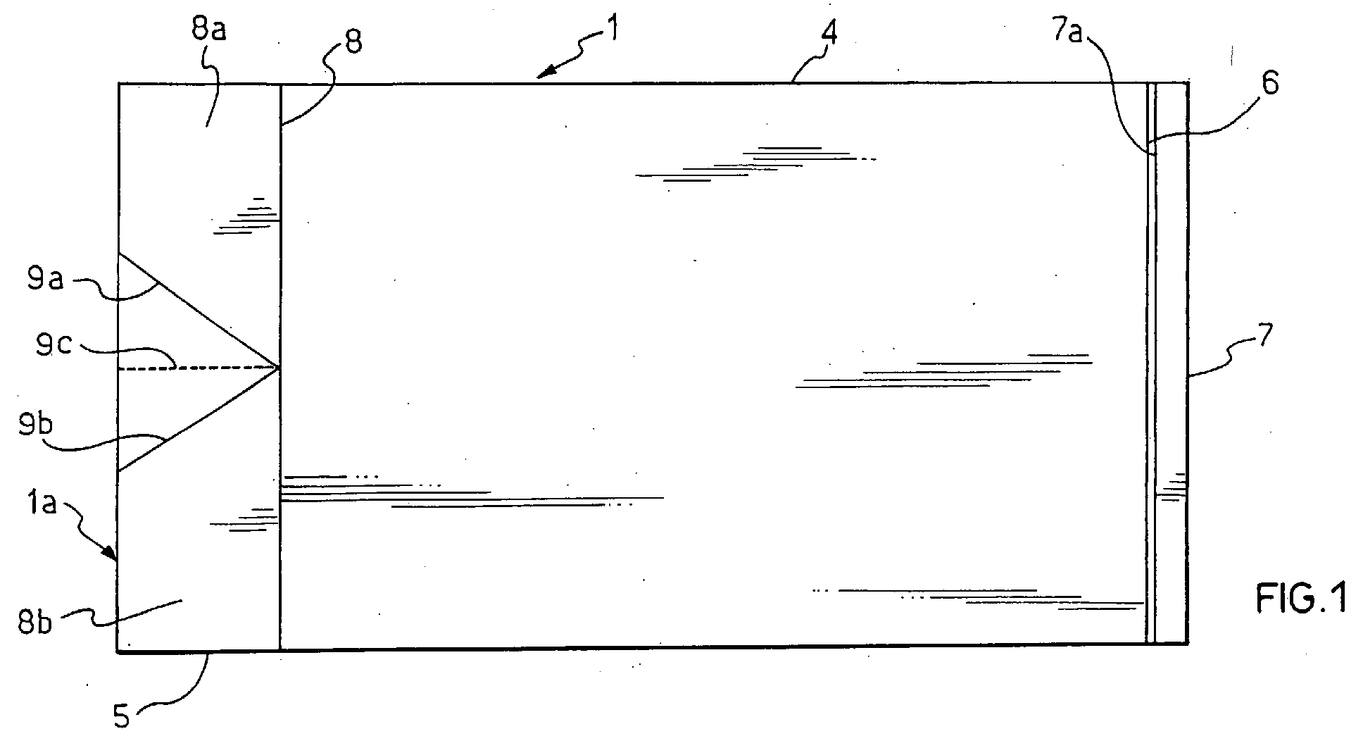
- the improved packaging bag shown in Fig. 1 is a transverse- or side-sealed bag 1 having a closed end 1a at which are joined together first and second superposed main panels 2 and 3 which are sealed along opposite edges 4 and 5 by a heat-sealing operation.
- the closed end 1a is a first fold in the film material providing the two plies defining the panels 2 and 3.
- the mouth of the bag is at the end opposite the closed end 1a and is formed by a singly folded portion 7 of the second main panel 3 and a cut edge 6 of the first main panel 2.
- the manufacture of the mouth end involves slitting the flattened tubular film of the plastic material used for the bag (12 in Figs. 3 and 4) in proximity of the second of the two folds thereof, the first fold being to define the closed end 1a, described above, of the bag.
- the production of the mouth end involves forming a cut at 7a in one of the two flat plies of the flattened tubular film in proximity to the second fold 7 referred to above, in order to separate the first main ply from the co-planar folded over part of the film margin at the fold 7.
- the folded end of the second main ply exhibits a double thickness of the film in one wall which projects beyond the end 6 of the first main ply (other wall), thereby (i) allowing easier pneumatic inflation of the bag mouth in order to open the bag 1 for loading purposes, and (ii) resisting wrinkling in that the increase in thickness of the end of the panel 3 at the folded end of the second ply helps to resist the tendency, which the bag material would otherwise have, to curl, as described above.
- the bag mouth is created by cutting only one of the plies of the flattened tubing along a line which is parallel to and in proximity of the second of the two longitudinal folds of the flattened tubing, no material is removed and the transverse seals to give the discrete bags are made directly on the longitudinally (machine direction) tensioned slit tubing. Therefore, there will be essentially a zero space between the edge 6 of the first ply and the margin 7a of the folded over portion of the second ply, i.e. said two edges will be adjacent one to the other.
- seal lines 8, 9a and 9b Close to the end 1a of the bag are optional seal lines 8, 9a and 9b the purpose of which will be described later.
- the film used for manufacturing the bag 1 may be a mono-layer film, but is preferably a multi-layer film having different functions for the individual layers of the bag.
- one of the intermediate layers of the bag material may be a barrier layer in order to control the transmission of gas (for example O 2 ) between the interior and exterior of the bag when sealed
- another of the layers of the bag material on the inside of bag will be a sealing layer facilitating sealing to a similar material for the purposes of closing the bag when loaded
- a third layer will be an abuse-resistant layer giving strength to the bag material.
- Other functions may also be provided, for example there may be tie layers between any of the above mentioned layers.
- the thickness of films suitable for the manufacture of transverse-sealed bags is typically comprised between about 35 and about 120 ⁇ m, preferably between about 40 and about 100 ⁇ m. Thicker films as well as thinner films, e.g. films 15, 20, 25, 30 ⁇ m thick may however be employed in the process of the present invention.
- Figs. 1 and 2 The apparatus for producing a bag of the type shown in Figs. 1 and 2 will now be described with reference to Figures 3 and 4, Fig. 3 showing a prior art apparatus for manufacturing a continuous strip of transverse- or side-sealed contiguous packaging bags, and Fig. 4 showing a modification which produces the bags in accordance with the present invention.
- FIG. 3 there is shown bag making apparatus 10 which processes a flattened tubular film 12 which may either have come straight from a bubble extrusion manufacturing plant or may have been previously formed by bubble extrusion and then rolled up for reuse at a later date at which point the roll is unwound so that the film can be fed to the bag making apparatus 10.
- the tubular material 12 arrives at a bag opening station 14 which includes a horizontally arranged knife blade 16 which can serve to slit the film 12 at the right-hand marginal fold as shown in Fig. 3.
- the film 12 arrives at an optional air introduction station 18 including an air nozzle 20 which is supported on the machine frame and is cantilevered to extend across the width of the flat folded film to introduce air near the left-hand fold line (which corresponds to the closed end 1a in Figs. 1 and 2). This may be helpful in case bags with the optional EZO feature, which will be described later, are manufactured.
- the film 12 arrives at a bottom forming station 22 which is optional but which in the present embodiment creates the seal lines 8, 9a and 9b to provide a particular easy open (EZO) configuration to the closed or bottom end of the bag so that the bag is substantially in accordance with US-A-6,260,705.
- EZO easy open
- the already slit film material then arrives at a transverse sealing station 24 including vertically closable and openable seal bars 26 and 28 which operate in synchronisation with stepwise advance of the tubular film material 12 so as to define a plurality of spaced transverse seal lines 30 which each include two spaced lines parallel sealing contiguous bags, one of such lines being associated with each of the contiguous bags, and between them a perforation line to allow the bags to be separated from one another at a downstream station.
- the bag material just at the slitting station 14 and downstream therefrom undergoes considerable curling particularly at the mouth end of the bag, and this results in pleats and wrinkles at the transverse sealing operation at station 24, particularly when the film material is of a heat shrinkable nature.
- the selvage 34 of the film material along the right-hand fold of the tubular material 12 is removed in its entirety by means of a vertically aligned trimming knife blade 32 which separates the selvage 34 to be sucked into an aspiration nozzle 36.
- the chain of perforated and transverse-sealed bags downstream of the knife 32 can then either be wound up for subsequent use, or be separated and reassociated in shingled or imbricated form on guide tapes, or possibly stacked vertically and delivered as a wicket of stacked bags, depending upon the type of bag loader for which they are to be used.
- the mouth of the bag along the right-hand edge, corresponding to the right-hand end 7 of the bag in Figs. 1 and 2 is closed by any convenient mechanism, preferably by heat seal bars, and then the bag can be subjected to a heat-shrinking operation which serves to tidy the structure of the bag around a product article which was loaded therein before the bag closing operation.
- the shrinking operation also results in formation of loose tabs or ears, illustrated by the portions 8a and 8b (Fig. 1) of the bag bottom to either side of the central V-notch shown therein (defined by the seal lines 9a and 9b), at which tearing of the bag can be initiated by pulling the two ears 8a and 8b apart from one another.
- This particular easy open feature is very useful for a shrink package but, as indicated above, is optional and can be used with or without the curl-preventing mouth structure in accordance with the present invention.
- Fig. 4 The difference between the prior art apparatus of Fig. 3 and the embodiment of the present invention shown in Fig. 4, which provides a bag in accordance with the present invention, resides in the fact that the film opening station 14 of Fig. 3 is replaced by a modified bag slitting station in Fig. 4, where the knife blade 17 is vertically aligned as compared with the horizontal alignment of the knife blade 16 at the film slitting station 14 of Fig. 3.
- the tube-slitting blade 17 is associated with a support 19 which carries both the knife blade 17 on the outside of the tubular film material 12 and an anvil (46 in Fig. 5) inside the tubular material so that the blade 17 can form a slit (illustrated at 7a in Fig.
- this slit 7a formed by the knife blade 17 in Fig. 4 forms, at a single stroke, the bag mouth in accordance with the present invention.
- the support 19 carrying the tube-slitting blade 17 and the anvil 46 is mounted on the machine frame so as to be released when desired, and so as to be adjustable in position in a direction transverse to the machine direction (i.e. to the direction of movement of the film web 12).
- the apparatus of Fig. 4 again includes the optional bottom-forming station 22 which may be used in conjunction with the optional air-introduction station 18 also shown in Figure 3.
- the optional air introduction station 18 can be located on the carrier 19 of the slitting station 15.
- the air introduction station 18 it is equally possible for the air introduction station 18 to be positioned downstream of the slitting station 15 but upstream of the optional bottom forming station 22.
- the transverse sealing station 24 in Fig. 4 is identical to that of Fig. 3 and will not be described in more detail.
- a further difference between the device of Fig. 4 in accordance with the present invention and the prior art embodiment of Fig. 3 is that there is no longer any need to remove the selvage material as shown at 32, 34, 36 in Fig. 3 because the reinforcement of the mouth portion, relying on the staggered mouth edges 6 and 7 (Fig. 2) and the folded over configuration of the projecting edge 7 (Fig. 1), rigidifies the bag structure sufficiently to eliminate the curling, and the absence of curling can be readily appreciated from the drawing of Fig. 4.
- the perforated chain of bags delivered at the far end of the apparatus as viewed in Fig. 4 can then either be immediately separated into individual bags for wicketing or imbricating or can remain as a chain of transverse-sealed bags for rolling up and storage.
- Both the Fig. 3 prior art embodiment and the Fig. 4 embodiment of the present invention include also a mouth separating blade 40 which serves merely to hold the right-hand edges of the upper 2 and lower 3 plies of the folded film 12 apart from one another and to guide them into the area between the jaws 26 and 28 of the transverse sealing station 24.
- the sealing station 24 in Fig. 4 operates in an intermittent manner synchronously with the stepwise movement of the bag chain.
- the modified apparatus 11 of Fig. 4 is threaded up in a similar manner except that the combined tube slitting station 15 and the optional air introduction station 18 provide for (i) the support 19 with the blade 17 to be removed from the bag path and for the nozzle then to be introduced between the opposed plies 2 and 3 of the centre folded film 12 once a slit (7a in Fig. 2) has been formed manually, and (ii) the air introduction station 18 (where fitted) to be similarly removed and then replaced after slitting the tube manually.
- the film material can then be advanced such that the anvil (46 in Fig.2) at the slitting station 15 and the air nozzle 20a of the optional air introduction station 18 can be introduced into the space between the two opposed plies (2 and 3 in Fig.
- the anvil 46 and the slitting blade 17 of Fig. 4 are also adjustable in a direction perpendicular to the machine direction for accommodating flattened tubular films 12 of different widths.
- the length of the transverse-sealed bags (that corresponds to the width of the flattened tubing 12) is typically comprised between about 15 and about 65 cm, preferably between about 16 and about 60 cm, and more preferably between about 18 and about 50 cm.
- the distance between the cut edge 6 of the first main panel 2 and the fold 7 of the second main panel 3, that corresponds to the length of the turned over lip, is typically below about 5 %, and preferaby below about 3 % of the total length of the bag.
- the length of the turned over lip is anyway less than 1 cm, more preferably less than 0.8 cm and even more preferably less than 0.5 cm.
- the bag represented in Fig. 1 is 18 cm long and has a turned over lip of 0.4 cm, corresponding to less than 3 % over the total length of the bag.
- the slitting blade will thus be positioned at a distance from the second fold 7 of the flattened tubing 12 that corresponds to the desired length of the turned over lip, i.e. preferably less than 1 cm, more preferably less than 0.8 cm and even more preferably less than 0.5 cm.
- Fig. 5 shows the knife blade 17 on the carrier 19 and in the process of forming the cut 7a in the upper ply 2 of the material 12a and leaving the underneath ply 3 uncut.
- the sub-carrier 42 is bolted to the main carrier 19 by means of bolts (not shown) which engage in holes 44 of the main carrier 19.
- the entire carrier 19 is releasably mounted on the machine frame so that it can be introduced into the already slit tubular film so that subsequent operation of the apparatus will continue the slitting action.
- the carrier 19, and the sub-carrier 42 and the air introduction nozzle 20a carried thereby, are in this way able to be rigidly mounted on the machine frame once it has been introduced into the already pre-positioned tubular film.
- the lower film ply 3 is shown in section along its entire length in Fig. 5 and the upper film ply 2 is only shown in section up to the point where it arrives at the tip of the slitting blade 17. Thereafter it has been slit and the exposed face 6 of the ply 2 can be seen, except where it is concealed behind the rear surface of the main carrier 19.
- Fig. 1 shows this optional characteristic as comprising a first seal line 8 which is parallel to and disposed inwardly of the fold defining the bottom end 1a of the bag, and a pair of additional seal lines 9a, 9b which start from the bottom end 1a of the bag and converge towards one another in a direction towards the seal line 8.
- these additional lines 9a and 9b meet at the seal line 8, but this is not essential to the operation of the easy open means defined by the lines 8, 9a, 9b.
- An "easy-open” (EZO) pre-cut line 9c extends longitudinally of the bag (i.e. perpendicularly to the seal line 8 and to the bottom end 1a of the bag so as to define a point of initiation of a tear when the bag is to be open. This opening operation will occur after the open end of the bag at 6, 7 has been sealed and the thus sealed bag has been subjected to a shrinking operation.
- the bag closing operation involves placing the loaded bag into a vacuum chamber which exposes the exterior of the sealed bag to reduced pressure causing the bag to balloon slightly, and causing the sealed pockets 8a, 8b of the bottom end of the bag to inflate slightly to present the tabs or ears mentioned above.
- the thus partially evacuated and sealed bag is subjected to a heat shrinking operation, either in a hot air shrink tunnel or in a shrink bath, whereupon the bag material between the seal line 8 and the closed mouth end of the bag will hug the contours of the product within the bag to provide a tidy package, but the pockets 8a, 8b will protrude from the surface, in the manner described in US-A-6,260,705.
- perforation line 9c is optional, and that instead some other form of tear-initiating formation could be provided.
- a hole is formed centrally in the triangular region defined between the fold line 1a of the tubular film material and the converging additional seal lines 9a, 9b.
- tear-initiating means could be omitted and one could rely simply on the fact that it is easy to apply tearing tension to the film material simply by grasping the two ears defined by the pockets 8a, 8b and pulling them apart.
- the tear-initiating bottom formation 8, 8a, 8b, 9a, 9b, 9c is optional and it would have been possible for the bag to be finished with simply the fold line 1a defining the closed end of the product compartment of the bag.
Landscapes
- Engineering & Computer Science (AREA)
- Mechanical Engineering (AREA)
- Making Paper Articles (AREA)
Abstract
Description
- The present invention relates to a packaging bag, particularly a transverse- or side-sealed bag of plastics film.
- In the manufacture of transverse- or side-sealed plastic packaging bags a problem arises from time to time in that the mouth edge of the bag may tend to curl during the manufacturing process. This problem is particularly noticeable when producing the bags from a shrink film, due to the application of heat to achieve the transverse or side seal between contiguous bags in a stream being produced, particularly when working with film thicknesses of smaller values. One solution to this problem has been to add a final step of trimming off the mouth edge material after formation of the transverse-sealed bags, in order that freshly exposed mouth edge will have a straight, uncurled configuration in the finished bag.
- It is an object of the present invention to provide a novel packaging bag which is resistant to the curling experienced with the prior art bags.
- A further object of the present invention is to provide a method of producing packaging bags which are resistant to the curling problem of the prior art.
- Yet a further object of the present invention is to provide an apparatus for producing packaging bags which are resistant to this curling problem.
- According to a first aspect of the present invention there is provided a packaging bag comprising opposed first and second film plies joined at a closed end of the bag and sealed along lateral edges of the bag, said plies defining an open mouth end having a first edge of the first ply and a second edge of the second ply which projects beyond the first edge of the first ply and comprises a folded over film portion to exhibit double thickness at the exposed end of the second ply, wherein the margin of the folded over portion of the second ply is disposed adjacent to the first edge of the first ply so as to provide a substantially constant thickness of the bag across the mouth and the projecting portion.
- The turned over lip defines the mouth edge of a longer side of the bag which thus slightly projects beyond the edge of the shorter opposite side of the bag. The turned over lip also therefore presents a rigidifying effect, which is particularly helpful in the case of packaging bags with a thickness at the smaller end of the available range of materials to be used, i.e. a light weight of film.
- The packaging bags according to this first aspect may be presented as discrete, separate, bags, possibly reassociated in shingled or imbricated form on guide tapes, or stacked vertically and delivered as a wicket of stacked bags. They may also be presented in the form of a continuous strip of contiguous bags that can be easily separated one from the other, e.g. due to the presence of weakening lines such as pre-perforated lines, positioned between the transverse seals of each bag and the transverse seals of the immediately preceding and following bags.
- A further aspect of the present invention provides an apparatus for manufacturing a bag according to the first aspect, comprising means for feeding a flattened tubular film material, having first and second marginal folds, along a film path, means for transversely sealing said flattened tubular film at regularly spaced locations to define the joins between contiguous transverse-sealed bags formed from said tubular film material, means for taking up said succession of transverse sealed bags from said transverse sealing station, and means for slitting one flat wall of said flattened tubular film material in proximity of said first fold of said film material to define said second mouth edge extending beyond said first mouth edge, said slitting means being mounted upstream of said transverse sealing station.
- A third aspect of the present invention provides a method of manufacturing a bag according to the first aspect, comprising feeding a flattened tubular film material along a machine direction while exhibiting first and second superposed plies extending between first and second marginal folds of said tubular film material, slitting said first ply in proximity of said first marginal fold of said flattened tubular film material while leaving said second ply unslit whereby said second ply has a turned over edge at said first marginal fold of the tubular film material, downstream of said slitting station transversely sealing said tubular film material along a plurality of regularly spaced transverse seal lines which extend into said second ply at said turned over edge in proximity to the first marginal fold of the tubular film material, and delivering the plurality of transverse-sealed packaging bags thus formed.
- By leaving the turned over lip in place at the mouth edge of the finished bag, it is possible to utilize all of the film material of the flattened tubular film used as starting material for the manufacture of side-sealed bags, and this both provides better economy of material and also eliminates the complication of the need to remove the trimmed mouth edge as has been conventional as a way of avoiding curling in the finished bags.
- A fourth aspect of the invention provides a method of packaging, comprising taking a bag according to the first aspect, or a bag made by the method of the third aspect, and pneumatically inflating the mouth of said bag to separate the edge of said shorter first ply from said projecting edge of the second ply to initiate opening of the bag, and subsequently holding the bag open and introducing a product article into a respective said open bag.
- In order that the present invention may more readily be understood the following description is given, merely by way of example, with reference to the accompanying drawings in which:
- Fig. 1 is a top plan view of an embodiment of packaging bag in accordance with the first aspect of the present invention, in this case incorporating an optional easy open (EZO) feature;
- Fig. 2 is a side sectional view of the bag of Fig. 1, taken along the line II-II of Fig. 1;
- Fig. 3 is a perspective view of a prior art form of bag making apparatus and process;
- Fig. 4 is a view corresponding to Fig. 3 but showing an embodiment of the bag making process and apparatus in accordance with the present invention in the special case of the EZO bag embodiment of Fig. 1; and
- Fig. 5 is a sectional view, taken on the line V-V of Fig. 2, showing the knife and anvil of the slitting station of the apparatus of Fig. 4.
-
- The improved packaging bag shown in Fig. 1 is a transverse- or side-sealed bag 1 having a closed
end 1a at which are joined together first and second superposed main panels 2 and 3 which are sealed alongopposite edges 4 and 5 by a heat-sealing operation. In this embodiment the closedend 1a is a first fold in the film material providing the two plies defining the panels 2 and 3. - The mouth of the bag is at the end opposite the closed
end 1a and is formed by a singly foldedportion 7 of the second main panel 3 and acut edge 6 of the first main panel 2. The manufacture of the mouth end involves slitting the flattened tubular film of the plastic material used for the bag (12 in Figs. 3 and 4) in proximity of the second of the two folds thereof, the first fold being to define the closedend 1a, described above, of the bag. - The production of the mouth end involves forming a cut at 7a in one of the two flat plies of the flattened tubular film in proximity to the
second fold 7 referred to above, in order to separate the first main ply from the co-planar folded over part of the film margin at thefold 7. As a result, at the mouth end the folded end of the second main ply exhibits a double thickness of the film in one wall which projects beyond theend 6 of the first main ply (other wall), thereby (i) allowing easier pneumatic inflation of the bag mouth in order to open the bag 1 for loading purposes, and (ii) resisting wrinkling in that the increase in thickness of the end of the panel 3 at the folded end of the second ply helps to resist the tendency, which the bag material would otherwise have, to curl, as described above. - In the bag according to the present invention the bag mouth is created by cutting only one of the plies of the flattened tubing along a line which is parallel to and in proximity of the second of the two longitudinal folds of the flattened tubing, no material is removed and the transverse seals to give the discrete bags are made directly on the longitudinally (machine direction) tensioned slit tubing. Therefore, there will be essentially a zero space between the
edge 6 of the first ply and themargin 7a of the folded over portion of the second ply, i.e. said two edges will be adjacent one to the other. - Close to the
end 1a of the bag areoptional seal lines - The film used for manufacturing the bag 1 may be a mono-layer film, but is preferably a multi-layer film having different functions for the individual layers of the bag. For example, (i) one of the intermediate layers of the bag material may be a barrier layer in order to control the transmission of gas (for example O2) between the interior and exterior of the bag when sealed, (ii) another of the layers of the bag material on the inside of bag will be a sealing layer facilitating sealing to a similar material for the purposes of closing the bag when loaded, and (iii) a third layer will be an abuse-resistant layer giving strength to the bag material. Other functions may also be provided, for example there may be tie layers between any of the above mentioned layers. The thickness of films suitable for the manufacture of transverse-sealed bags, including those according to the present invention, is typically comprised between about 35 and about 120 µm, preferably between about 40 and about 100 µm. Thicker films as well as thinner films,
e.g. films - The apparatus for producing a bag of the type shown in Figs. 1 and 2 will now be described with reference to Figures 3 and 4, Fig. 3 showing a prior art apparatus for manufacturing a continuous strip of transverse- or side-sealed contiguous packaging bags, and Fig. 4 showing a modification which produces the bags in accordance with the present invention.
- In Fig. 3 there is shown
bag making apparatus 10 which processes a flattenedtubular film 12 which may either have come straight from a bubble extrusion manufacturing plant or may have been previously formed by bubble extrusion and then rolled up for reuse at a later date at which point the roll is unwound so that the film can be fed to thebag making apparatus 10. Initially thetubular material 12 arrives at abag opening station 14 which includes a horizontally arrangedknife blade 16 which can serve to slit thefilm 12 at the right-hand marginal fold as shown in Fig. 3. Next thefilm 12 arrives at an optionalair introduction station 18 including anair nozzle 20 which is supported on the machine frame and is cantilevered to extend across the width of the flat folded film to introduce air near the left-hand fold line (which corresponds to the closedend 1a in Figs. 1 and 2). This may be helpful in case bags with the optional EZO feature, which will be described later, are manufactured. - Next the
film 12 arrives at abottom forming station 22 which is optional but which in the present embodiment creates theseal lines - The already slit film material then arrives at a
transverse sealing station 24 including vertically closable andopenable seal bars tubular film material 12 so as to define a plurality of spacedtransverse seal lines 30 which each include two spaced lines parallel sealing contiguous bags, one of such lines being associated with each of the contiguous bags, and between them a perforation line to allow the bags to be separated from one another at a downstream station. - As can be seen in Fig. 3, the bag material just at the
slitting station 14 and downstream therefrom, undergoes considerable curling particularly at the mouth end of the bag, and this results in pleats and wrinkles at the transverse sealing operation atstation 24, particularly when the film material is of a heat shrinkable nature. In order to remove the unsightly curled mouth region from the bag, and to guard against the possibility of that curling leading to difficulties in opening the bag by a pneumatic opening device at the loading station, the selvage 34 of the film material along the right-hand fold of thetubular material 12 is removed in its entirety by means of a vertically alignedtrimming knife blade 32 which separates the selvage 34 to be sucked into anaspiration nozzle 36. - The chain of perforated and transverse-sealed bags downstream of the
knife 32 can then either be wound up for subsequent use, or be separated and reassociated in shingled or imbricated form on guide tapes, or possibly stacked vertically and delivered as a wicket of stacked bags, depending upon the type of bag loader for which they are to be used. - During the bag closing operation the mouth of the bag along the right-hand edge, corresponding to the right-
hand end 7 of the bag in Figs. 1 and 2, is closed by any convenient mechanism, preferably by heat seal bars, and then the bag can be subjected to a heat-shrinking operation which serves to tidy the structure of the bag around a product article which was loaded therein before the bag closing operation. Where the optionalbottom forming device 22 is present, the shrinking operation also results in formation of loose tabs or ears, illustrated by theportions seal lines ears - In order to complete description of the prior art apparatus of Fig.3, it is sufficient to indicate that initially the flattened
tubular film 12 is withdrawn from the supply and pulled past theslitting station 14, the optionalair introduction station 18, the optionalbottom forming station 22, the mouth separatingblade 40 and theheat sealing station 24 while itsjaws film material 12 can be inserted therebetween. Then the right-hand edge of the tubular film material at thefilm slitting station 14 is slit and the tubular material is placed over thehorizontal knife blade 16 such that the blade enters the slit which has thus been formed, and then subsequent movement of the tubular film material in the machine direction illustrated by arrow 21 will cause theblade 16 to continue slitting the film passing thereover. - Finally the leading end of the continuous perforated strip of bags is drawn to the
slitting blade 32 where another slit is formed by theblade 32 to isolate the selvage 34 for continuous removal of the selvage 34 as themachine 10 continues to operate with stepwise advancing of the film material synchronised with intermittent operation of thetransverse sealing station 24. - The difference between the prior art apparatus of Fig. 3 and the embodiment of the present invention shown in Fig. 4, which provides a bag in accordance with the present invention, resides in the fact that the
film opening station 14 of Fig. 3 is replaced by a modified bag slitting station in Fig. 4, where theknife blade 17 is vertically aligned as compared with the horizontal alignment of theknife blade 16 at thefilm slitting station 14 of Fig. 3. In Fig. 4 the tube-slitting blade 17 is associated with asupport 19 which carries both theknife blade 17 on the outside of thetubular film material 12 and an anvil (46 in Fig. 5) inside the tubular material so that theblade 17 can form a slit (illustrated at 7a in Fig. 2) in the upper ply 2 of thefilm 12 without penetrating the lower ply 3 of the film. It will be readily understood that thisslit 7a formed by theknife blade 17 in Fig. 4 forms, at a single stroke, the bag mouth in accordance with the present invention. Thesupport 19 carrying the tube-slitting blade 17 and theanvil 46 is mounted on the machine frame so as to be released when desired, and so as to be adjustable in position in a direction transverse to the machine direction (i.e. to the direction of movement of the film web 12). - The apparatus of Fig. 4 again includes the optional bottom-forming
station 22 which may be used in conjunction with the optional air-introduction station 18 also shown in Figure 3. Preferably the optionalair introduction station 18 can be located on thecarrier 19 of theslitting station 15. However, it is equally possible for theair introduction station 18 to be positioned downstream of theslitting station 15 but upstream of the optionalbottom forming station 22. - The
transverse sealing station 24 in Fig. 4 is identical to that of Fig. 3 and will not be described in more detail. - A further difference between the device of Fig. 4 in accordance with the present invention and the prior art embodiment of Fig. 3 is that there is no longer any need to remove the selvage material as shown at 32, 34, 36 in Fig. 3 because the reinforcement of the mouth portion, relying on the staggered mouth edges 6 and 7 (Fig. 2) and the folded over configuration of the projecting edge 7 (Fig. 1), rigidifies the bag structure sufficiently to eliminate the curling, and the absence of curling can be readily appreciated from the drawing of Fig. 4.
- As in the case of the Fig. 3 embodiment, the perforated chain of bags delivered at the far end of the apparatus as viewed in Fig. 4 can then either be immediately separated into individual bags for wicketing or imbricating or can remain as a chain of transverse-sealed bags for rolling up and storage.
- Both the Fig. 3 prior art embodiment and the Fig. 4 embodiment of the present invention include also a
mouth separating blade 40 which serves merely to hold the right-hand edges of the upper 2 and lower 3 plies of the foldedfilm 12 apart from one another and to guide them into the area between thejaws station 24. As in the Fig. 3 apparatus, the sealingstation 24 in Fig. 4 operates in an intermittent manner synchronously with the stepwise movement of the bag chain. - The modified
apparatus 11 of Fig. 4 is threaded up in a similar manner except that the combinedtube slitting station 15 and the optionalair introduction station 18 provide for (i) thesupport 19 with theblade 17 to be removed from the bag path and for the nozzle then to be introduced between the opposed plies 2 and 3 of the centre foldedfilm 12 once a slit (7a in Fig. 2) has been formed manually, and (ii) the air introduction station 18 (where fitted) to be similarly removed and then replaced after slitting the tube manually. The film material can then be advanced such that the anvil (46 in Fig.2) at the slittingstation 15 and theair nozzle 20a of the optionalair introduction station 18 can be introduced into the space between the two opposed plies (2 and 3 in Fig. 1) while theknife blade 17 is positioned above the upper ply 2 and is able to slit only the upper ply while leaving the lower ply intact as illustrated in Fig. 2. The rest of the threading-up operation is the same for theapparatus 11 of Fig. 4 as it is for theapparatus 10 of Fig. 3, except that there is no need to form the downstream slit atknife blade 32 for the selvage-removing operation. - The
anvil 46 and theslitting blade 17 of Fig. 4 are also adjustable in a direction perpendicular to the machine direction for accommodating flattenedtubular films 12 of different widths. - The length of the transverse-sealed bags (that corresponds to the width of the flattened tubing 12) is typically comprised between about 15 and about 65 cm, preferably between about 16 and about 60 cm, and more preferably between about 18 and about 50 cm.
- The distance between the
cut edge 6 of the first main panel 2 and thefold 7 of the second main panel 3, that corresponds to the length of the turned over lip, is typically below about 5 %, and preferaby below about 3 % of the total length of the bag. Preferably the length of the turned over lip is anyway less than 1 cm, more preferably less than 0.8 cm and even more preferably less than 0.5 cm. As an example, the bag represented in Fig. 1 is 18 cm long and has a turned over lip of 0.4 cm, corresponding to less than 3 % over the total length of the bag. - The slitting blade will thus be positioned at a distance from the
second fold 7 of the flattenedtubing 12 that corresponds to the desired length of the turned over lip, i.e. preferably less than 1 cm, more preferably less than 0.8 cm and even more preferably less than 0.5 cm. - In order to illustrate more clearly the operation of the combined
air introduction station 18 and thefilm slitting station 15 in Fig. 4, reference will now be made to Fig. 5 which shows theknife blade 17 on thecarrier 19 and in the process of forming thecut 7a in the upper ply 2 of thematerial 12a and leaving the underneath ply 3 uncut. - In order to establish the precise configuration for Fig. 5 it should be noted that this drawing is taken on the line V-V of Fig. 2, in other words at the location of the
slit 7a of Fig. 2, and for that reason asub-carrier 42 which has a clamp (not shown) to support theblade 17 thereon is illustrated in broken lines in Fig. 5 but in fact this is just in front of the plane of the paper and would therefore, strictly speaking, not be visible in Fig. 5. In other words, theblade 17 is clamped to the back face of thesub-carrier 42, and that face is in the plane of the paper of Fig. 2. - The
sub-carrier 42 is bolted to themain carrier 19 by means of bolts (not shown) which engage inholes 44 of themain carrier 19. - As mentioned earlier, the
entire carrier 19 is releasably mounted on the machine frame so that it can be introduced into the already slit tubular film so that subsequent operation of the apparatus will continue the slitting action. - The
carrier 19, and thesub-carrier 42 and theair introduction nozzle 20a carried thereby, are in this way able to be rigidly mounted on the machine frame once it has been introduced into the already pre-positioned tubular film. - It should be noted that the lower film ply 3 is shown in section along its entire length in Fig. 5 and the upper film ply 2 is only shown in section up to the point where it arrives at the tip of the
slitting blade 17. Thereafter it has been slit and the exposedface 6 of the ply 2 can be seen, except where it is concealed behind the rear surface of themain carrier 19. - In order to explain in more detail the way in which the tear initiation formation provided by the bottom-defining
means 22 is structured, reference will now again be made to Fig. 1 which shows this optional characteristic as comprising afirst seal line 8 which is parallel to and disposed inwardly of the fold defining thebottom end 1a of the bag, and a pair ofadditional seal lines bottom end 1a of the bag and converge towards one another in a direction towards theseal line 8. In this particular embodiment theseadditional lines seal line 8, but this is not essential to the operation of the easy open means defined by thelines - An "easy-open" (EZO) pre-cut line 9c extends longitudinally of the bag (i.e. perpendicularly to the
seal line 8 and to thebottom end 1a of the bag so as to define a point of initiation of a tear when the bag is to be open. This opening operation will occur after the open end of the bag at 6, 7 has been sealed and the thus sealed bag has been subjected to a shrinking operation. - It is possible for the bag closing operation to involve placing the loaded bag into a vacuum chamber which exposes the exterior of the sealed bag to reduced pressure causing the bag to balloon slightly, and causing the sealed
pockets seal line 8 and the closed mouth end of the bag will hug the contours of the product within the bag to provide a tidy package, but thepockets - The fact that there is air within these
pockets air introduction nozzle 20a applying air at the fold line which defines theclosed end 1a of the bag helps to ensure that thesepockets pockets seal lines - It will of course be understood that the existence of the perforation line 9c is optional, and that instead some other form of tear-initiating formation could be provided. One possibility would be for a hole to be formed centrally in the triangular region defined between the
fold line 1a of the tubular film material and the convergingadditional seal lines fold line 1a, again within the triangular zone defined between thefold line 1a and the convergingadditional seal lines pockets - As indicated above, the tear-initiating
bottom formation fold line 1a defining the closed end of the product compartment of the bag.
Claims (18)
- A packaging bag comprising opposed first (2) and second (3) film plies joined at a closed end (1a) of the bag and sealed along lateral edges (4, 5) of the bag, said plies (2, 3) defining an open mouth end having a first edge (6) of the first ply (2) and a second edge (7) of the second ply (3) which projects beyond the first edge (6) of the first ply and comprises a folded over film portion to exhibit double thickness at the exposed end of the second ply (3), wherein the margin (7a) of the folded over portion of the second ply (3) is disposed adjacent to the edge (6) of the first ply (2) so as to provide a substantially constant thickness of the bag across the mouth and projecting portion (7).
- A packaging bag according to claim 1, wherein the length of the folded over film portion is less than about 5 %, preferably less than about 3 % of the total length of the bag.
- A packaging bag according to claim 1, wherein the length of the folded over film portion is less than 1 cm, preferably less than 0.8 cm and more preferably less than 0.5 cm.
- A packaging bag according to any of the preceding claims wherein the two plies (2, 3) are joined at a fold line defining the closed end (1a).
- A packaging bag according to any of the preceding claims, including at the closed end of the bag a first seal line (8) joining the first and second plies (2, 3) and further seal lines (9a, 9b) extending from the closed bottom (1a) of the bag and converging toward one another in a direction towards the further seal line (8).
- A packaging bag according to claim 5, wherein said further seal lines (9a, 9b) meet at the said additional seal line (8).
- A continuous strip of transverse-sealed packaging bags that can be easily separated one from the other, wherein the transverse-sealed bags are in accordance to any of the preceding claims.
- Apparatus for manufacturing a plurality of packaging bags according to claim 1, comprising means for feeding a flattened tubular film material (12) having first and second marginal folds along a film path, means (24) for transversely sealing said tubular film at regularly spaced locations to define the joins between contiguous transverse-sealed bags to be formed from said tubular film material, means for taking up said succession of transverse sealed bags from said transverse sealing station, and means (17) for slitting one flat wall (2) of said flattened tubular film material (12) in proximity to said first fold of said film material to define said second mouth edge (7) extending beyond said first mouth edge (6), said slitting means (17) being mounted upstream of said transverse sealing station (24).
- Apparatus according to claim 8, and further including means defining a tear-initiating formation (8, 9a, 9b) at said closed end (1a) of the bags by heat sealing said flattened tubular film close to its second marginal fold.
- Apparatus according to claim 9 and including an air introduction nozzle (20a) extending transversely across and within said tubular film material either at said slitting station (15) or downstream of it but before the heat sealing of the flattened tubular film close to its second marginal fold, for introducing air into the space between said superposed plies (2, 3).
- Apparatus according to any one of claims 8 to 10, wherein said slitting station comprises an anvil (46) arranged to be disposed within said tubular film material at said slitting station and to extend upstream from a carrier (19), and a slitting blade (17) disposed adjacent said anvil (46) whereby said slitting blade will slit only said first ply (2) passing over said anvil (46).
- Apparatus according to claim 11, wherein said anvil (46) and said slitting blade (17) are fixed to said carrier (19), and including means for releasably attaching said main carrier (19) to the machine frame.
- A method of making a plurality of packaging bags according to claim 1, comprisinga. feeding a flattened tubular film material (12) along a machine direction while exhibiting first and second superposed plies (2, 3) extending between first and second marginal folds of said tubular film material,b. slitting said first ply (2) in proximity to said first marginal fold of said flattened tubular film material while leaving said second ply unslit whereby said second ply has a turned over edge at said first marginal fold of the tubular film material (12),c. downstream of said slitting station (15) transversely sealing said tubular film material along a plurality of regularly spaced transverse seal lines which extend into said second ply at said turned over edge in proximity to the first marginal fold of the tubular film material (12), andd. delivering the plurality of transverse-sealed packaging bags thus formed.
- A method according to claim 13, wherein said transverse sealing operation applies closely spaced seal lines defining lateral margins (4, 5) of contiguous transverse-sealed bags, and between said closely spaced seal lines a line of weakness permitting subsequent separation of said contiguous bags from one another.
- A method according to claim 13 or claim 14, and including the further step of separating said transverse-sealed bags from one another and presenting them in a package ready for subsequent use at a bag loader.
- A method according to any one of claims 13 to 15, and including the further step of applying, at said second marginal fold of the tubular film material, a longitudinally extending seal line spaced inwardly from said second fold of the tubular film material, and applying additional seal lines which extend from said second fold line in a converging manner towards said additional seal line.
- A method according to any one of claims 13 to 16, wherein said tubular film material is formed of a heat-shrinkable plastic film.
- A method of packaging comprising taking a bag according to any one of claims 1 to 6 or manufactured by the method of any one of claims 13 to 17, and pneumatically inflating the mouth of said bag to separate the edge (6) of said shorter first ply (2) from said projecting edge (7) of the second ply (3) to initiate opening of the bag, and subsequently holding the bag open and introducing a product article into a respective said open bag.
Priority Applications (1)
| Application Number | Priority Date | Filing Date | Title |
|---|---|---|---|
| EP03011985A EP1375366A1 (en) | 2002-06-25 | 2003-05-28 | Packaging bag, and method of and apparatus for manufacturing the same |
Applications Claiming Priority (3)
| Application Number | Priority Date | Filing Date | Title |
|---|---|---|---|
| EP02254428 | 2002-06-25 | ||
| EP02254428A EP1375365A1 (en) | 2002-06-25 | 2002-06-25 | Packaging bag, and method of and apparatus for manufacturing the same |
| EP03011985A EP1375366A1 (en) | 2002-06-25 | 2003-05-28 | Packaging bag, and method of and apparatus for manufacturing the same |
Publications (1)
| Publication Number | Publication Date |
|---|---|
| EP1375366A1 true EP1375366A1 (en) | 2004-01-02 |
Family
ID=29718300
Family Applications (1)
| Application Number | Title | Priority Date | Filing Date |
|---|---|---|---|
| EP03011985A Withdrawn EP1375366A1 (en) | 2002-06-25 | 2003-05-28 | Packaging bag, and method of and apparatus for manufacturing the same |
Country Status (1)
| Country | Link |
|---|---|
| EP (1) | EP1375366A1 (en) |
Cited By (2)
| Publication number | Priority date | Publication date | Assignee | Title |
|---|---|---|---|---|
| CN112026264A (en) * | 2020-08-13 | 2020-12-04 | 浙江新合发联宾包装科技有限责任公司 | A cutting device for packaging bags |
| CN115489774A (en) * | 2022-09-16 | 2022-12-20 | 安徽博日生物科技有限公司 | Automatic filling and film sealing equipment and method for rotating disc type extraction tube |
Citations (12)
| Publication number | Priority date | Publication date | Assignee | Title |
|---|---|---|---|---|
| US2873566A (en) * | 1957-07-01 | 1959-02-17 | Amsco Packaging Machinery Inc | Merchandise container and method of making a merchandise package therefrom |
| US3358906A (en) * | 1966-12-29 | 1967-12-19 | Lamson Paragon Ltd | Heat sealable plastic material bags for coins |
| DE1486527A1 (en) * | 1965-12-20 | 1969-04-24 | Mittelrheinische Plastik Gmbh | Carrying bag made of thermoplastic plastic |
| DE1940404A1 (en) * | 1969-08-08 | 1971-04-22 | Herkules Papiersackfabriken Br | Behaeltnis in the form of a sack, bag or the like. from plastic film and process for its manufacture |
| US3647060A (en) * | 1969-03-25 | 1972-03-07 | Mobil Oil Corp | Roll double-pocketed bag structures |
| GB2128575A (en) * | 1982-10-04 | 1984-05-02 | Grace W R & Co | Taped multibags |
| US4616472A (en) * | 1985-10-10 | 1986-10-14 | W. R. Grace & Co., Cryovac Div. | Method and apparatus for loading side-seal bags |
| JPH03251163A (en) * | 1990-02-28 | 1991-11-08 | Eikou Kikaku:Kk | Method for reducing bag for putting cigar end |
| JPH0928436A (en) * | 1995-05-15 | 1997-02-04 | Ikeda Takahiro | Umbrella bag |
| DE19618814A1 (en) * | 1996-05-10 | 1997-11-13 | Auto Cover Gmbh Produktion Und | Car seat cover production |
| US6260705B1 (en) * | 1999-11-15 | 2001-07-17 | Cryovac, Inc. | Heat shrinkable pouch |
| US6363694B1 (en) * | 1998-04-06 | 2002-04-02 | International Paper Company | Bag for use in an automatic bag filling process |
-
2003
- 2003-05-28 EP EP03011985A patent/EP1375366A1/en not_active Withdrawn
Patent Citations (12)
| Publication number | Priority date | Publication date | Assignee | Title |
|---|---|---|---|---|
| US2873566A (en) * | 1957-07-01 | 1959-02-17 | Amsco Packaging Machinery Inc | Merchandise container and method of making a merchandise package therefrom |
| DE1486527A1 (en) * | 1965-12-20 | 1969-04-24 | Mittelrheinische Plastik Gmbh | Carrying bag made of thermoplastic plastic |
| US3358906A (en) * | 1966-12-29 | 1967-12-19 | Lamson Paragon Ltd | Heat sealable plastic material bags for coins |
| US3647060A (en) * | 1969-03-25 | 1972-03-07 | Mobil Oil Corp | Roll double-pocketed bag structures |
| DE1940404A1 (en) * | 1969-08-08 | 1971-04-22 | Herkules Papiersackfabriken Br | Behaeltnis in the form of a sack, bag or the like. from plastic film and process for its manufacture |
| GB2128575A (en) * | 1982-10-04 | 1984-05-02 | Grace W R & Co | Taped multibags |
| US4616472A (en) * | 1985-10-10 | 1986-10-14 | W. R. Grace & Co., Cryovac Div. | Method and apparatus for loading side-seal bags |
| JPH03251163A (en) * | 1990-02-28 | 1991-11-08 | Eikou Kikaku:Kk | Method for reducing bag for putting cigar end |
| JPH0928436A (en) * | 1995-05-15 | 1997-02-04 | Ikeda Takahiro | Umbrella bag |
| DE19618814A1 (en) * | 1996-05-10 | 1997-11-13 | Auto Cover Gmbh Produktion Und | Car seat cover production |
| US6363694B1 (en) * | 1998-04-06 | 2002-04-02 | International Paper Company | Bag for use in an automatic bag filling process |
| US6260705B1 (en) * | 1999-11-15 | 2001-07-17 | Cryovac, Inc. | Heat shrinkable pouch |
Non-Patent Citations (2)
| Title |
|---|
| PATENT ABSTRACTS OF JAPAN vol. 016, no. 049 (C - 0908) 7 February 1992 (1992-02-07) * |
| PATENT ABSTRACTS OF JAPAN vol. 1997, no. 06 30 June 1997 (1997-06-30) * |
Cited By (3)
| Publication number | Priority date | Publication date | Assignee | Title |
|---|---|---|---|---|
| CN112026264A (en) * | 2020-08-13 | 2020-12-04 | 浙江新合发联宾包装科技有限责任公司 | A cutting device for packaging bags |
| CN115489774A (en) * | 2022-09-16 | 2022-12-20 | 安徽博日生物科技有限公司 | Automatic filling and film sealing equipment and method for rotating disc type extraction tube |
| CN115489774B (en) * | 2022-09-16 | 2024-06-04 | 安徽博日生物科技有限公司 | Automatic filling and film sealing equipment and method for rotary disc type extraction pipe |
Similar Documents
| Publication | Publication Date | Title |
|---|---|---|
| EP2261130B1 (en) | Consumer bags and processes of manufacture and dispensing systems for consumer bags | |
| EP0730524B1 (en) | Bags and method of making bags | |
| US6793613B2 (en) | Bag blocks | |
| EP1072526A2 (en) | Reinforced reclosable package seals | |
| EP0219996B1 (en) | Method and apparatus for loading side-seal bags | |
| JPH11510461A (en) | Zippered films and bags | |
| CA1333587C (en) | Plastic film bag with integral plastic film tie element and associated fabrication methods | |
| US3332324A (en) | Method and apparatus for the manufacture of a combined web of material suitable for the manufacture of pouches | |
| US20040001652A1 (en) | Packaging bag, and method of and apparatus for manufacturing the same | |
| US6015373A (en) | Method for wicket-top converting of a cross-laminated synthetic resin fiber mesh bag | |
| US6080093A (en) | Apparatus for wicket-top converting of a cross-laminated synthetic resin fiber mesh bag | |
| US3579397A (en) | Process of manufacturing bags having tear strips and consisting of synthetic thermoplastics | |
| EP3572221B1 (en) | Production method for pleated film, and production method of pleated packaging body | |
| US4822437A (en) | Method and apparatus for making non-roping thermoplastic draw tape for thermoplastic bags | |
| US20240239556A1 (en) | Method and machine for manufacturing a flexible envelope-like bag, particularly with reinforcement | |
| EP0108798A1 (en) | Method and apparatus for continuous formation of reclosable article wrappers | |
| EP0453105A2 (en) | Packaging with tear string and resealable closure | |
| WO2002028724A2 (en) | Multi-layered bag and method of manufacture | |
| JP2013154927A (en) | Device for forming unsealing section of bag in bag making filling machine | |
| EP2764990B1 (en) | Method of producing a container | |
| WO2017108567A1 (en) | Method and apparatus for making draw strip bags | |
| JPH08216302A (en) | Outer bag for carrying and bag making machine for manufacturing the outer bag | |
| JPS5884752A (en) | Method and device for manufacturing packing bag with valve | |
| JPS6127253B2 (en) | ||
| GB2164919A (en) | Plastic bags suitable for automatic packaging |
Legal Events
| Date | Code | Title | Description |
|---|---|---|---|
| PUAI | Public reference made under article 153(3) epc to a published international application that has entered the european phase |
Free format text: ORIGINAL CODE: 0009012 |
|
| AK | Designated contracting states |
Kind code of ref document: A1 Designated state(s): AT BE BG CH CY CZ DE DK EE ES FI FR GB GR HU IE IT LI LU MC NL PT RO SE SI SK TR |
|
| AX | Request for extension of the european patent |
Extension state: AL LT LV MK |
|
| 17P | Request for examination filed |
Effective date: 20040519 |
|
| AKX | Designation fees paid |
Designated state(s): AT BE BG CH CY CZ DE DK EE ES FI FR GB GR HU IE IT LI LU MC NL PT RO SE SI SK TR |
|
| 17Q | First examination report despatched |
Effective date: 20081203 |
|
| STAA | Information on the status of an ep patent application or granted ep patent |
Free format text: STATUS: THE APPLICATION IS DEEMED TO BE WITHDRAWN |
|
| 18D | Application deemed to be withdrawn |
Effective date: 20081202 |