EP1375347B1 - Temperature compensating inflation device and method - Google Patents
Temperature compensating inflation device and method Download PDFInfo
- Publication number
- EP1375347B1 EP1375347B1 EP03013785A EP03013785A EP1375347B1 EP 1375347 B1 EP1375347 B1 EP 1375347B1 EP 03013785 A EP03013785 A EP 03013785A EP 03013785 A EP03013785 A EP 03013785A EP 1375347 B1 EP1375347 B1 EP 1375347B1
- Authority
- EP
- European Patent Office
- Prior art keywords
- stage
- gas
- pressure
- pressure vessel
- stage gas
- Prior art date
- Legal status (The legal status is an assumption and is not a legal conclusion. Google has not performed a legal analysis and makes no representation as to the accuracy of the status listed.)
- Expired - Lifetime
Links
- 238000000034 method Methods 0.000 title claims description 12
- 230000000977 initiatory effect Effects 0.000 claims description 22
- 239000000463 material Substances 0.000 claims description 9
- 239000003999 initiator Substances 0.000 claims description 5
- 238000004891 communication Methods 0.000 claims description 4
- 239000012530 fluid Substances 0.000 claims description 4
- 230000000704 physical effect Effects 0.000 claims 5
- 239000012080 ambient air Substances 0.000 claims 1
- 230000003111 delayed effect Effects 0.000 claims 1
- 239000007789 gas Substances 0.000 description 100
- 238000010304 firing Methods 0.000 description 23
- CURLTUGMZLYLDI-UHFFFAOYSA-N Carbon dioxide Chemical compound O=C=O CURLTUGMZLYLDI-UHFFFAOYSA-N 0.000 description 14
- 239000000203 mixture Substances 0.000 description 14
- XKRFYHLGVUSROY-UHFFFAOYSA-N Argon Chemical compound [Ar] XKRFYHLGVUSROY-UHFFFAOYSA-N 0.000 description 10
- 239000001569 carbon dioxide Substances 0.000 description 7
- 229910002092 carbon dioxide Inorganic materials 0.000 description 7
- 239000004020 conductor Substances 0.000 description 6
- 229910052786 argon Inorganic materials 0.000 description 5
- 239000002360 explosive Substances 0.000 description 4
- PAWQVTBBRAZDMG-UHFFFAOYSA-N 2-(3-bromo-2-fluorophenyl)acetic acid Chemical compound OC(=O)CC1=CC=CC(Br)=C1F PAWQVTBBRAZDMG-UHFFFAOYSA-N 0.000 description 2
- IJGRMHOSHXDMSA-UHFFFAOYSA-N Atomic nitrogen Chemical compound N#N IJGRMHOSHXDMSA-UHFFFAOYSA-N 0.000 description 2
- NDYLCHGXSQOGMS-UHFFFAOYSA-N CL-20 Chemical compound [O-][N+](=O)N1C2N([N+]([O-])=O)C3N([N+](=O)[O-])C2N([N+]([O-])=O)C2N([N+]([O-])=O)C3N([N+]([O-])=O)C21 NDYLCHGXSQOGMS-UHFFFAOYSA-N 0.000 description 2
- GQPLMRYTRLFLPF-UHFFFAOYSA-N Nitrous Oxide Chemical compound [O-][N+]#N GQPLMRYTRLFLPF-UHFFFAOYSA-N 0.000 description 2
- TZRXHJWUDPFEEY-UHFFFAOYSA-N Pentaerythritol Tetranitrate Chemical compound [O-][N+](=O)OCC(CO[N+]([O-])=O)(CO[N+]([O-])=O)CO[N+]([O-])=O TZRXHJWUDPFEEY-UHFFFAOYSA-N 0.000 description 2
- 239000000026 Pentaerythritol tetranitrate Substances 0.000 description 2
- PXIPVTKHYLBLMZ-UHFFFAOYSA-N Sodium azide Chemical compound [Na+].[N-]=[N+]=[N-] PXIPVTKHYLBLMZ-UHFFFAOYSA-N 0.000 description 2
- 238000010276 construction Methods 0.000 description 2
- AXZAYXJCENRGIM-UHFFFAOYSA-J dipotassium;tetrabromoplatinum(2-) Chemical compound [K+].[K+].[Br-].[Br-].[Br-].[Br-].[Pt+2] AXZAYXJCENRGIM-UHFFFAOYSA-J 0.000 description 2
- 239000007788 liquid Substances 0.000 description 2
- UZGLIIJVICEWHF-UHFFFAOYSA-N octogen Chemical compound [O-][N+](=O)N1CN([N+]([O-])=O)CN([N+]([O-])=O)CN([N+]([O-])=O)C1 UZGLIIJVICEWHF-UHFFFAOYSA-N 0.000 description 2
- 238000012354 overpressurization Methods 0.000 description 2
- 229960004321 pentaerithrityl tetranitrate Drugs 0.000 description 2
- FGIUAXJPYTZDNR-UHFFFAOYSA-N potassium nitrate Chemical compound [K+].[O-][N+]([O-])=O FGIUAXJPYTZDNR-UHFFFAOYSA-N 0.000 description 2
- 229910001487 potassium perchlorate Inorganic materials 0.000 description 2
- VWDWKYIASSYTQR-UHFFFAOYSA-N sodium nitrate Chemical compound [Na+].[O-][N+]([O-])=O VWDWKYIASSYTQR-UHFFFAOYSA-N 0.000 description 2
- 239000013589 supplement Substances 0.000 description 2
- XTFIVUDBNACUBN-UHFFFAOYSA-N 1,3,5-trinitro-1,3,5-triazinane Chemical compound [O-][N+](=O)N1CN([N+]([O-])=O)CN([N+]([O-])=O)C1 XTFIVUDBNACUBN-UHFFFAOYSA-N 0.000 description 1
- 241000233805 Phoenix Species 0.000 description 1
- RTAQQCXQSZGOHL-UHFFFAOYSA-N Titanium Chemical compound [Ti] RTAQQCXQSZGOHL-UHFFFAOYSA-N 0.000 description 1
- QCWXUUIWCKQGHC-UHFFFAOYSA-N Zirconium Chemical compound [Zr] QCWXUUIWCKQGHC-UHFFFAOYSA-N 0.000 description 1
- KAMAYGDPQDHVSH-UHFFFAOYSA-N [Cr](=O)(=O)([O-])[O-].[Ca+2].[B+3] Chemical compound [Cr](=O)(=O)([O-])[O-].[Ca+2].[B+3] KAMAYGDPQDHVSH-UHFFFAOYSA-N 0.000 description 1
- 230000003416 augmentation Effects 0.000 description 1
- 238000002485 combustion reaction Methods 0.000 description 1
- 239000000470 constituent Substances 0.000 description 1
- 238000007796 conventional method Methods 0.000 description 1
- 238000001816 cooling Methods 0.000 description 1
- 230000006378 damage Effects 0.000 description 1
- 230000009977 dual effect Effects 0.000 description 1
- 230000000694 effects Effects 0.000 description 1
- 238000004880 explosion Methods 0.000 description 1
- 239000004744 fabric Substances 0.000 description 1
- 239000000446 fuel Substances 0.000 description 1
- 238000010348 incorporation Methods 0.000 description 1
- WETZJIOEDGMBMA-UHFFFAOYSA-L lead styphnate Chemical compound [Pb+2].[O-]C1=C([N+]([O-])=O)C=C([N+]([O-])=O)C([O-])=C1[N+]([O-])=O WETZJIOEDGMBMA-UHFFFAOYSA-L 0.000 description 1
- GUWHRJQTTVADPB-UHFFFAOYSA-N lithium azide Chemical compound [Li+].[N-]=[N+]=[N-] GUWHRJQTTVADPB-UHFFFAOYSA-N 0.000 description 1
- 238000002844 melting Methods 0.000 description 1
- 230000008018 melting Effects 0.000 description 1
- 238000012986 modification Methods 0.000 description 1
- 230000004048 modification Effects 0.000 description 1
- 238000012544 monitoring process Methods 0.000 description 1
- 229910052757 nitrogen Inorganic materials 0.000 description 1
- 239000001272 nitrous oxide Substances 0.000 description 1
- 239000007800 oxidant agent Substances 0.000 description 1
- 239000004323 potassium nitrate Substances 0.000 description 1
- 235000010333 potassium nitrate Nutrition 0.000 description 1
- 239000000047 product Substances 0.000 description 1
- 239000003380 propellant Substances 0.000 description 1
- 238000007665 sagging Methods 0.000 description 1
- 239000004317 sodium nitrate Substances 0.000 description 1
- 235000010344 sodium nitrate Nutrition 0.000 description 1
- 229910052719 titanium Inorganic materials 0.000 description 1
- 239000010936 titanium Substances 0.000 description 1
- 230000008016 vaporization Effects 0.000 description 1
- XLYOFNOQVPJJNP-UHFFFAOYSA-N water Substances O XLYOFNOQVPJJNP-UHFFFAOYSA-N 0.000 description 1
- 229910052726 zirconium Inorganic materials 0.000 description 1
Images


Classifications
-
- B—PERFORMING OPERATIONS; TRANSPORTING
- B64—AIRCRAFT; AVIATION; COSMONAUTICS
- B64D—EQUIPMENT FOR FITTING IN OR TO AIRCRAFT; FLIGHT SUITS; PARACHUTES; ARRANGEMENT OR MOUNTING OF POWER PLANTS OR PROPULSION TRANSMISSIONS IN AIRCRAFT
- B64D25/00—Emergency apparatus or devices, not otherwise provided for
- B64D25/08—Ejecting or escaping means
- B64D25/14—Inflatable escape chutes
Definitions
- This invention relates to an inflation device for inflating an inflatable aircraft evacuation slide or other inflatable device.
- a conventional method of quickly evacuating a large number of passengers from an aircraft is to provide multiple emergency exits, each of which is equipped with an inflatable evacuation slide.
- Current state of the art emergency evacuation slide systems comprise an inflatable evacuation slide which is stored in an uninflated folded state together with a source of inflation gas.
- the source of inflation gas typically comprises a gas generator, stored compressed gas, or a combination thereof.
- Pyrotechnic gas generators have an advantage in that they are small, lightweight, and produce a high volume of gas, however, the high temperature gas produced by a gas generator alone can cause numerous problems including sagging of the evacuation slide as the inflation gas cools and, in some cases, melting of the fabric out of which the inflation slide if fabricated.
- Use of stored compressed gas by itself although simple, implicates a weight penalty that must be paid for carrying a pressure vessel having sufficient capacity (in terms of volume and pressure) to inflate the evacuation slide over the wide operational temperature range specified for such slides.
- a large drop in temperature occurs as the gases expand, often causing ice to form, which can block the flow of gas.
- state-of-the-art emergency evacuation slide evacuation systems typically comprise a hybrid inflator, which utilizes a stored compressed gas together with a pyrotechnic gas generator.
- the pyrotechnic gas generator augments the stored compressed gas by providing additional gas, as well as heat to counteract the effects of the expansion-induced cooling of the compressed gas as it expands out of the pressure vessel.
- the first parts of Claims 1 and 9 refer to an apparatus and method as disclosed in US-A-5,613,702.
- This reference describes an apparatus for inflating an inflatable vehicle occupant restraint such as an airbag.
- the apparatus comprises a vessel containing a pressurized gas source and a second stage gas source comprising an ignitable material.
- a controller actuates a first initiator for opening the gas passage from the vessel to the airbag at an initial time in response to the occurence of a vehicle collision.
- the controller actuates a second initiator for actuating the ignitable material after the lapse of a delay time.
- the delay time is determined by the controller with reference to the ambient temperature.
- the storage vessel must withstand the overpressure at 74°C (165°F) caused by the pyrotechnic gas generator, even though use of the pyrotechnic gas generator at 74°C (165°F) causes the inflation system to produce substantially more gas than is necessary to inflate the evacuation slide.
- the apparatus of the present invention is defined by Claim 1 and the method of the present invention is defined by Claim 9.
- the delay of the ignition of the second stage gas source terminates when the pressure in the vessel has dropped below a threshold level.
- the present invention comprises a dual stage hybrid inflation device including a first stage gas source comprising a pressurized gas stored in a first stage pressure vessel and a second stage gas source having a gas output directed into the first stage pressure vessel.
- the first stage pressure vessel is in fluid communication with an inflatable device such as an aircraft emergency evacuation slide via a combination valve/regulator and one or more conventional aspirators.
- a pressure transducer (or normally open pressure switch) senses the pressure in the first stage pressure vessel.
- the inflation system is initiated by a voltage signal, for example from a sensor mounted to detect opening of the aircraft door.
- the voltage signal opens the valve of the first stage pressure vessel and simultaneously sends a voltage signal to arm the firing circuit for the pyrotechnic gas generator comprising the second stage gas source.
- the pressure switch which is normally open above a threshold pressure, interrupts a voltage signal to or from the firing circuit, which causes the firing circuit to delay initiation of the pyrotechnic gas generator if the pressure in the first stage pressure vessel is above the threshold leveL This prevents the pyrotechnic gas generator from being initiated when the additional heat and gas would overpressurize the first stage pressure vessel.
- the pressure in the first stage pressure vessel drops. If the pressure in the first stage pressure vessel drops below the threshold pressure of the pressure switch, the pressure switch closes, which permits the firing circuit to initiate the second stage gas source.
- the appropriate augmentation of the compressed first stage gas can be realized without the necessity of designing the first stage pressure vessel to withstand initiation of the pyrotechnic gas generator under maximum inflation pressure conditions. This enables the first stage pressure vessel to be of a lighter weight construction thereby saving substantially both in costs and fuel savings for the aircraft on which such systems are installed.
- the pressure switch is replaced with a pressure transducer.
- An external circuit monitors the pressure signal and closes a circuit or otherwise provides a signal to the second stage gas source when the pressure has dropped below the threshold level.
- the pressure transducer is replaced by a temperature transducer.
- An external timing circuit closes a circuit or otherwise sends a signal to initiate the second stage gas source based on known pressure versus time behavior of the inflation system.
- the present invention is directed to a method and apparatus for inflating an inflatable device such as an aircraft emergency evacuation slide over a wide range of operating temperatures.
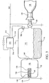
- An inflator incorporating features the present invention is shown in FIG. 1.
- Inflator 100 comprises a first stage gas source 110 and a second stage gas source 112.
- First stage gas source 110 comprises a pressure vessel 114 containing a mixture of compressed inflation gases 116.
- inflation gas mixture 116 comprises approximately a 2:1 ratio of carbon dioxide to argon. In general, however, the mixture of inflation gases, as well as the ratio of gases, can vary based on the particular application.
- compressed gas means and refers to gas that is in a gaseous state under pressure as well as gas that has changed phase to a liquid state under pressure.
- Pressure vessel 114 has a gas exit opening 118 to which is attached a regulator valve 120.
- Regulator valve 120 is normally closed but is remotely electrically actuated via an input terminal 122 which is adapted to receive a voltage signal that opens regulator valve 120 in a conventional manner.
- Regulator valve 120 is in fluid communication with an output duct 124 leading to the inflatable device 128 through one or more conventional aspirators 126.
- any of the pressurized inflation gases well known in the art may be used for inflation gas mixture 116.
- gases that may be utilized in accordance with the present invention either alone or in combination include, but are not limited to carbon dioxide, nitrogen, chlorofluorocarbons, bromofluorocarbons, nitrous oxide and argon.
- the combination of carbon dioxide and argon is preferred, however, because of the ability of carbon dioxide to liquify, and thus require a minimum of storage volume, and the high specific heat of argon which enables it to absorb substantial heat from a pyrotechnic gas generator.
- Second stage gas source 112 comprises a pyrotechnic gas generator 130 either alone or in combination with a compressed gas 132 (such as disclosed in U.S. Patent No. 5,988,438 to Lewis, et al. and assigned to the Assignee of the present invention).
- Pyrotechnic gas generator 130 comprises a pyrotechnic material 134 which may either be in stick form or pressed into a container (not shown). Pyrotechnic material 134 is initiated by an initiator or squib 136 comprising a bridge wire 138 and an initiation composition 140.
- Pyrotechnic material 134 may be any pyrotechnic gas generator material such as sodium-azide, or lithium-azide coupled with an oxidizer such as sodium nitrate, potassium nitrate, potassium perchlorate and the like but preferably comprises ammonium nitrate in combination with a secondary explosive such as cyclotrimethylene trinitramine (RDX); cyclotetramethylene tetranitramine (HMX); pentaerythritol tetranitrate (PETN), hexanitrohexaazaisowurtzitane (CL20) or similar energizers that produce a high volume of gaseous combustion products with little or no particulates.
- RDX cyclotrimethylene trinitramine
- HMX cyclotetramethylene tetranitramine
- PETN pentaerythritol tetranitrate
- CL20 hexanitrohexaazaisowurtzitane
- a most preferred gas generator material is UPCO 8043, a slow burning, relatively insensitive ammonium nitrate base propellant available from Universal Propulsion Company, Inc. of Phoenix, Arizona.
- the initiation composition 140 may be any heat sensitive primary explosive such as a mixture of zirconium or titanium with potassium perchlorate, boron calcium chromate, lead styphnate or similar primary explosive suitable for use in hot wire electro explosive devices.
- Firing circuit 70 may be may be a safe and arming firing circuit such as disclosed in U.S. Patent No. 5,335,598, the teaching of which is incorporated herein by reference to the extent necessary to supplement this specification.
- the valve portion of regulator valve 120 may be a conventional solenoid operated valve, explosively initiated valve or other conventional valve that may be remotely actuated. Additionally, although regulator valve 120 in the illustrative embodiment of FIG.1 is electrically actuated, regulator valve 120 may also be mechanically actuated (e.g. by a lanyard or other mechanical means) in which case other means for simultaneously applying a voltage to input terminal 152 of pressure switch 150 and input terminal 72 of firing circuit 70 (e.g. a switch applying a battery voltage) would be provided. Similarly, although the regulator portion of regulator valve 120 in the illustrative embodiment is a conventional sliding spool regulator, other regulation means, such as a simple orifice may be used in accordance with the present invention.
- the pressure within pressure vessel 114 may be from approximately 70 bar (1,000 psi) at -74°C (-65° F) to 281 bar (4,000 psi) at 74°C (165° F).
- the aspirator 126 performs most efficiently with an inlet pressure of 28,1 bar (400 psi). Therefore, in addition to providing the opening function upon initiation, regulator valve 120 also operates to regulate the pressure within pressure vessel 114 down to 28,1 bar (400 psi) at the inlet to aspirator 126.
- Pressure switch 150 is normally open above a threshold pressure (e.g. 141 bar (2,000 psi)). Accordingly, as long as the pressure within pressure vessel 114 is above the threshold pressure of pressure switch 150, the voltage signal at input terminal 152 of pressure switch 150 does not appear at output terminal 154 of pressure switch 150 and thus does not appear at trigger terminal 74 of firing circuit 70. As a result, firing circuit 70 does not initiate pyrotechnic gas generator 130. When the pressure in pressure vessel 114 drops below the threshold pressure of pressure switch 150, however, pressure switch 150 closes and the voltage signal at input terminal 152 is transmitted to the trigger terminal 74 of firing circuit 70, which in turn causes firing circuit 70 to initiate squib 136 of pyrotechnic gas generator 130.
- a threshold pressure e.g. 141 bar (2,000 psi)
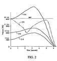
- FIG. 2 illustrates projected pressure-time profiles of the illustrative embodiment of FIG.1 operating at three different operating temperatures.
- the pressure-time profile at -74°C (-65°F) is represented by the line having reference numeral 210.
- the initial pressure in first stage pressure vessel 114 is 70 bar (1,000 psi), which is below the 141 bar (2,000 psi) threshold pressure of pressure switch 150. Accordingly, pressure switch 150 is closed. Therefore, when a voltage signal is received along input conductor 142, squib 136 initiates pyrotechnic gas generator 130 simultaneous with the opening of regulator valve 120.
- first stage pressure vessel 114 is 141 bar (2,000 psi). Accordingly, pressure switch 150 is just at the point of closing. Therefore, when a voltage signal is received along input conductor 142, squib 136 initiates pyrotechnic gas generator 130 simultaneous with the opening of regulator valve 120.
- first stage pressure vessel 114 is already 281 bar (4,000 psi). If the pyrotechnic gas generator 130 were initiated simultaneous with the opening of valve 120, as indicated by the line having reference numeral 214, the pressure inside first stage pressure vessel 114 would rise rapidly to in excess of 352 bar (5,000 psi), substantially above the 351 bar (4,100 psi) maximum operating pressure (MOP) of first stage pressure vessel 114. With the incorporation of pressure switch 150, however, as indicated by the line having reference numeral 216, upon receipt of a voltage signal along input conductor 142, regulator valve 120 opens and the pressure within first stage pressure vessel 114 begins to drop as gas expands out of first stage pressure vessel 114.
- first stage pressure vessel 114 Only when the pressure in first stage pressure vessel 114 drops below the threshold pressure of pressure switch 150 is the voltage signal communicated to bridge wire 138 of squib 136 thereby initiating pyrotechnic gas generator 130. Upon the initiation pyrotechnic gas generator 130, the pressure in first stage pressure vessel 114 rises again, however, it does not exceed the 351 bar (4,100 psi) MOP of first stage pressure vessel 114.
- a hybrid gas generator/compressed gas inflator having sufficient capacity to inflate an inflatable device at the coldest temperature may not require the gas generator to function at all at the highest temperature range.
- a simple timing circuit or other device may be incorporated to preclude the initiation of the pyrotechnic gas generator if the pressure does not drop below the threshold pressure within a predetermined period of time (e.g. within the first four seconds after opening the regulator valve).
- the inflatable device will simply be inflated completely using the compressed gas without having to vent the excess inflation gas that would be produced by the gas generator.
- FIG. 3 An alternative embodiment of an inflator incorporating features of the present invention is shown in FIG. 3.
- pressure switch 150 is replaced with a pressure transducer 350.
- Initiation of pyrotechnic gas generator 130 is controlled by an external initiation circuit 310, which may be a safe and arming firing circuit such as disclosed in U.S. Patent No. 5,335,598, the teaching of which is incorporated herein by reference to the extent necessary to supplement this specification.
- a voltage signal is received along input conductor 342 from an external source such as a sensor mounted to an aircraft emergency evacuation door.
- the voltage signal causes regulator valve 120 to open immediately allowing the inflation gas mixture 116 to begin to flow into inflatable device 128 via aspirator 126.
- Circuit 310 monitors the pressure signal from pressure transducer 350 via input 314 and produces a firing signal to initiator 136 via output 316 when the pressure signal from pressure transducer 350 indicates that the pressure in first stage pressure vessel 114 has dropped below the predetermined threshold.
- circuit 310 can include additional circuitry for monitoring the status of pressure transducer 350 and provide an error signal in the event pressure transducer 350 shows an out-of-range reading or otherwise appears to be malfunctioning.
- FIG. 4 depicts another alternative embodiment of an inflator incorporating features of the present invention.
- the pressure transducer 350 has been replaced with a temperature transducer 450 and circuit 310 has been replaced with timing and firing circuit 410.
- a voltage signal is transmitted along input conductor 442 in response to the opening of an aircraft emergency evacuation door.
- the voltage signal causes regulator valve 120 to open immediately to allow inflation gas mixture 116 to begin inflating inflatable device 128 via aspirator 126. Simultaneously, the voltage signal is received at input 412 of timing/firing circuit 410.
- timing/firing circuit 410 can be preprogrammed to initiate squib 136 after a predetermined delay based on the temperature signal received from temperature transducer 450 at input 414 of timing/firing circuit 410.
- the advantage of using a timing/firing circuit 410 is that a temperature transducer such as a thermocouple may be less costly to incorporate into first stage pressure vessel 114 and may be more reliable since a thermocouple involves no moving parts.
Landscapes
- Business, Economics & Management (AREA)
- Emergency Management (AREA)
- Engineering & Computer Science (AREA)
- Aviation & Aerospace Engineering (AREA)
- Air Bags (AREA)
Description
Claims (14)
- Apparatus for inflating an inflatable device comprising:characterized in thata first stage gas source (110) comprising;
a first stage pressure vessel (114) having a gas exit opening (118),
a pressurized cold gas (116) stored within said first stage pressure vessel, and
a remotely actuated valve (120), in fluid communication with said gas exit opening (118) and responsive to an external signal for opening to provide a gas flow path between said first stage pressure vessel (114) and said inflatable device (128);a second stage gas source (112) having a gas output (148) directed into said first stage pressure vessel (114);an initiator (136) for initiating said second stage gas source,a sensor (150) sensing the pressure of the pressurized cold gas in the first stage pressure vessel; andan electronic circuit (70, 310, 410) having an input for receiving a signal from said sensor and an output for initiating said second stage gas source (112), said electronic circuit operating to delayinitiation of said second stage gas source (112) for a period of time after said remotely actuated valve (120) opens, the length of said period of time being determined based upon said output signal from said sensor (150),
the delay of the ignition of the second stage gas source (112) is governed by said electronic circuit in response to an output signal provided by the sensor (150) if the pressure is above a threshold level, so that said delay terminates when the pressure in the vessel (114) has dropped below the threshold level. - The apparatus of Claim 1, wherein:said remotely actuated valve (120) is electrically actuated.
- The apparatus of Claim 1, wherein:said second stage gas source comprises a pyrotechnic gas generator (130).
- The apparatus of Claim 1, wherein:said sensor (150) having an output signal indicative of one of the physical properties of the pressurized cold gas comprises a pressure transducer.
- The apparatus of Claim 4, wherein:said electronic circuit (310, 410) comprises means for receiving a voltage signal indicative of the opening of said remotely actuated valve (120) and wherein said pressure transducer is interposed between said signal indicative of the opening of said remotely actuated valve (120) and said second stage gas source (112) such that said signal is interrupted until the pressure of said pressurized cold gas drops below a predetermined level.
- The apparatus of Claim 5, further comprising:means for generating a voltage signal indicative of the opening of an aircraft emergency evacuation exit door, said voltage signal operating to open said remotely actuated valve and to provide said voltage signal indicative of the opening of said remotely actuated valve (120).
- The apparatus of Claim 1, wherein:said sensor (450) having an output signal indicative of one of the physical properties of the pressurized cold gas comprises a temperature transducer.
- The apparatus of Claim 7, wherein:said electronic circuit comprises an electronic timing circuit having a first input (312) for receiving a signal indicative of the opening of said remotely actuated valve, a second input (314) for receiving a signal from said temperature transducer (350) and an output (316) for providing a delayed signal for initiating said second stage gas source (112).
- A method for inflating an inflatable device comprising:characterized in thatstoring a first stage gas in a first stage pressure vessel (114);sensing the pressure of said first stage gas in said first stage pressure vessel (114) with a transducer (150, 350, 450) and providing an output signal indicative thereof;opening a remotely operated valve (120) in response to an external signal to release said first stage gas through said valve into said inflatable device (128); andthereafter initiating a second stage gas source (112) having a gas output directed into said first stage pressure vessel (114), said initiating of said second stage gas source occurring after a delay period, the length of said delay period being determined by said output signal indicative of said one of the physical properties of said first stage gas,whereby said second stage gas source augments said first stage gas flowing through said valve into said inflatable device,
the delay of the ignition of the second stage gas source (112) is governed by said electronic circuit in response to an output signal provided by the sensor (150) if the pressure is above a threshold level, so that said delay terminates when the pressure in the vessel (114) has dropped below the threshold level. - The method of Claim 9, wherein:said one of the physical properties of said first stage gas comprises the pressure of said first stage gas (116), wherein the length of said delay period comprises the length of time necessary for said pressure of said first stage gas to drop below a predetermined level.
- The method of Claim 10, wherein:said one of the physical properties of said first stage gas comprises the temperature of said first stage gas.
- The method of Claim 9, wherein:wherein said means for initiating said second stage gas source comprises an electrically initiated squib (136) operable to initiate said pyrotechnic material (134).said second stage gas source (112) comprises:a second stage pressure vessel (144) having a gas exit aperture in fluid communication with said first stage pressure vessel (114);a frangible seal (148) disposed in said gas exit aperture, said frangible seal operable to open said gas exit aperture to permit gas to flow through said gas exit aperture when pressure in said second stage pressure vessel exceeds a predetermined level;a compressed gas stored within said second stage pressure vessel (144); anda pyrotechnic material (134) contained within said second stage pressure vessel (144),
- The method of Claim 9, wherein:said external signal comprises a signal indicative of the opening of an aircraft emergency exit door.
- The method of Claim 9, further comprising:flowing said first stage gas through an aspirator to entrain ambient air prior to said first stage gas flowing into said inflatable device.
Applications Claiming Priority (2)
| Application Number | Priority Date | Filing Date | Title |
|---|---|---|---|
| US10/184,716 US6860205B2 (en) | 2002-06-26 | 2002-06-26 | Temperature compensating inflation device |
| US184716 | 2002-06-26 |
Publications (2)
| Publication Number | Publication Date |
|---|---|
| EP1375347A1 EP1375347A1 (en) | 2004-01-02 |
| EP1375347B1 true EP1375347B1 (en) | 2005-12-14 |
Family
ID=29717975
Family Applications (1)
| Application Number | Title | Priority Date | Filing Date |
|---|---|---|---|
| EP03013785A Expired - Lifetime EP1375347B1 (en) | 2002-06-26 | 2003-06-18 | Temperature compensating inflation device and method |
Country Status (3)
| Country | Link |
|---|---|
| US (1) | US6860205B2 (en) |
| EP (1) | EP1375347B1 (en) |
| DE (1) | DE60302717T2 (en) |
Cited By (1)
| Publication number | Priority date | Publication date | Assignee | Title |
|---|---|---|---|---|
| WO2026060089A1 (en) * | 2024-09-11 | 2026-03-19 | Air Cruisers Company, LLC | Inflation system with vessel for inflatable safety device |
Families Citing this family (14)
| Publication number | Priority date | Publication date | Assignee | Title |
|---|---|---|---|---|
| US7032778B2 (en) * | 2003-01-30 | 2006-04-25 | Goodrich Corporation | Overpressure limiting hybrid inflator |
| JP2005350020A (en) * | 2004-06-14 | 2005-12-22 | Takata Corp | Inflator and air bag device |
| US7490795B2 (en) * | 2005-08-31 | 2009-02-17 | Goodrich Corporation | Aircraft evacuation slide with primary gas relief valve |
| US9814938B2 (en) * | 2013-02-28 | 2017-11-14 | Ras Technology Sàrl | Portable device for inflating a bag |
| US9150462B2 (en) * | 2013-08-02 | 2015-10-06 | Goodrich Corporation | Heated inflation system |
| CN103933958A (en) * | 2014-04-22 | 2014-07-23 | 苏州聚康新材料科技有限公司 | Preparation method of sol with photo-catalytic activity |
| US10612677B2 (en) * | 2017-02-13 | 2020-04-07 | Goodrich Corporation | Solenoid valve for inflation system |
| US10612723B2 (en) * | 2017-02-13 | 2020-04-07 | Goodrich Corporation | Solenoid valve for inflation system |
| CN110778399B (en) * | 2019-11-04 | 2020-09-29 | 湖北航天化学技术研究所 | Gas production supercharging device |
| US11554999B2 (en) * | 2019-11-15 | 2023-01-17 | Goodrich Corporation | Inflation systems for evacuation slides and life rafts |
| US11835179B2 (en) * | 2020-04-16 | 2023-12-05 | Goodrich Corporation | Systems and methods for monitoring evacuation assembly charge cylinders |
| US11639227B2 (en) * | 2020-07-13 | 2023-05-02 | Goodrich Corporation | Inflation assemblies for evacuation systems |
| US12466566B2 (en) | 2021-05-27 | 2025-11-11 | Goodrich Corporation | Time-based control system for inflatable evacuation slide |
| US12134478B2 (en) | 2021-11-30 | 2024-11-05 | Goodrich Corporation | Control systems and methods for inflatable evacuation slide |
Family Cites Families (23)
| Publication number | Priority date | Publication date | Assignee | Title |
|---|---|---|---|---|
| US3458009A (en) * | 1967-11-28 | 1969-07-29 | Global Systems | Evacuation slide |
| US3731843A (en) * | 1971-06-10 | 1973-05-08 | Susquehanna Corp | Gas source |
| US4213635A (en) * | 1978-11-13 | 1980-07-22 | Toyota Kodosha Kogyo Kabushiki Kaisha | Two-stage air bag system |
| US4368009A (en) * | 1980-08-15 | 1983-01-11 | The B. F. Goodrich Company | Aspirator |
| US5263740A (en) * | 1991-12-17 | 1993-11-23 | Trw Inc. | Hybrid air bag inflator |
| US5344186A (en) * | 1992-12-24 | 1994-09-06 | Trw Vehicle Safety Systems Inc. | Inflator assembly |
| EP0790158B1 (en) * | 1993-03-23 | 2000-06-14 | Trw Inc. | Inflator assembly |
| US5335598A (en) * | 1993-05-07 | 1994-08-09 | Universal Propulsion Company, Inc. | Timing and firing circuitry |
| US5350192A (en) * | 1993-08-11 | 1994-09-27 | Trw Vehicle Safety Systems Inc. | Inflator assembly |
| US5468015A (en) * | 1994-06-21 | 1995-11-21 | Trw Vehicle Safety Systems Inc. | Apparatus for inflating an inflatable vehicle occupant restraint |
| AU676653B2 (en) | 1995-05-10 | 1997-03-13 | Morton International, Inc. | Multiple level fluid fueled air bag inflator |
| US5613702A (en) * | 1996-02-23 | 1997-03-25 | Trw Vehicle Safety Systems Inc. | Apparatus for inflating an inflatable vehicle occupant restraint |
| US5820162A (en) * | 1996-03-21 | 1998-10-13 | Airbelt Systems, Llc. | Airbag system inflator |
| US5992881A (en) * | 1997-07-01 | 1999-11-30 | Trw Vehicle Safety Systems Inc. | Vehicle occupant protection apparatus with multiple stage inflator |
| US6168199B1 (en) * | 1997-09-04 | 2001-01-02 | Trw Vehicle Safety Systems Inc. | Inflator for an inflatable vehicle occupant protection device |
| US5906394A (en) * | 1997-11-18 | 1999-05-25 | Trw Inc. | Completely non-pyrotechnic air bag inflator |
| US6161481A (en) * | 1998-02-26 | 2000-12-19 | Trw Inc. | Air bag inflator |
| US5988438A (en) * | 1998-03-16 | 1999-11-23 | Universal Propulsion Company, Inc. | Apparatus for rapid inflation of inflatable object and related method |
| GB2342622A (en) | 1998-10-16 | 2000-04-19 | C M Hammar Utveckling Ab | Method and device for inflating inflatable structures |
| US6196584B1 (en) * | 1998-12-01 | 2001-03-06 | Trw Inc. | Initiator for air bag inflator |
| US6237950B1 (en) * | 1999-07-26 | 2001-05-29 | Trw Vehicle Safety Systems Inc. | Staged air bag inflator |
| US6386583B1 (en) * | 2000-09-01 | 2002-05-14 | Trw Inc. | Low-carbon high-strength steel |
| US6382668B1 (en) * | 2000-11-16 | 2002-05-07 | Trw Vehicle Safety Systems Inc. | Air bag inflator |
-
2002
- 2002-06-26 US US10/184,716 patent/US6860205B2/en not_active Expired - Fee Related
-
2003
- 2003-06-18 EP EP03013785A patent/EP1375347B1/en not_active Expired - Lifetime
- 2003-06-18 DE DE60302717T patent/DE60302717T2/en not_active Expired - Lifetime
Cited By (2)
| Publication number | Priority date | Publication date | Assignee | Title |
|---|---|---|---|---|
| WO2026060089A1 (en) * | 2024-09-11 | 2026-03-19 | Air Cruisers Company, LLC | Inflation system with vessel for inflatable safety device |
| WO2026059558A1 (en) * | 2024-09-11 | 2026-03-19 | Air Cruisers Company, LLC | Inflation system with vessel for inflatable safety device |
Also Published As
| Publication number | Publication date |
|---|---|
| US20040000617A1 (en) | 2004-01-01 |
| DE60302717T2 (en) | 2006-08-03 |
| US6860205B2 (en) | 2005-03-01 |
| DE60302717D1 (en) | 2006-01-19 |
| EP1375347A1 (en) | 2004-01-02 |
Similar Documents
| Publication | Publication Date | Title |
|---|---|---|
| US6860205B2 (en) | Temperature compensating inflation device | |
| US5060974A (en) | Gas inflator apparatus | |
| US5078422A (en) | Gas inflator apparatus | |
| EP1759993B1 (en) | Aircraft evacuation slide with primary gas relief valve | |
| US5931495A (en) | Ignition system for a fluid-fueled inflator | |
| US5820162A (en) | Airbag system inflator | |
| EP1442978B1 (en) | Overpressure limiting hybrid inflator | |
| US5738371A (en) | Hybrid airbag inflator | |
| US5992881A (en) | Vehicle occupant protection apparatus with multiple stage inflator | |
| US6877698B2 (en) | Aircraft evacuation slide inflation system using a stored liquified gas capable of thermal decomposition | |
| US5791597A (en) | Energy attenuation system | |
| EP1286856B1 (en) | Vehicle inflator for generating shock wave that opens burst disc | |
| US20090301601A1 (en) | Apparatus and Method for Using Tetrazine-Based Energetic Material | |
| US5951043A (en) | Air bag inflator using liquid monopropellant and adaptable to produce outputs with various parameters | |
| US5806885A (en) | Ignition orifice in fluid fueled inflator | |
| EP1980456B1 (en) | Hybrid inflator with temporary gas generator throttle | |
| EP1133416A2 (en) | Dual level gas generator | |
| US6296274B1 (en) | Apparatus for inflating a side curtain | |
| JPH06503532A (en) | Restraint system that expands with electric heat | |
| US20040009107A1 (en) | Aircraft evacuation slide inflator using a catalytically decomposed gas | |
| MXPA97009005A (en) | Inflator of a bag system | |
| MXPA00007213A (en) | Dual level gas generator |
Legal Events
| Date | Code | Title | Description |
|---|---|---|---|
| PUAI | Public reference made under article 153(3) epc to a published international application that has entered the european phase |
Free format text: ORIGINAL CODE: 0009012 |
|
| AK | Designated contracting states |
Kind code of ref document: A1 Designated state(s): AT BE BG CH CY CZ DE DK EE ES FI FR GB GR HU IE IT LI LU MC NL PT RO SE SI SK TR |
|
| AX | Request for extension of the european patent |
Extension state: AL LT LV MK |
|
| RAP1 | Party data changed (applicant data changed or rights of an application transferred) |
Owner name: GOODRICH CORPORATION |
|
| 17P | Request for examination filed |
Effective date: 20040127 |
|
| 17Q | First examination report despatched |
Effective date: 20040419 |
|
| AKX | Designation fees paid |
Designated state(s): DE FR |
|
| GRAP | Despatch of communication of intention to grant a patent |
Free format text: ORIGINAL CODE: EPIDOSNIGR1 |
|
| GRAS | Grant fee paid |
Free format text: ORIGINAL CODE: EPIDOSNIGR3 |
|
| GRAA | (expected) grant |
Free format text: ORIGINAL CODE: 0009210 |
|
| AK | Designated contracting states |
Kind code of ref document: B1 Designated state(s): DE FR |
|
| REF | Corresponds to: |
Ref document number: 60302717 Country of ref document: DE Date of ref document: 20060119 Kind code of ref document: P |
|
| ET | Fr: translation filed | ||
| PLBE | No opposition filed within time limit |
Free format text: ORIGINAL CODE: 0009261 |
|
| STAA | Information on the status of an ep patent application or granted ep patent |
Free format text: STATUS: NO OPPOSITION FILED WITHIN TIME LIMIT |
|
| 26N | No opposition filed |
Effective date: 20060915 |
|
| REG | Reference to a national code |
Ref country code: FR Ref legal event code: PLFP Year of fee payment: 13 |
|
| PGFP | Annual fee paid to national office [announced via postgrant information from national office to epo] |
Ref country code: DE Payment date: 20150521 Year of fee payment: 13 |
|
| PGFP | Annual fee paid to national office [announced via postgrant information from national office to epo] |
Ref country code: FR Payment date: 20150526 Year of fee payment: 13 |
|
| REG | Reference to a national code |
Ref country code: DE Ref legal event code: R119 Ref document number: 60302717 Country of ref document: DE |
|
| REG | Reference to a national code |
Ref country code: FR Ref legal event code: ST Effective date: 20170228 |
|
| PG25 | Lapsed in a contracting state [announced via postgrant information from national office to epo] |
Ref country code: FR Free format text: LAPSE BECAUSE OF NON-PAYMENT OF DUE FEES Effective date: 20160630 Ref country code: DE Free format text: LAPSE BECAUSE OF NON-PAYMENT OF DUE FEES Effective date: 20170103 |