EP1375296A1 - Electrically actuated steering column mechanism - Google Patents
Electrically actuated steering column mechanism Download PDFInfo
- Publication number
- EP1375296A1 EP1375296A1 EP03076818A EP03076818A EP1375296A1 EP 1375296 A1 EP1375296 A1 EP 1375296A1 EP 03076818 A EP03076818 A EP 03076818A EP 03076818 A EP03076818 A EP 03076818A EP 1375296 A1 EP1375296 A1 EP 1375296A1
- Authority
- EP
- European Patent Office
- Prior art keywords
- steering column
- electrically actuated
- rake
- movement
- bracket
- Prior art date
- Legal status (The legal status is an assumption and is not a legal conclusion. Google has not performed a legal analysis and makes no representation as to the accuracy of the status listed.)
- Granted
Links
Images


Classifications
-
- B—PERFORMING OPERATIONS; TRANSPORTING
- B62—LAND VEHICLES FOR TRAVELLING OTHERWISE THAN ON RAILS
- B62D—MOTOR VEHICLES; TRAILERS
- B62D1/00—Steering controls, i.e. means for initiating a change of direction of the vehicle
- B62D1/02—Steering controls, i.e. means for initiating a change of direction of the vehicle vehicle-mounted
- B62D1/16—Steering columns
- B62D1/18—Steering columns yieldable or adjustable, e.g. tiltable
- B62D1/184—Mechanisms for locking columns at selected positions
Definitions
- This invention relates to an adjustable steering column, and more particularly, to an electrically actuated steering column.
- Steering columns currently in production with both a rake and telescope feature generally use a lever to lock and unlock the mechanism allowing movement of the steering column.
- the lever utilized to unlock and lock the adjustment mechanism is placed on an underside of the steering column and is cumbersome to adjust by a driver.
- An electrically actuated steering column system that includes an electrically actuated steering column mechanism.
- the mechanism is interconnected with a switch that may be toggled by a driver to allow movement of a steering column housing.
- the electrically actuated steering column system allows a driver to activate the switch and apply a force to initiate movement of the steering column housing and then deactivate the switch to halt movement of the steering column housing.
- the electrically actuated steering column mechanism includes a steering column housing, at least one movement bracket attached to the steering column housing, and a support plate associated with the at least one movement bracket.
- the support plate includes a cam.
- a rake bolt having first and second ends is positioned to intersect with the at least one movement bracket.
- an electrical actuator attached to the rake bolt at the first end allowing movement of the rake bolt to initiate a switching action whereby movement of a steering column housing relative to the driver is initiated and halted.
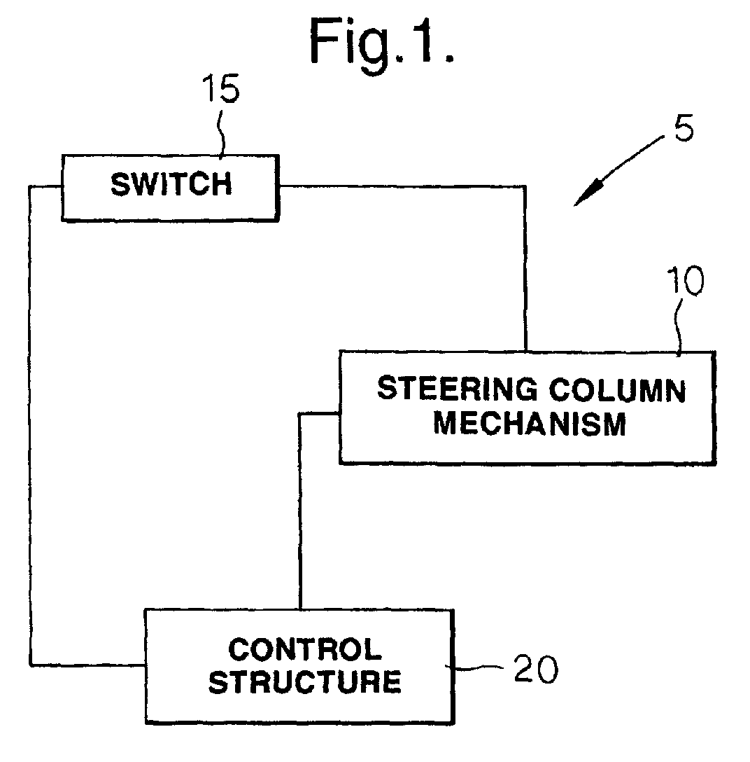
- the electrically actuated steering column system 5 includes an electrically actuated steering column mechanism 10 and a switch 15 interconnected with the electrically actuated steering column mechanism 10 for allowing movement of a steering column housing 30 by a driver.
- the electrically actuated steering column system 5 also includes appropriate electrical control structure 20 for regulating the electrically actuated steering column mechanism 10.
- the electrically actuated steering column system 5 allows a driver to activate the switch 15 and apply a force to initiate movement of the steering column housing 30. The driver may then deactivate the switch 15 to halt movement of the steering column housing 30.
- the switch 15 is positioned on a steering hand wheel 25 as shown in FIG. 5.
- the electrically actuated steering column mechanism 10 includes a steering column housing 30. At least one movement bracket 35 is attached to the housing 30, and allows for movement of the steering column housing 30 relative to a driver.
- a support plate 40 is associated with the at least one movement bracket 35. The support plate 40 includes a cam 45 for engaging and disengaging the electrically actuated steering column mechanism 10.
- a rake bolt 50 is positioned such that it intersects with the at least one movement bracket 35.
- the rake bolt 50 has first 55 and second 60 ends.
- An electric actuator 65 is attached to the rake bolt 50 at the first end 55 and allows for moving the rake bolt 50. Movement of the rake bolt 50 allows a switching action whereby movement of the steering column housing 30 relative to a driver is initiated and halted.
- the first embodiment of the electrically actuated steering column mechanism 10 is designed for use with a rake and telescoping steering column.
- the at least one movement bracket of the first embodiment preferably comprises a mounting bracket 85 and a rake bracket 90 both of which are attached to the steering column housing 30.
- the mounting bracket 85 is generally a U-shaped member attached at an underside of the steering column housing.
- the mounting bracket 85 has slots 95 formed on opposite sides 100. The slots 95 allow the rake bolt 50 to pass through.
- the electrically actuated steering column mechanism 10 of the first embodiment includes a second rake bracket 92 attached to the steering column housing 30 on an opposite side 94 of the steering column housing 30 relative to a first rake bracket 90 thereby creating a symmetrical orientation. In this manner, the steering column housing 30 can maintain a uniform collapse stroke during a crash.
- the electrically actuated steering column mechanism 10, of the first embodiment includes a cam insert 80 disposed about the rake bolt 50 to facilitate increasing or decreasing a compression force to allow for movement of the steering column housing 30 relative to a driver.
- a cam insert 80 disposed about the rake bolt 50 to facilitate increasing or decreasing a compression force to allow for movement of the steering column housing 30 relative to a driver.
- the cam 45 of the support plate 40 may be formed integrally with the support plate 40 or be a piece that is connected with the support plate 40.
- a bore 105 may be formed within the support plate 40 in which a cam 45 is press fit.
- the manner of forming the cam 45 in the support plate 40 is not critical and alternative means of forming cams within the support plate 40 can be utilized without departing from the inventive aspect of the mechanism.
- the support plate 40 also preferably includes a cam guide 110 attached therewith.
- the cam guide 110 aligns the cam insert 80 with the cam 45 formed in the support plate 40.
- the cam guide has a shape corresponding to the cam insert 80 to prevent misalignment of the cam insert 80 with the cam 45.
- the electrically actuated steering column mechanism of the first embodiment also includes an electric actuator 65 that comprises an electric motor assembly 115.
- the electric motor assembly 115 comprises an electric motor 120, gearing 125 for transferring the rotary motion of the electric motor 120, and a mounting rod 130 for attaching the electric motor assembly 115 to the support plate 40.
- the gearing 125 associated with the electric motor assembly 115 comprises a partial gear 135 that is meshed with a gear 140 that is connected to the electric motor 120.
- the first end 55 of the rake bolt 50 is connected to the partial gear 135 for providing movement to the rake bolt 50.
- a limiting switch 145 is associated with the partial gear 135 to stop rotation of the partial gear 135 corresponding to initiating and halting movement of the steering column housing 30 relative to a driver.
- the electric actuator 65 as described in the first embodiment need not be directly attached to the rake bolt 50, as described above.
- the actuator 65 can be placed at other positions on the steering column housing 30 and the rotary motion transmitted to the rake bolt 50 and the cam insert 80 through a belt and pulley drive, a chain and sprocket drive or a screw rod and crank without departing from the inventive aspect of the mechanism.
- the cam 45 and cam insert 80 may be replaced by a multiple lead screw rod that may be turned by the electric actuator 65 to clamp the mounting bracket 85 and increase or decrease the compression force as described above.
- the rake bolt 50 includes a locking portion 150 circumferentially disposed thereon for interacting with the mounting 85 and rake brackets 90, 92.
- two locking portions 150 are disposed about the rake bolt 50 to interact with the symmetrically positioned mounting bracket 85 and rake brackets 90 and 92, as previously described.
- the mounting bracket 85 includes slots 95 formed on opposite sides 100 of the mounting bracket, to allow for passage of the rake bolt 50.
- the slots in a preferred aspect, include serrations 79 formed along a bottom edge of the slot such that they engage with teeth 78 formed on the locking portion 150.
- the rake brackets 90, 92 also include serrations 96 formed on an edge of the slot, again to mesh with the teeth 78 formed on the locking portion 150 during a collision.
- the teeth 78 formed on the locking portion 150 and the serrations 79, 96 formed on the mounting 85 and rake brackets 90, 92 provide a positive locking feature designed to move the steering column housing 30 in a uniform manner along a collapse stroke, during a collision.
- the first end 55 of the rake bolt 50 may include a shaped portion 155 that mates with the electric motor assembly 115.
- the shaped portion 155 can be square, keyed, any other shape that is designed to mesh with the partial gear 135 of the electric motor assembly 115.
- a spring 165 associated with the support plate 40 that allows for movement of the electric motor assembly 115 corresponding to movement of the steering column housing 30. In this manner, the electric motor assembly 115 is allowed to move relative to the steering column housing 30 while maintaining a connection with the rake bolt 50.
- the spring 165 is attached at a first end with the support plate 40 and at a second end to the electric motor assembly 115.
- a positioning spring 70 may be disposed between the mounting bracket 85 and the steering column housing 30 for applying a constant biasing force that returns the steering column housing 30 to an initial position 75 when a force is not applied by the driver to move the steering column housing 30.
- a door switch as opposed to the switch 15, may be included in a driver door such that when a vehicle is shutoff and the driver opens a door to exit, the electrically actuated steering column mechanism 10 is initiated to allow movement of the steering column housing 30.
- the positioning spring 70 then applies a force to the rake bracket returning the steering column housing 30 to an initial position 75, as detailed above.
- the electrically actuated steering column mechanism 10 In use, as the switch 15 of the electrically actuated steering column system 5 is depressed by a driver, the electrically actuated steering column mechanism 10 allows movement of a steering column housing 30 relative to the driver. Electrical control structure 20 regulates the electrically actuated steering column mechanism 10 to initiate and halt movement of the steering column housing 30.
- the electric motor 120 of the electric motor assembly 115 turns a gear 140 that is meshed with a partial gear 135.
- the first end 55 of the rake bolt 50 is connected with the partial gear 135 such that the rake bolt 50 is turned in a rotary manner.
- the cam insert 80 disposed about the rake bolt 50 engages the cam 45 of the support plate 40 such that the compression force placed on the electrically actuated steering column mechanism 10 is decreased to allow movement of the steering column housing 30 relative to the driver.
- the control structure deactivates the electric motor 120 once rotation of the rake bolt 50 has sufficiently reduced the compression force to allow movement of the steering column housing 30.
- the control structure 20 again initiates the electric motor 120 turning the rake bolt 50 in an opposite direction to again apply a compression force to the electrically actuated steering column mechanism 10 such that movement of the steering column housing 30 relative to a driver is halted.
- a driver can simply depress a switch 15 thereby allowing movement of the steering column housing 30 without the use of a lever as is commonly utilized in the art.
- the at least one movement bracket 235 comprises a rake bracket 290 only.
- the support plate 240 of the second embodiment is attached to the rake bracket 290 and includes a cam 45 just as with the previously described first embodiment.
- a cam insert 80 is disposed over a rake bolt 50 to interact with the cam 45 to increase and decrease a compressive force, as previously described with reference to the first embodiment.
- the support plate 240 of the second embodiment includes a flange 245 that engages the rake bracket 290 such that the support plate 240 can move relative to the rake bracket 290.
- the second embodiment also includes an electric actuator 265 that comprises an electric motor assembly 270.
- the electric motor assembly 270 is similar in respect to that of the previously described first embodiment with the exception that the electric motor assembly 270 does not include a mounting rod, as the support plate 240 is attached to the rake bracket 290.
- the electric motor assembly 270 of the second embodiment otherwise operates in a similar fashion to that of the first embodiment previously described.
- the electric motor assembly of the second embodiment is however attached to the rake bracket 290 utilizing a motor mounting bracket 280.
- the motor mounting bracket 280 includes a C-shaped slot 282 that allows for the motor assembly to move while the motor mounting bracket 280 is permanently secured to a portion of the vehicle structure. In this manner, the motor assembly 270 is free-floating within the C-shaped slot to allow for movement of the rake bolt 50 within the slot 284 formed in the rake bracket 285.
Abstract
Description
- This invention relates to an adjustable steering column, and more particularly, to an electrically actuated steering column.
- Steering columns currently in production with both a rake and telescope feature generally use a lever to lock and unlock the mechanism allowing movement of the steering column. Often, the lever utilized to unlock and lock the adjustment mechanism is placed on an underside of the steering column and is cumbersome to adjust by a driver.
- Various positions of the lever currently used today are also necessary to accommodate left-hand and right-hand drivers. Often, because of the awkward position of such a lever, drivers may not lock the lever in position to maintain a position of a steering column.
- There is, therefore, a need in the art for an electrically actuated steering column mechanism that will eliminate the need for a mechanical lever to unlock and lock a steering column.
- An electrically actuated steering column system that includes an electrically actuated steering column mechanism. The mechanism is interconnected with a switch that may be toggled by a driver to allow movement of a steering column housing. There is also included appropriate electrical control structure for regulating the electrically actuated steering column mechanism. The electrically actuated steering column system allows a driver to activate the switch and apply a force to initiate movement of the steering column housing and then deactivate the switch to halt movement of the steering column housing.
- The electrically actuated steering column mechanism includes a steering column housing, at least one movement bracket attached to the steering column housing, and a support plate associated with the at least one movement bracket. The support plate includes a cam. A rake bolt having first and second ends is positioned to intersect with the at least one movement bracket. There is also included an electrical actuator attached to the rake bolt at the first end allowing movement of the rake bolt to initiate a switching action whereby movement of a steering column housing relative to the driver is initiated and halted.
- These and other features and advantages of the present invention will become more readily appreciated when considered in connection with the following detailed description and appended drawings, where:
- FIG. 1 is a diagram detailing the electrically actuated steering column system of the present invention;
- FIG. 2 is an exploded perspective view detailing a first embodiment of an electrically actuated steering column mechanism of the present invention;
- FIG. 3 is an assembled perspective view of the first embodiment of the electrically actuated steering column mechanism of the present invention;
- FIG. 4 is an exploded perspective view detailing a second embodiment of the electrically actuated steering column mechanism of the present invention;
- FIG. 5 is a perspective view of a steering hand wheel detailing locations for the switch of the electrically actuated steering column system of the present invention.
-
- With reference to FIG. 1, there is shown an electrically actuated
steering column system 5 according to the present invention. The electrically actuatedsteering column system 5 includes an electrically actuatedsteering column mechanism 10 and aswitch 15 interconnected with the electrically actuatedsteering column mechanism 10 for allowing movement of asteering column housing 30 by a driver. The electrically actuatedsteering column system 5 also includes appropriateelectrical control structure 20 for regulating the electrically actuatedsteering column mechanism 10. The electrically actuatedsteering column system 5 allows a driver to activate theswitch 15 and apply a force to initiate movement of thesteering column housing 30. The driver may then deactivate theswitch 15 to halt movement of thesteering column housing 30. In a preferred embodiment, theswitch 15 is positioned on asteering hand wheel 25 as shown in FIG. 5. - With reference to FIGS. 2 and 3, there is shown a first embodiment of the electrically actuated
steering column mechanism 10 of the present invention. The first embodiment is designed for use in a steering column that has the ability to be adjusted in a raking and telescoping manner. The electrically actuatedsteering column mechanism 10 includes asteering column housing 30. At least onemovement bracket 35 is attached to thehousing 30, and allows for movement of thesteering column housing 30 relative to a driver. Asupport plate 40 is associated with the at least onemovement bracket 35. Thesupport plate 40 includes acam 45 for engaging and disengaging the electrically actuatedsteering column mechanism 10. Arake bolt 50 is positioned such that it intersects with the at least onemovement bracket 35. Therake bolt 50 has first 55 and second 60 ends. Anelectric actuator 65 is attached to therake bolt 50 at thefirst end 55 and allows for moving therake bolt 50. Movement of therake bolt 50 allows a switching action whereby movement of thesteering column housing 30 relative to a driver is initiated and halted. - As stated above, the first embodiment of the electrically actuated
steering column mechanism 10 is designed for use with a rake and telescoping steering column. The at least one movement bracket of the first embodiment preferably comprises amounting bracket 85 and arake bracket 90 both of which are attached to thesteering column housing 30. Themounting bracket 85 is generally a U-shaped member attached at an underside of the steering column housing. Themounting bracket 85 hasslots 95 formed on opposite sides 100. Theslots 95 allow therake bolt 50 to pass through. The electrically actuatedsteering column mechanism 10 of the first embodiment includes asecond rake bracket 92 attached to thesteering column housing 30 on anopposite side 94 of thesteering column housing 30 relative to afirst rake bracket 90 thereby creating a symmetrical orientation. In this manner, thesteering column housing 30 can maintain a uniform collapse stroke during a crash. - The electrically actuated
steering column mechanism 10, of the first embodiment includes acam insert 80 disposed about therake bolt 50 to facilitate increasing or decreasing a compression force to allow for movement of thesteering column housing 30 relative to a driver. A more detailed description of the interaction of therake bolt 50 andcam 45 will be discussed below. - The
cam 45 of thesupport plate 40 may be formed integrally with thesupport plate 40 or be a piece that is connected with thesupport plate 40. For example, abore 105 may be formed within thesupport plate 40 in which acam 45 is press fit. The manner of forming thecam 45 in thesupport plate 40 is not critical and alternative means of forming cams within thesupport plate 40 can be utilized without departing from the inventive aspect of the mechanism. Thesupport plate 40 also preferably includes acam guide 110 attached therewith. Thecam guide 110 aligns thecam insert 80 with thecam 45 formed in thesupport plate 40. As can be seen in FIG. 2, the cam guide has a shape corresponding to thecam insert 80 to prevent misalignment of thecam insert 80 with thecam 45. - The electrically actuated steering column mechanism of the first embodiment also includes an
electric actuator 65 that comprises anelectric motor assembly 115. Theelectric motor assembly 115 comprises anelectric motor 120, gearing 125 for transferring the rotary motion of theelectric motor 120, and amounting rod 130 for attaching theelectric motor assembly 115 to thesupport plate 40. Thegearing 125 associated with theelectric motor assembly 115 comprises apartial gear 135 that is meshed with agear 140 that is connected to theelectric motor 120. Thefirst end 55 of therake bolt 50 is connected to thepartial gear 135 for providing movement to therake bolt 50. Alimiting switch 145 is associated with thepartial gear 135 to stop rotation of thepartial gear 135 corresponding to initiating and halting movement of thesteering column housing 30 relative to a driver. - The
electric actuator 65, as described in the first embodiment need not be directly attached to therake bolt 50, as described above. Theactuator 65 can be placed at other positions on the steering column housing 30 and the rotary motion transmitted to therake bolt 50 and the cam insert 80 through a belt and pulley drive, a chain and sprocket drive or a screw rod and crank without departing from the inventive aspect of the mechanism. Also, thecam 45 andcam insert 80 may be replaced by a multiple lead screw rod that may be turned by theelectric actuator 65 to clamp themounting bracket 85 and increase or decrease the compression force as described above. - In a preferred aspect of the present invention, the
rake bolt 50 includes alocking portion 150 circumferentially disposed thereon for interacting with the mounting 85 andrake brackets portions 150 are disposed about therake bolt 50 to interact with the symmetrically positioned mountingbracket 85 and rakebrackets bracket 85 includesslots 95 formed on opposite sides 100 of the mounting bracket, to allow for passage of therake bolt 50. The slots, in a preferred aspect, includeserrations 79 formed along a bottom edge of the slot such that they engage with teeth 78 formed on the lockingportion 150. Therake brackets serrations 96 formed on an edge of the slot, again to mesh with the teeth 78 formed on the lockingportion 150 during a collision. The teeth 78 formed on the lockingportion 150 and theserrations brackets steering column housing 30 in a uniform manner along a collapse stroke, during a collision. Thefirst end 55 of therake bolt 50 may include a shapedportion 155 that mates with theelectric motor assembly 115. The shapedportion 155 can be square, keyed, any other shape that is designed to mesh with thepartial gear 135 of theelectric motor assembly 115. - As another aspect of the first embodiment of the electrically actuated
steering column mechanism 10 of the present invention, there may be included a spring 165 associated with thesupport plate 40 that allows for movement of theelectric motor assembly 115 corresponding to movement of thesteering column housing 30. In this manner, theelectric motor assembly 115 is allowed to move relative to thesteering column housing 30 while maintaining a connection with therake bolt 50. The spring 165 is attached at a first end with thesupport plate 40 and at a second end to theelectric motor assembly 115. - In another aspect of the first embodiment of the present invention, a
positioning spring 70 may be disposed between the mountingbracket 85 and thesteering column housing 30 for applying a constant biasing force that returns thesteering column housing 30 to an initial position 75 when a force is not applied by the driver to move thesteering column housing 30. In this manner, when the electrically actuated steering column mechanism is initiated to allow movement of thesteering column housing 30, the default position of fully telescoped in the most upward rake position will allow a driver to exit a vehicle without having to apply a force to thesteering column housing 30. - As described above with reference to the electrically actuated
steering column system 5, a door switch, as opposed to theswitch 15, may be included in a driver door such that when a vehicle is shutoff and the driver opens a door to exit, the electrically actuatedsteering column mechanism 10 is initiated to allow movement of thesteering column housing 30. Thepositioning spring 70 then applies a force to the rake bracket returning thesteering column housing 30 to an initial position 75, as detailed above. - In use, as the
switch 15 of the electrically actuatedsteering column system 5 is depressed by a driver, the electrically actuatedsteering column mechanism 10 allows movement of asteering column housing 30 relative to the driver.Electrical control structure 20 regulates the electrically actuatedsteering column mechanism 10 to initiate and halt movement of thesteering column housing 30. - Specifically, when the
switch 15 is depressed by a driver, theelectric motor 120 of theelectric motor assembly 115 turns agear 140 that is meshed with apartial gear 135. Thefirst end 55 of therake bolt 50 is connected with thepartial gear 135 such that therake bolt 50 is turned in a rotary manner. Thecam insert 80 disposed about therake bolt 50 engages thecam 45 of thesupport plate 40 such that the compression force placed on the electrically actuatedsteering column mechanism 10 is decreased to allow movement of thesteering column housing 30 relative to the driver. The control structure deactivates theelectric motor 120 once rotation of therake bolt 50 has sufficiently reduced the compression force to allow movement of thesteering column housing 30. When theswitch 15 is released by the driver, thecontrol structure 20 again initiates theelectric motor 120 turning therake bolt 50 in an opposite direction to again apply a compression force to the electrically actuatedsteering column mechanism 10 such that movement of thesteering column housing 30 relative to a driver is halted. In this manner, a driver can simply depress aswitch 15 thereby allowing movement of thesteering column housing 30 without the use of a lever as is commonly utilized in the art. - With reference to FIG. 4, there is shown a second embodiment of the electrically actuated
steering column mechanism 10 of the present invention. The second embodiment includes a design for a steering column that is adjustable only in a raking manner and does not include a telescoping feature. Therefore, the at least onemovement bracket 235 comprises arake bracket 290 only. Thesupport plate 240 of the second embodiment is attached to therake bracket 290 and includes acam 45 just as with the previously described first embodiment. Again, acam insert 80 is disposed over arake bolt 50 to interact with thecam 45 to increase and decrease a compressive force, as previously described with reference to the first embodiment. With reference to FIG. 4, it can be seen that thesupport plate 240 of the second embodiment includes aflange 245 that engages therake bracket 290 such that thesupport plate 240 can move relative to therake bracket 290. The second embodiment also includes anelectric actuator 265 that comprises anelectric motor assembly 270. Theelectric motor assembly 270 is similar in respect to that of the previously described first embodiment with the exception that theelectric motor assembly 270 does not include a mounting rod, as thesupport plate 240 is attached to therake bracket 290. Theelectric motor assembly 270 of the second embodiment otherwise operates in a similar fashion to that of the first embodiment previously described. The electric motor assembly of the second embodiment, is however attached to therake bracket 290 utilizing amotor mounting bracket 280. Themotor mounting bracket 280 includes a C-shapedslot 282 that allows for the motor assembly to move while themotor mounting bracket 280 is permanently secured to a portion of the vehicle structure. In this manner, themotor assembly 270 is free-floating within the C-shaped slot to allow for movement of therake bolt 50 within theslot 284 formed in the rake bracket 285. - While preferred embodiments are disclosed, a worker in this art would understand that various modifications were to come within the scope of the invention. Thus, the following claims should be studied to determine the scope and content of this invention.
Claims (29)
- An electrically actuated steering column mechanism (10) comprising:a steering column housing (30);at least one movement bracket (35) attached to the steering column housing (30);a support plate (40) associated with the at least one movement bracket (35), the support plate (40) including a cam (45);a rake bolt (50) positioned to intersect with the at least one movement bracket (35), the rake bolt (50) having first (55) and second ends (60);an electric actuator (65) attached to the rake bolt (50) at the first end (55), the electric actuator (65) moving the rake bolt (50) allowing a switching action whereby movement of the steering column housing (30) relative to a driver is initiated and halted.
- The electrically actuated steering column mechanism (10) of Claim 1 further including a cam insert (80) disposed about the rake bolt (50) and interacting with the cam (45), facilitating increasing or decreasing a compression force to allow movement of the steering column housing (30) relative to a driver.
- The electrically actuated steering column mechanism (10) of Claim 1 wherein the at least one movement bracket (35) comprises a mounting bracket (85) and a rake bracket (90) attached to the steering column housing (30).
- The electrically actuated steering column mechanism (10) of Claim 3 wherein the mounting bracket (85) and rake bracket (90) include slots (95) formed therein for allowing the rake bolt (50) to pass through.
- The electrically actuated steering column mechanism (10) of Claim 3 wherein the mounting bracket (85) has a symmetrical shape including slots (95) formed on opposite sides (100) thereof, allowing the rake bolt (50) to pass through.
- The electrically actuated steering column mechanism (10) of Claim 1 including a second rake bracket (92) attached to the steering column housing (30) on an opposite side (94) of the steering column housing (30) relative to a first rake bracket (90), creating a symmetrical orientation.
- The electrically actuated steering column mechanism (10) of Claim 1 wherein the cam (45) is formed integrally with the support plate (40).
- The electrically actuated steering column mechanism (10) of Claim 1 wherein the cam (45) is press fit into a bore (105) formed within the support plate (40).
- The electrically actuated steering column mechanism (10) of Claim 1 wherein the support plate (40) includes a cam guide (110) associated therewith.
- The electrically actuated steering column mechanism (10) of Claim 1 wherein the electric actuator (65) comprises an electric motor assembly (115).
- The electrically actuated steering column mechanism (10) of Claim 10 wherein the electric motor assembly (115) comprises an electric motor (120), gearing (125) for transferring the rotary motion of the electric motor (120), and a mounting rod (130) for attaching the electric motor assembly (115) to the support plate (40).
- The electrically actuated steering column mechanism (10) of Claim 11 wherein the gearing (125) comprises a partial gear (135) meshed with a gear (140) connected to the electric motor (120).
- The electrically actuated steering column mechanism (10) of Claim 12 wherein the rake bolt (50) is connected to the partial gear (135) for providing movement to the rake bolt (50).
- The electrically actuated steering column mechanism (10) of Claim 10 wherein the motor assembly further includes a limiting switch (145) associated with the partial gear (135) for stopping rotation of the partial gear (135) corresponding to initiating and halting movement of the steering column housing (30) relative to a driver.
- The electrically actuated steering column mechanism (10) of Claim 3 wherein the rake bolt (50) includes a locking portion (150) circumferentially disposed thereon for interacting with the mounting (85) and rake brackets (90, 92).
- The electrically actuated steering column mechanism (10) of Claim 6 wherein two locking portions (150) are disposed about the rake bolt (50) to interact with the symmetrically positioned mounting bracket (85) and rake brackets (90, 92).
- The electrically actuated steering column mechanism (10) of Claim 10 wherein the first end (55) of the rake bolt (50) includes a shaped portion (155) for mating with the electric motor assembly (115).
- The electrically actuated steering column mechanism (10) of Claim 11 wherein the support plate (40) includes a bore (160) formed therein corresponding to a location of the mounting rod (130) of the electric motor assembly (115).
- The electrically actuated steering column mechanism (10) of Claim 11 further including a spring (165) associated with the support plate (40) allowing for movement of the electric motor assembly (115) corresponding to movement of the steering column housing (30).
- The electrically actuated steering column mechanism (10) of Claim 1 further including a positioning spring (70) positioned between the rake bracket (90) and the steering column housing (30) for applying a constant biasing force that returns the steering column housing (30) to an initial position (75) when a force is not applied by the driver to move the steering column housing (30).
- The electrically actuated steering column mechanism (10) of Claim 1 wherein the at least one movement bracket (235) comprises a rake bracket (290).
- The electrically actuated steering column mechanism (10) of Claim 21 wherein the support plate (240) is attached to the rake bracket (290).
- The electrically actuated steering column mechanism (10) of Claim 21 wherein the electric actuator (265) comprises an electric motor assembly (270).
- The electrically actuated steering column mechanism (10) of Claim 23 further including a motor mounting bracket (280) for attaching the electric motor assembly (270) to the rake bracket (290).
- An electrically actuated steering column system (5) comprising:an electrically actuated steering column mechanism (10);a switch (15) interconnected with the electrically actuated steering column mechanism (10) for allowing movement of a steering column housing (30) by a driver;electrical control structure (20) for regulating the electrically actuated steering column mechanism (10);the electrically actuated steering column system (5) allowing a driver to activate the switch (15) and apply a force to initiate movement of the steering column housing (30) and deactivate the switch (15) to halt movement of the steering column housing (30).
- The electrically actuated steering column system (5) of Claim 25 wherein the switch (15) is positioned on a steering hand wheel (25).
- The electrically actuated steering column system (5) of Claim 25 wherein the electrically actuated steering column mechanism (10) comprises:a steering column housing (30);at least one movement bracket (35) attached to the steering column housing (30);a support plate (40) associated with the at least one movement bracket (35), the support plate (40) including a cam (45);a rake bolt (50) positioned to intersect with the at least one mounting bracket (35), the rake bolt (50) having first (55) and second ends (60);an electric actuator (65) attached to the rake bolt (50) at the first end (55), the electric actuator (65) moving the rake bolt (50) allowing a switching action whereby movement of the steering column housing (30) relative to a driver is initiated and halted.
- The electrically actuated steering column system (5) of Claim 27 wherein the electrically actuated steering column mechanism (10) further includes a positioning spring (70) positioned between the rake bracket (90) and the steering column housing (30) for applying a constant biasing force that returns the steering column housing (30) to an initial position (75) when a force is not applied by the driver to move the steering column housing (30).
- The electrically actuated steering column system (5) of Claim 28 further including a switch (78) associated with a driver door whereby opening the driver door initiates movement of the rake bolt (50) allowing movement of the steering column housing (30) and wherein the positioning spring (70) moves the steering column housing (30) to the initial position (75).
Applications Claiming Priority (2)
| Application Number | Priority Date | Filing Date | Title |
|---|---|---|---|
| US184695 | 2002-06-27 | ||
| US10/184,695 US7055860B2 (en) | 2002-06-27 | 2002-06-27 | Electrically actuated steering column mechanism |
Publications (2)
| Publication Number | Publication Date |
|---|---|
| EP1375296A1 true EP1375296A1 (en) | 2004-01-02 |
| EP1375296B1 EP1375296B1 (en) | 2006-06-07 |
Family
ID=29717972
Family Applications (1)
| Application Number | Title | Priority Date | Filing Date |
|---|---|---|---|
| EP03076818A Expired - Fee Related EP1375296B1 (en) | 2002-06-27 | 2003-06-12 | Electrically actuated steering column mechanism |
Country Status (3)
| Country | Link |
|---|---|
| US (1) | US7055860B2 (en) |
| EP (1) | EP1375296B1 (en) |
| DE (1) | DE60305795T2 (en) |
Cited By (8)
| Publication number | Priority date | Publication date | Assignee | Title |
|---|---|---|---|---|
| FR2862037A1 (en) * | 2003-11-12 | 2005-05-13 | Nacam France Sas | ELECTRICAL CLAMPING OF AN ADJUSTABLE STEERING COLUMN OF A MOTOR VEHICLE |
| EP1612121A1 (en) * | 2004-07-01 | 2006-01-04 | Delphi Technologies, Inc. | Electrically actuated steering column mechanism |
| EP1714849A2 (en) * | 2005-04-19 | 2006-10-25 | Delphi Technologies, Inc. | Steering column with rake and telescope adjustment |
| WO2008152253A1 (en) * | 2007-06-12 | 2008-12-18 | Zf Systemes De Direction Nacam, S.A.S. | Electric clamping device for an adjustable motor vehicle steering column |
| EP2113441A3 (en) * | 2008-05-02 | 2010-01-20 | Delphi Technologies, Inc. | Electric steering column clamping device with single direction actuator travel |
| FR2947233A1 (en) * | 2009-06-30 | 2010-12-31 | Zf Systemes De Direction Nacam Sas | ELECTRIC LOCKING SYSTEM OF A STEERING COLUMN AND STEERING COLUMN COMPRISING SUCH A LATCHING SYSTEM |
| US7861615B2 (en) | 2005-04-19 | 2011-01-04 | Gm Global Technology Operations, Inc. | Adjustable steering column assembly |
| US8985628B2 (en) | 2011-08-16 | 2015-03-24 | GM Global Technology Operations LLC | Adjusting device |
Families Citing this family (10)
| Publication number | Priority date | Publication date | Assignee | Title |
|---|---|---|---|---|
| US20060266151A1 (en) * | 2005-05-25 | 2006-11-30 | Admiral Tool And Manufacturing Company, Inc. | Power adjust tilt-telescope steering column |
| US7640824B2 (en) * | 2006-09-13 | 2010-01-05 | Gm Global Technology Operations, Inc. | Central lock device of an adjustable steering column assembly |
| US8313120B2 (en) * | 2006-12-31 | 2012-11-20 | Honda Motor Co., Ltd. | Multi-piece steering-column cover |
| US7621197B2 (en) * | 2007-03-21 | 2009-11-24 | Gm Global Technology Operations, Inc. | Releasable push/pull lock device of an adjustable steering column assembly |
| US7732364B2 (en) * | 2007-12-28 | 2010-06-08 | Chevron U.S.A. Inc. | Process for ionic liquid catalyst regeneration |
| KR101143683B1 (en) | 2008-03-18 | 2012-05-09 | 주식회사 만도 | The Button Type Steering Apparatus for Vehicle |
| US8359945B2 (en) * | 2008-04-23 | 2013-01-29 | Steering Solutions Ip Holding Corporation | Adjustable steering column assembly |
| US9751553B2 (en) | 2014-02-24 | 2017-09-05 | Steering Solutions Ip Holding Corporation | Power rake and telescope dynamic travel limits |
| DE102015007784B4 (en) | 2015-06-19 | 2020-02-13 | Thyssenkrupp Ag | Steering column with electro-mechanical fixing device |
| US10228047B2 (en) | 2016-06-17 | 2019-03-12 | Robert Bosch Llc | Actuator for providing relative motion between two points |
Citations (3)
| Publication number | Priority date | Publication date | Assignee | Title |
|---|---|---|---|---|
| US4752085A (en) * | 1985-10-14 | 1988-06-21 | Fuji Kiko Company, Limited | Powered tilt steering arrangement |
| JPH03272528A (en) * | 1990-03-22 | 1991-12-04 | Matsushita Electric Ind Co Ltd | Steering wheel switch for vehicle |
| US6237438B1 (en) * | 1998-07-13 | 2001-05-29 | Lemfördes Nacam SA | Electrically controlled clamping system |
Family Cites Families (29)
| Publication number | Priority date | Publication date | Assignee | Title |
|---|---|---|---|---|
| US3978740A (en) * | 1975-06-02 | 1976-09-07 | International Harvester Company | Adjustable steering column |
| US4244236A (en) * | 1979-05-29 | 1981-01-13 | International Harvester Company | Tilt steering column mechanism |
| ES494694A0 (en) * | 1980-07-30 | 1981-04-01 | Bendiberica Sa | IMPROVEMENTS IN MECHANISMS FOR ADJUSTING THE POSITION OF THE STEERING WHEEL IN VEHICLES |
| DE3510311A1 (en) * | 1985-03-22 | 1986-09-25 | Klöckner-Humboldt-Deutz AG, 5000 Köln | DEVICE FOR VERTICAL AND AXIAL ADJUSTMENT OF THE POSITION OF A STEERING WHEEL |
| SE457871B (en) * | 1987-06-15 | 1989-02-06 | Volvo Ab | STEERING DEVICE FOR MOTOR VEHICLE |
| DE3914608C1 (en) * | 1989-05-03 | 1990-10-31 | Lemfoerder Metallwaren Ag, 2844 Lemfoerde, De | |
| SE465563B (en) * | 1989-10-31 | 1991-09-30 | Volvo Ab | ADJUSTABLE VEHICLE |
| US5485376A (en) * | 1991-06-14 | 1996-01-16 | Nissan Motor Co., Ltd. | Steering wheel posture control system |
| DE4235588A1 (en) * | 1992-10-22 | 1994-04-28 | Stabilus Gmbh | Hydropneumatic adjustment element |
| GB2281539A (en) * | 1993-09-01 | 1995-03-08 | Torrington Co | Adjustable vehicle steering column assembly |
| SE502558C2 (en) * | 1994-03-09 | 1995-11-13 | Fuji Autotech Ab | Telescopic and swivel steering column bracket |
| US5562306A (en) * | 1994-03-18 | 1996-10-08 | Dr. Ing. H.C.F. Porsche Ag | Adjustable steering device |
| US5722299A (en) * | 1994-06-30 | 1998-03-03 | Fuji Kiko Co., Ltd. | Adjustable steering column assembly for a vehicle |
| US5520416A (en) * | 1994-10-03 | 1996-05-28 | Ford Motor Company | Power tilt, telescoping and internally collapsible steering column |
| DE29521414U1 (en) * | 1995-10-12 | 1997-02-27 | Vdo Schindling | Motor vehicle with a position-changing steering wheel and a position-changing instrument panel |
| US5820163A (en) * | 1996-07-08 | 1998-10-13 | Ford Global Technologies, Inc. | Tilting, telescoping and energy absorbing steering column |
| US5829311A (en) * | 1996-08-15 | 1998-11-03 | Roberson; Jarried E. | Motorized tilt steering device |
| US5787759A (en) * | 1997-02-11 | 1998-08-04 | General Motors Corporation | Position control apparatus for steering column |
| US6189405B1 (en) * | 1998-04-30 | 2001-02-20 | Kabushiki Kaisha Yamada Seisa Kusho | Position adjusting device for steering wheels |
| US6139057A (en) * | 1999-02-04 | 2000-10-31 | Delphi Technologies, Inc. | Position control apparatus for steering column |
| US6419269B1 (en) * | 1999-09-20 | 2002-07-16 | Delphi Technologies | Locking system for adjustable position steering column |
| US6390505B1 (en) * | 2000-04-19 | 2002-05-21 | International Truck Intellectual Property Company, L.L.C. | Steering column adjustment system using force feedback system |
| JP3431886B2 (en) * | 2000-07-07 | 2003-07-28 | 株式会社山田製作所 | Steering position adjustment device |
| DE10039794A1 (en) * | 2000-08-16 | 2002-02-28 | Daimler Chrysler Ag | Position adjustment device for a steering column |
| US6659504B2 (en) * | 2001-05-18 | 2003-12-09 | Delphi Technologies, Inc. | Steering column for a vehicle |
| DE10152807A1 (en) * | 2001-10-25 | 2003-05-15 | Daimler Chrysler Ag | Clamp mechanism for an adjustable steering column |
| US6666478B2 (en) * | 2002-05-01 | 2003-12-23 | Trw Inc. | Steering column |
| US6748774B2 (en) * | 2002-10-15 | 2004-06-15 | Delphi Technologies, Inc. | Forward firing shaft lock mechanism |
| FR2862037B1 (en) * | 2003-11-12 | 2007-11-16 | Nacam France Sas | ELECTRICAL CLAMPING OF AN ADJUSTABLE STEERING COLUMN OF A MOTOR VEHICLE |
-
2002
- 2002-06-27 US US10/184,695 patent/US7055860B2/en not_active Expired - Lifetime
-
2003
- 2003-06-12 EP EP03076818A patent/EP1375296B1/en not_active Expired - Fee Related
- 2003-06-12 DE DE60305795T patent/DE60305795T2/en not_active Expired - Lifetime
Patent Citations (3)
| Publication number | Priority date | Publication date | Assignee | Title |
|---|---|---|---|---|
| US4752085A (en) * | 1985-10-14 | 1988-06-21 | Fuji Kiko Company, Limited | Powered tilt steering arrangement |
| JPH03272528A (en) * | 1990-03-22 | 1991-12-04 | Matsushita Electric Ind Co Ltd | Steering wheel switch for vehicle |
| US6237438B1 (en) * | 1998-07-13 | 2001-05-29 | Lemfördes Nacam SA | Electrically controlled clamping system |
Non-Patent Citations (1)
| Title |
|---|
| PATENT ABSTRACTS OF JAPAN vol. 016, no. 091 (E - 1174) 5 March 1992 (1992-03-05) * |
Cited By (21)
| Publication number | Priority date | Publication date | Assignee | Title |
|---|---|---|---|---|
| US7331608B2 (en) | 2002-06-27 | 2008-02-19 | Delphi Technologies, Inc. | Electrically actuated steering column mechanism |
| US7367246B2 (en) | 2003-11-12 | 2008-05-06 | Nacam France S.A.S. | Adjustable steering column including electrically-operable locking means |
| FR2862037A1 (en) * | 2003-11-12 | 2005-05-13 | Nacam France Sas | ELECTRICAL CLAMPING OF AN ADJUSTABLE STEERING COLUMN OF A MOTOR VEHICLE |
| EP1612121A1 (en) * | 2004-07-01 | 2006-01-04 | Delphi Technologies, Inc. | Electrically actuated steering column mechanism |
| EP1714849A3 (en) * | 2005-04-19 | 2011-01-19 | GM Global Technology Operations, Inc. | Steering column with rake and telescope adjustment |
| EP1714849A2 (en) * | 2005-04-19 | 2006-10-25 | Delphi Technologies, Inc. | Steering column with rake and telescope adjustment |
| US8220355B2 (en) | 2005-04-19 | 2012-07-17 | Steering Solutions Ip Holding Corporation | Electric steering column lock with single direction actuator travel |
| US8201475B2 (en) | 2005-04-19 | 2012-06-19 | Steering Solutions Ip Holding Corporation | Steering column with rake and telescope adjustment |
| US8056437B2 (en) | 2005-04-19 | 2011-11-15 | Nexteer (Beijing) Technology Co., Ltd. | Electric steering column lock with single direction actuator travel |
| US7861615B2 (en) | 2005-04-19 | 2011-01-04 | Gm Global Technology Operations, Inc. | Adjustable steering column assembly |
| WO2008152253A1 (en) * | 2007-06-12 | 2008-12-18 | Zf Systemes De Direction Nacam, S.A.S. | Electric clamping device for an adjustable motor vehicle steering column |
| CN101765533B (en) * | 2007-06-12 | 2011-12-14 | 采埃孚转向机系统纳凯姆联合股份公司 | Electric clamping device for an adjustable motor vehicle steering column |
| FR2917362A1 (en) * | 2007-06-12 | 2008-12-19 | Zf Systemes De Direction Nacam Sas | DEVICE FOR ELECTRICALLY CLAMPING AN ADJUSTABLE STEERING COLUMN OF A MOTOR VEHICLE |
| US8316737B2 (en) | 2007-06-12 | 2012-11-27 | Zf Systems De Direction Nacam, S.A.S. | Electric clamping device for an adjustable motor vehicle steering column |
| EP2113441A3 (en) * | 2008-05-02 | 2010-01-20 | Delphi Technologies, Inc. | Electric steering column clamping device with single direction actuator travel |
| WO2011001092A2 (en) | 2009-06-30 | 2011-01-06 | Zf Systemes De Direction Nacam S.A.S. | System for electrically locking a steering column, and steering column including such a locking system |
| WO2011001092A3 (en) * | 2009-06-30 | 2011-02-24 | Zf Systemes De Direction Nacam S.A.S. | System for electrically locking a steering column, and steering column including such a locking system |
| FR2947233A1 (en) * | 2009-06-30 | 2010-12-31 | Zf Systemes De Direction Nacam Sas | ELECTRIC LOCKING SYSTEM OF A STEERING COLUMN AND STEERING COLUMN COMPRISING SUCH A LATCHING SYSTEM |
| US8910540B2 (en) | 2009-06-30 | 2014-12-16 | Zf Systemes De Direction Nacam S.A.S. | System for electrically locking a steering column, and steering column including such a locking system |
| US9168944B2 (en) | 2009-06-30 | 2015-10-27 | Robert Bosch Automotive Steering Vendome | System for electrically locking a steering column, and steering column including such a locking system |
| US8985628B2 (en) | 2011-08-16 | 2015-03-24 | GM Global Technology Operations LLC | Adjusting device |
Also Published As
| Publication number | Publication date |
|---|---|
| EP1375296B1 (en) | 2006-06-07 |
| DE60305795D1 (en) | 2006-07-20 |
| DE60305795T2 (en) | 2007-05-24 |
| US7055860B2 (en) | 2006-06-06 |
| US20040000779A1 (en) | 2004-01-01 |
Similar Documents
| Publication | Publication Date | Title |
|---|---|---|
| EP1375296B1 (en) | Electrically actuated steering column mechanism | |
| US7331608B2 (en) | Electrically actuated steering column mechanism | |
| US7178422B2 (en) | Electrical tilt and telescope locking mechanism | |
| US7533594B2 (en) | Position control apparatus for steering column | |
| US10829144B2 (en) | Steering column comprising an adaptive energy absorption device for a motor vehicle | |
| US20180037250A1 (en) | Steering column for a motor vehicle | |
| US20080284150A1 (en) | Steering system | |
| US5531317A (en) | Tilt-type steering column device | |
| US20090282945A1 (en) | Dual on-center column lock mechanism | |
| US20090120229A1 (en) | Steering column device | |
| US10843721B2 (en) | Steering column comprising an energy absorption device for a motor vehicle | |
| US7503234B2 (en) | One lever tilt and telescope mechanism | |
| EP1714849A3 (en) | Steering column with rake and telescope adjustment | |
| EP2196348A1 (en) | Driving pedal module | |
| US7587959B2 (en) | Steering column assembly | |
| EP3067248B1 (en) | Steering apparatus | |
| EP1911657A2 (en) | Steering column assembly for a vehicle | |
| JP2022548443A (en) | Steering column anti-rotation device | |
| KR19980033017A (en) | Adjustable Handle Shaft Fasteners | |
| US11697447B2 (en) | Steering column positive lock drive mechanism | |
| EP1365303B1 (en) | Pedal adjustment mechanism | |
| US11524713B2 (en) | Steering column for a motor vehicle | |
| KR20140009745A (en) | Latching apparatus of steering column for vehicle | |
| US20050115355A1 (en) | Pedal | |
| US11845487B2 (en) | Steering column breakaway and energy absorption apparatus |
Legal Events
| Date | Code | Title | Description |
|---|---|---|---|
| PUAI | Public reference made under article 153(3) epc to a published international application that has entered the european phase |
Free format text: ORIGINAL CODE: 0009012 |
|
| AK | Designated contracting states |
Kind code of ref document: A1 Designated state(s): AT BE BG CH CY CZ DE DK EE ES FI FR GB GR HU IE IT LI LU MC NL PT RO SE SI SK TR |
|
| AX | Request for extension of the european patent |
Extension state: AL LT LV MK |
|
| 17P | Request for examination filed |
Effective date: 20040702 |
|
| AKX | Designation fees paid |
Designated state(s): DE FR GB IT |
|
| 17Q | First examination report despatched |
Effective date: 20050601 |
|
| GRAP | Despatch of communication of intention to grant a patent |
Free format text: ORIGINAL CODE: EPIDOSNIGR1 |
|
| GRAS | Grant fee paid |
Free format text: ORIGINAL CODE: EPIDOSNIGR3 |
|
| GRAA | (expected) grant |
Free format text: ORIGINAL CODE: 0009210 |
|
| AK | Designated contracting states |
Kind code of ref document: B1 Designated state(s): DE FR GB IT |
|
| REG | Reference to a national code |
Ref country code: GB Ref legal event code: FG4D |
|
| REF | Corresponds to: |
Ref document number: 60305795 Country of ref document: DE Date of ref document: 20060720 Kind code of ref document: P |
|
| ET | Fr: translation filed | ||
| PLBE | No opposition filed within time limit |
Free format text: ORIGINAL CODE: 0009261 |
|
| STAA | Information on the status of an ep patent application or granted ep patent |
Free format text: STATUS: NO OPPOSITION FILED WITHIN TIME LIMIT |
|
| 26N | No opposition filed |
Effective date: 20070308 |
|
| PGFP | Annual fee paid to national office [announced via postgrant information from national office to epo] |
Ref country code: FR Payment date: 20100709 Year of fee payment: 8 |
|
| REG | Reference to a national code |
Ref country code: FR Ref legal event code: TP |
|
| PGFP | Annual fee paid to national office [announced via postgrant information from national office to epo] |
Ref country code: IT Payment date: 20100617 Year of fee payment: 8 |
|
| REG | Reference to a national code |
Ref country code: GB Ref legal event code: 732E Free format text: REGISTERED BETWEEN 20101028 AND 20101103 |
|
| PGFP | Annual fee paid to national office [announced via postgrant information from national office to epo] |
Ref country code: GB Payment date: 20100609 Year of fee payment: 8 |
|
| REG | Reference to a national code |
Ref country code: DE Ref legal event code: R081 Ref document number: 60305795 Country of ref document: DE Owner name: GM GLOBAL TECHNOLOGY OPERATIONS LLC (N. D. GES, US Free format text: FORMER OWNER: DELPHI TECHNOLOGIES, INC., TROY, US Effective date: 20110412 Ref country code: DE Ref legal event code: R081 Ref document number: 60305795 Country of ref document: DE Owner name: STEERING SOLUTIONS IP HOLDING CORP., US Free format text: FORMER OWNER: DELPHI TECHNOLOGIES, INC., TROY, US Effective date: 20110412 Ref country code: DE Ref legal event code: R081 Ref document number: 60305795 Country of ref document: DE Owner name: GM GLOBAL TECHNOLOGY OPERATIONS LLC (N. D. GES, US Free format text: FORMER OWNER: DELPHI TECHNOLOGIES, INC., TROY, MICH., US Effective date: 20110412 Ref country code: DE Ref legal event code: R081 Ref document number: 60305795 Country of ref document: DE Owner name: STEERING SOLUTIONS IP HOLDING CORP., SAGINAW, US Free format text: FORMER OWNER: DELPHI TECHNOLOGIES, INC., TROY, MICH., US Effective date: 20110412 |
|
| GBPC | Gb: european patent ceased through non-payment of renewal fee |
Effective date: 20110612 |
|
| PG25 | Lapsed in a contracting state [announced via postgrant information from national office to epo] |
Ref country code: IT Free format text: LAPSE BECAUSE OF NON-PAYMENT OF DUE FEES Effective date: 20110612 |
|
| REG | Reference to a national code |
Ref country code: FR Ref legal event code: ST Effective date: 20120229 |
|
| PG25 | Lapsed in a contracting state [announced via postgrant information from national office to epo] |
Ref country code: FR Free format text: LAPSE BECAUSE OF NON-PAYMENT OF DUE FEES Effective date: 20110630 |
|
| PG25 | Lapsed in a contracting state [announced via postgrant information from national office to epo] |
Ref country code: GB Free format text: LAPSE BECAUSE OF NON-PAYMENT OF DUE FEES Effective date: 20110612 |
|
| PGFP | Annual fee paid to national office [announced via postgrant information from national office to epo] |
Ref country code: DE Payment date: 20120627 Year of fee payment: 10 |
|
| REG | Reference to a national code |
Ref country code: DE Ref legal event code: R082 Ref document number: 60305795 Country of ref document: DE Representative=s name: MANITZ, FINSTERWALD & PARTNER GBR, DE |
|
| REG | Reference to a national code |
Ref country code: DE Ref legal event code: R081 Ref document number: 60305795 Country of ref document: DE Owner name: STEERING SOLUTIONS IP HOLDING CORP., US Free format text: FORMER OWNER: GM GLOBAL TECHNOLOGY OPERATIONS, INC., DETROIT, US Effective date: 20121019 Ref country code: DE Ref legal event code: R081 Ref document number: 60305795 Country of ref document: DE Owner name: GM GLOBAL TECHNOLOGY OPERATIONS LLC (N. D. GES, US Free format text: FORMER OWNER: GM GLOBAL TECHNOLOGY OPERATIONS, INC., DETROIT, US Effective date: 20121019 Ref country code: DE Ref legal event code: R082 Ref document number: 60305795 Country of ref document: DE Representative=s name: MANITZ, FINSTERWALD & PARTNER GBR, DE Effective date: 20121019 Ref country code: DE Ref legal event code: R081 Ref document number: 60305795 Country of ref document: DE Owner name: STEERING SOLUTIONS IP HOLDING CORP., SAGINAW, US Free format text: FORMER OWNER: GM GLOBAL TECHNOLOGY OPERATIONS, INC., DETROIT, MICH., US Effective date: 20121019 Ref country code: DE Ref legal event code: R081 Ref document number: 60305795 Country of ref document: DE Owner name: GM GLOBAL TECHNOLOGY OPERATIONS LLC (N. D. GES, US Free format text: FORMER OWNER: GM GLOBAL TECHNOLOGY OPERATIONS, INC., DETROIT, MICH., US Effective date: 20121019 |
|
| REG | Reference to a national code |
Ref country code: DE Ref legal event code: R082 Ref document number: 60305795 Country of ref document: DE Representative=s name: MANITZ, FINSTERWALD & PARTNER GBR, DE |
|
| REG | Reference to a national code |
Ref country code: DE Ref legal event code: R081 Ref document number: 60305795 Country of ref document: DE Owner name: GM GLOBAL TECHNOLOGY OPERATIONS LLC (N. D. GES, US Free format text: FORMER OWNER: GM GLOBAL TECHNOLOGY OPERATIONS LLC (N. D. GES. D. STAATES DELAWARE), DETROIT, US Effective date: 20130313 Ref country code: DE Ref legal event code: R081 Ref document number: 60305795 Country of ref document: DE Owner name: STEERING SOLUTIONS IP HOLDING CORP., US Free format text: FORMER OWNER: GM GLOBAL TECHNOLOGY OPERATIONS LLC (N. D. GES. D. STAATES DELAWARE), DETROIT, US Effective date: 20130313 Ref country code: DE Ref legal event code: R082 Ref document number: 60305795 Country of ref document: DE Representative=s name: MANITZ, FINSTERWALD & PARTNER GBR, DE Effective date: 20130313 Ref country code: DE Ref legal event code: R081 Ref document number: 60305795 Country of ref document: DE Owner name: STEERING SOLUTIONS IP HOLDING CORP., SAGINAW, US Free format text: FORMER OWNER: GM GLOBAL TECHNOLOGY OPERATIONS LLC (N. D. GES. D. STAATES DELAWARE), DETROIT, MICH., US Effective date: 20130313 Ref country code: DE Ref legal event code: R081 Ref document number: 60305795 Country of ref document: DE Owner name: GM GLOBAL TECHNOLOGY OPERATIONS LLC (N. D. GES, US Free format text: FORMER OWNER: GM GLOBAL TECHNOLOGY OPERATIONS LLC (N. D. GES. D. STAATES DELAWARE), DETROIT, MICH., US Effective date: 20130313 |
|
| REG | Reference to a national code |
Ref country code: DE Ref legal event code: R119 Ref document number: 60305795 Country of ref document: DE Effective date: 20140101 |
|
| PG25 | Lapsed in a contracting state [announced via postgrant information from national office to epo] |
Ref country code: DE Free format text: LAPSE BECAUSE OF NON-PAYMENT OF DUE FEES Effective date: 20140101 |