EP1375256A2 - Joint for roof antenna with anti-withdrawal device of the rod - Google Patents
Joint for roof antenna with anti-withdrawal device of the rod Download PDFInfo
- Publication number
- EP1375256A2 EP1375256A2 EP02028907A EP02028907A EP1375256A2 EP 1375256 A2 EP1375256 A2 EP 1375256A2 EP 02028907 A EP02028907 A EP 02028907A EP 02028907 A EP02028907 A EP 02028907A EP 1375256 A2 EP1375256 A2 EP 1375256A2
- Authority
- EP
- European Patent Office
- Prior art keywords
- rod
- antenna
- joint
- base
- fact
- Prior art date
- Legal status (The legal status is an assumption and is not a legal conclusion. Google has not performed a legal analysis and makes no representation as to the accuracy of the status listed.)
- Granted
Links
- 230000002512 anti-withdrawal effect Effects 0.000 title claims abstract description 16
- 239000000463 material Substances 0.000 claims description 4
- 238000004519 manufacturing process Methods 0.000 claims description 3
- 238000000605 extraction Methods 0.000 claims 1
- 238000005406 washing Methods 0.000 abstract description 5
- 239000000969 carrier Substances 0.000 abstract description 3
- 238000009434 installation Methods 0.000 description 3
- 230000008878 coupling Effects 0.000 description 1
- 238000010168 coupling process Methods 0.000 description 1
- 238000005859 coupling reaction Methods 0.000 description 1
Images


Classifications
-
- H—ELECTRICITY
- H01—ELECTRIC ELEMENTS
- H01Q—ANTENNAS, i.e. RADIO AERIALS
- H01Q1/00—Details of, or arrangements associated with, antennas
- H01Q1/08—Means for collapsing antennas or parts thereof
- H01Q1/084—Pivotable antennas
-
- B—PERFORMING OPERATIONS; TRANSPORTING
- B60—VEHICLES IN GENERAL
- B60R—VEHICLES, VEHICLE FITTINGS, OR VEHICLE PARTS, NOT OTHERWISE PROVIDED FOR
- B60R13/00—Elements for body-finishing, identifying, or decorating; Arrangements or adaptations for advertising purposes
- B60R13/06—Sealing strips
-
- H—ELECTRICITY
- H01—ELECTRIC ELEMENTS
- H01Q—ANTENNAS, i.e. RADIO AERIALS
- H01Q1/00—Details of, or arrangements associated with, antennas
- H01Q1/08—Means for collapsing antennas or parts thereof
- H01Q1/10—Telescopic elements
- H01Q1/106—Means for locking or protecting against unauthorized extraction
-
- H—ELECTRICITY
- H01—ELECTRIC ELEMENTS
- H01Q—ANTENNAS, i.e. RADIO AERIALS
- H01Q1/00—Details of, or arrangements associated with, antennas
- H01Q1/27—Adaptation for use in or on movable bodies
- H01Q1/32—Adaptation for use in or on road or rail vehicles
- H01Q1/325—Adaptation for use in or on road or rail vehicles characterised by the location of the antenna on the vehicle
- H01Q1/3275—Adaptation for use in or on road or rail vehicles characterised by the location of the antenna on the vehicle mounted on a horizontal surface of the vehicle, e.g. on roof, hood, trunk
-
- H—ELECTRICITY
- H01—ELECTRIC ELEMENTS
- H01Q—ANTENNAS, i.e. RADIO AERIALS
- H01Q9/00—Electrically-short antennas having dimensions not more than twice the operating wavelength and consisting of conductive active radiating elements
- H01Q9/04—Resonant antennas
- H01Q9/30—Resonant antennas with feed to end of elongated active element, e.g. unipole
Definitions
- the present invention refers to a joint for a roof antenna with anti-withdrawal device of the rod. More particularly, the present invention refers to a joint for a roof antenna with anti-withdrawal device of the rod suitable to be installed on vehicles.
- the rod can be unscrewed and removed to avoid damaging during the in-line assembly, transportations and automatic washings with roller brushes.
- the invention as it is, characterized by the claims, solves the problem by a joint for roof rod antenna with anti-withdrawal device of the same rod, by which the following results are obtained: the lower end of the rod of the antenna comprises a male thread which can be coupled to two threaded holes obtained on the support base: one directed for the reception orientation of the antenna and the other one for the constrained orientation of the rod in at least one parallel or even more inclined position with respect to the roof of the vehicle on which the antenna is installed.
- the anti-withdrawal device of the rod is constituted by a snap ring placed on the tang hold of the lower end of the rod that, in a first assembly, engages against a fixed counterboring and places itself in such a way to avoid each subsequent withdrawal attempt and return of the same rod; said counterboring is obtained in the upper part of a diametral passage comprised on a semi-rotating cylindrical drum wherein the lower threaded end passes through and around which the same end can partially rotate for alignment with respect to said threaded holes of the base.
- the advantages obtained by the present invention essentially consist in the fact that after the first installation, the rod of the antenna cannot be withdrawn any more from its support base, but it can take a first fixed position which is oriented into the direction of the antenna reception and a second fixed position which is parallel or even more inclined towards the roof of the vehicles and keeps the rod steady during the in-line assembly at the manufacturers' plants, during the transportation of vehicles by two tier car carriers and/or trains and during the automatic washing operations with roller brushes.
- the fastening base 1 of a support 2 for a rod antenna comprises a circular seat 3 with side saddles 4 wherein a cylindrical drum 5 which can rotate inside the same saddles is housed and a diametral central space 6 is obtained with a narrowed access hole 7 forming an upper counterboring 7' with a conical raiser 8.
- a cylindrical drum 5 which can rotate inside the same saddles is housed and a diametral central space 6 is obtained with a narrowed access hole 7 forming an upper counterboring 7' with a conical raiser 8.
- two threaded holes 9 and 10 are obtained, one of which is directed for the constrained reception orientation of the antenna and the other one for the constrained orientation of the rod in a parallel or even more inclined way with respect to the roof of the vehicle on which the antenna is installed.
- the base 11 of the rod 12 comprises a lower threaded end 13 and an upper tang hold 14 on which a snap ring 15 with longitudinal notch 16 and lower conical raiser 17 is placed.
- the lower threaded end 13 of the rod 12 passes through the diametral central seat 6 of the cylindrical drum 5 and it is then coupled and screwed into the threaded hole 9 obtained in the base 1 and oriented in the direction of the proper reception of the antenna together with the support 2.
- the snap ring 15 With the screwing, the snap ring 15 is pushed from the base 11 against the conical raiser 8 and it is forced to narrow in order to pass through the narrowed access hole 7, to open again under the counterboring 7' of the diametral central space 6 of the cylindrical drum 5 and stay inside the same space without return.
- the narrowing of the ring 15 is allowed by the presence of the longitudinal notch 16 and by the lower conical raiser 17 together with inherent elasticity of the material used for its manufacturing.
- the snap ring 15 takes a narrowed position which is sufficient to allow the sliding of the tang hold 14 and it constitutes a counterboring against which the threading 13, even though unscrewed, collides without any possibility to pass through in such a way that the rod 12 cannot be withdrawn from the base 1.
- the threaded end 13 can be unscrewed from the threaded hole 9 of the base 1 until the same end is completely withdrawn inside the space 6 which is not occupied by the snap ring 15; in this position the rod 12 can be then rotated along the circular seat 3, due to the fact that even the cylindrical drum 5 rotates supported by the circular side saddles 4.
- This rotation can be carried out also because the support 2 comprises a lateral slit 18 aligned to the access hole 7 of the cylindrical drum 5 allowing the passage of the base 11 of the rod.
- the lateral slit 18 of the support 2, for the passage and the inclined positioning of the base 11 of the antenna can be carried out with opposite side notches 19 whose distance among them is lower than the diameter of the same base. According to the elasticity of the plastic material with which the support 2 is made of, during the rotation and the passage of the base 11, the notches 19 are forced to elastically wide in order to narrow immediately afterwards thus imposing to the antenna the exact alignment with the threaded hole 10 to give it a further stability.
Landscapes
- Engineering & Computer Science (AREA)
- Mechanical Engineering (AREA)
- Computer Security & Cryptography (AREA)
- Remote Sensing (AREA)
- Support Of Aerials (AREA)
- Fittings On The Vehicle Exterior For Carrying Loads, And Devices For Holding Or Mounting Articles (AREA)
- Details Of Aerials (AREA)
- Steps, Ramps, And Handrails (AREA)
Abstract
Description
- The present invention refers to a joint for a roof antenna with anti-withdrawal device of the rod. More particularly, the present invention refers to a joint for a roof antenna with anti-withdrawal device of the rod suitable to be installed on vehicles.
- It is known that in many types of antennas that can be installed on the vehicle roofs, the rod can be unscrewed and removed to avoid damaging during the in-line assembly, transportations and automatic washings with roller brushes.
- It is also known that this withdrawal possibility as well as facilitating these operations as the absence of the rods also avoids the possibility of striking against the roofs and of damages to the varnishing, it can also facilitates thefts and vandalistic acts.
- Some kinds of more recent rod antennas have been equipped with base means that allow their lowering at the roof level thus avoiding their complete withdrawal. Even though these solutions reduce or avoid theft and/or the attempts of vandalistic acts, are not conceived to be properly fastened in the lowered position in order to place the rods in such a positions to avoid said striking against the body of the vehicle.
- Object of the present invention is to remove the above-mentioned drawbacks. The invention as it is, characterized by the claims, solves the problem by a joint for roof rod antenna with anti-withdrawal device of the same rod, by which the following results are obtained: the lower end of the rod of the antenna comprises a male thread which can be coupled to two threaded holes obtained on the support base: one directed for the reception orientation of the antenna and the other one for the constrained orientation of the rod in at least one parallel or even more inclined position with respect to the roof of the vehicle on which the antenna is installed. The anti-withdrawal device of the rod is constituted by a snap ring placed on the tang hold of the lower end of the rod that, in a first assembly, engages against a fixed counterboring and places itself in such a way to avoid each subsequent withdrawal attempt and return of the same rod; said counterboring is obtained in the upper part of a diametral passage comprised on a semi-rotating cylindrical drum wherein the lower threaded end passes through and around which the same end can partially rotate for alignment with respect to said threaded holes of the base.
- The advantages obtained by the present invention essentially consist in the fact that after the first installation, the rod of the antenna cannot be withdrawn any more from its support base, but it can take a first fixed position which is oriented into the direction of the antenna reception and a second fixed position which is parallel or even more inclined towards the roof of the vehicles and keeps the rod steady during the in-line assembly at the manufacturers' plants, during the transportation of vehicles by two tier car carriers and/or trains and during the automatic washing operations with roller brushes.
- The invention is hereby described in detail according to its embodiment which is exclusively given by way of non-limitative example with reference to the enclosed drawings wherein:
- Figures 1, la, 1b and 1c show: an exploded longitudinal section view of the joint according to the present invention, the detail of the snap ring placed on a tang hold of the lower end of the rod, the schematic perspective view of the semi-rotating cylindrical drum, the perspective schematic view of the fastening base of the rod of an antenna;
- Figure 2 shows a longitudinal section of the joint during the first installation with the threaded lower end of the rod during the coupling phase with the first threaded hole of the support base oriented for the reception of the antenna;
- Figure 3 shows the longitudinal section of the assembled joint with the rod aligned for the reception of the antenna and the snap ring counterboring with the upper part of the diametral passage comprised on the semi-rotating cylindrical drum,
- Figures 4 and 4 bis show the section of the installed joint with the rod aligned for the reception of the antenna and the counterboring snap ring transversally obtained according to the line A-A of the Figure 3 and the joint installed in the same way as in Figure 4 in a side view according to the arrow F,
- Figure 5 shows the longitudinal section of the joint with the rod uncoupled from the first threaded hole but with the counterboring snap ring avoiding its withdrawal,
- Figure 6 shows the longitudinal section of the joint with the rod uncoupled from the first threaded hole that cannot be withdrawn, but it can be inclined with a rotation of the semi-rotating cylindrical drum and,
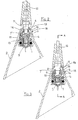
- Figure 7 shows the longitudinal section of the joint with its lower threaded end aligned, screwed and fastened to the second threaded hole of the support base and the inclined orientation of the antenna towards the roof of the vehicles.
-
- With reference to the Figures, it can be noticed that the fastening base 1 of a
support 2 for a rod antenna comprises acircular seat 3 withside saddles 4 wherein acylindrical drum 5 which can rotate inside the same saddles is housed and a diametralcentral space 6 is obtained with anarrowed access hole 7 forming an upper counterboring 7' with aconical raiser 8. On thecircular seat 3 two threadedholes base 11 of therod 12 comprises a lower threadedend 13 and an upper tang hold 14 on which asnap ring 15 withlongitudinal notch 16 and lowerconical raiser 17 is placed. During the first installation, the lower threadedend 13 of therod 12 passes through the diametralcentral seat 6 of thecylindrical drum 5 and it is then coupled and screwed into the threadedhole 9 obtained in the base 1 and oriented in the direction of the proper reception of the antenna together with thesupport 2. - With the screwing, the
snap ring 15 is pushed from thebase 11 against theconical raiser 8 and it is forced to narrow in order to pass through thenarrowed access hole 7, to open again under the counterboring 7' of the diametralcentral space 6 of thecylindrical drum 5 and stay inside the same space without return. The narrowing of thering 15 is allowed by the presence of thelongitudinal notch 16 and by the lowerconical raiser 17 together with inherent elasticity of the material used for its manufacturing. In this condition thesnap ring 15 takes a narrowed position which is sufficient to allow the sliding of the tang hold 14 and it constitutes a counterboring against which thethreading 13, even though unscrewed, collides without any possibility to pass through in such a way that therod 12 cannot be withdrawn from the base 1. - When the antenna must be bended towards the roof of the vehicles to submit them to the subsequent in-line assembly steps at manufacturers' plants, to the transportation by two tier car carriers or trains, to the automatic washing with roller brushes, the threaded
end 13 can be unscrewed from the threadedhole 9 of the base 1 until the same end is completely withdrawn inside thespace 6 which is not occupied by thesnap ring 15; in this position therod 12 can be then rotated along thecircular seat 3, due to the fact that even thecylindrical drum 5 rotates supported by thecircular side saddles 4. This rotation can be carried out also because thesupport 2 comprises alateral slit 18 aligned to theaccess hole 7 of thecylindrical drum 5 allowing the passage of thebase 11 of the rod. Once the alignment of therod 12 with the second threadedhole 10 is reached, the lower threadedend 13 can be screwed again and the rod takes the second fixed inclined position towards the roof of the vehicles keeping it steady during said manufacturing, transportation and washing steps. - The
lateral slit 18 of thesupport 2, for the passage and the inclined positioning of thebase 11 of the antenna can be carried out withopposite side notches 19 whose distance among them is lower than the diameter of the same base. According to the elasticity of the plastic material with which thesupport 2 is made of, during the rotation and the passage of thebase 11, thenotches 19 are forced to elastically wide in order to narrow immediately afterwards thus imposing to the antenna the exact alignment with the threadedhole 10 to give it a further stability.
Claims (10)
- A joint for a roof antenna with anti-withdrawal device of the rod characterized by the fact that it is constituted by a snap ring (15) that engages against a counterboring (7) obtained in the diametral central space (6) of a cylindrical drum (5) placed in a circular seat (3) on the fastening base (1) of the same joint, constitutes itself a counterboring against which the threaded lower end (13) of the base (11) of the rod (12) of an antenna engages without possibility of withdrawal and passes through the same diametral central seat (6); this threaded end (13) which is engaged without possibility of withdrawal on the fastening base (1) and it can be screwed into two different threaded holes (9) and (10) which are obtained on the surface of the same circular seat (3); said hole (9) is directed for the constrained reception orientation of the antenna and said hole (10) is directed for the constrained orientation of the rod which is inclined towards the roof of the vehicle on which the antenna is installed.
- The joint for roof antenna with anti-withdrawal device of the rod according to claim 1, characterized by the fact that said snap ring (15) comprises a longitudinal notch (16) and a lower conical raiser (17) and it is placed around a tang hold (14) made over said lower threaded end (13) of the base (11) of the rod (12).
- The joint for roof antenna with anti-withdrawal device of the rod according to claims 1 and 2, characterized by the fact that the snap ring (15) engages against the counterboring (7') which is obtained in the diametral central space (6) of said cylindrical drum (5) through the first screwing of said lower threaded end (13) into the first threaded hole (9) which is directed for the constrained reception orientation of the antenna; in said screwing, the snap ring (15) is pushed from the base (11) against the conical raiser (8) of said diametral central space (6) and it is forced to tighten until it passes through the narrowed access hole (7) to open again under the counterboring (7') with stay inside the space (6) without return.
- The joint for roof antenna with anti-withdrawal device of the rod according to claims 1, 2 and 3, characterized by the fact that the narrowing/widening of the ring (15) is function of the longitudinal notch (16), of the lower conical raiser (17) and of the inherent elasticity of the material used for its manufacturing.
- The joint for roof antenna with anti-withdrawal device of the rod according to claims from 1 to 4, characterized by the fact that the snap ring (15) engaged with the counterboring (7') takes a position that allows the sliding of the tang hold (14) and constitutes a counterboring against which the thread (13) engages without possibility of withdrawal and extraction of the rod (12) from the base (1) even though it is unscrewed from the threaded hole (9).
- The joint for roof antenna with anti-withdrawal device of the rod according to claims 1 to 5, characterized by the fact that the threaded end (13) which is screwed to the threaded hole (9) of the base (1) can be unscrewed from the same hole and it is completely retractable inside the diametral central space (6) which is not occupied by the snap ring (15).
- The joint for roof antenna with anti-withdrawal device of the rod according to claims from 1 to 6, characterized by the fact that when the threaded end (13) is unscrewed from the threaded hole (9) of the base (1) and completely retracted inside the diametral central space (6), the rod (12) rotates along the circular seat (3) and the cylindrical drum (5) rotates together with it on side circular saddles (4).
- A joint for roof antenna with anti-withdrawal device of the rod according to claims from 1 to 7, characterized by the fact that, with the rotation along the circular seat (3), the lower threaded end (13) can be aligned and steadily screwed to the second threaded hole (10) and the rod takes the second fixed inclined position towards the roofs of the vehicles.
- The joint for roof antenna with anti-withdrawal device of the rod according to claims from 1 to 7, characterized by the fact that, with the rotation in one direction or in the opposite one along the circular seat (3) the lower threaded end (13) can be aligned and steadily screwed both to the first threaded hole (9) and to the second threaded hole (10) obtained on the surface of the same circular seat (3) and the rod takes the correspondent first fixed orientation position for the reception of the antenna, or the correspondent second fixed inclined position towards the roof of the vehicles.
- The joint for roof antenna with anti-withdrawal device of the rod according to claims from 1 to 7, characterized by the fact that the support (2) comprises a side slit (18) for the passage and the inclined positioning of the base (11) equipped with opposite side notches (19) whose distance among them is lower than the diameter of the same base; said support (2) and said relevant notches (19) are made of elastic plastic material.
Applications Claiming Priority (2)
| Application Number | Priority Date | Filing Date | Title |
|---|---|---|---|
| ITRE20020016U | 2002-06-21 | ||
| IT2002RE000016U ITRE20020016U1 (en) | 2002-06-21 | 2002-06-21 | JOINT FOR ROOF ANTENNA, WITH STEM ANTI-TRACTION DEVICE |
Publications (3)
| Publication Number | Publication Date |
|---|---|
| EP1375256A2 true EP1375256A2 (en) | 2004-01-02 |
| EP1375256A3 EP1375256A3 (en) | 2004-11-10 |
| EP1375256B1 EP1375256B1 (en) | 2008-08-13 |
Family
ID=29717163
Family Applications (1)
| Application Number | Title | Priority Date | Filing Date |
|---|---|---|---|
| EP02028907A Expired - Lifetime EP1375256B1 (en) | 2002-06-21 | 2002-12-23 | Joint for roof antenna with anti-withdrawal device of the rod |
Country Status (4)
| Country | Link |
|---|---|
| EP (1) | EP1375256B1 (en) |
| AT (1) | ATE404405T1 (en) |
| DE (1) | DE60228216D1 (en) |
| IT (1) | ITRE20020016U1 (en) |
Cited By (3)
| Publication number | Priority date | Publication date | Assignee | Title |
|---|---|---|---|---|
| WO2007048501A1 (en) * | 2005-10-26 | 2007-05-03 | A. Raymond Et Cie | Antenna arrangement |
| WO2009059570A1 (en) * | 2007-11-09 | 2009-05-14 | Antennentechnik Blankenburg Ag | Rod antenna having pivotal antenna rod |
| US20150340760A1 (en) * | 2007-06-29 | 2015-11-26 | Barry Booth | E-Z fit antenna base |
Families Citing this family (2)
| Publication number | Priority date | Publication date | Assignee | Title |
|---|---|---|---|---|
| JP4605286B2 (en) * | 2008-11-28 | 2011-01-05 | ミツミ電機株式会社 | Antenna device |
| JP5463950B2 (en) * | 2010-02-23 | 2014-04-09 | ミツミ電機株式会社 | Antenna device |
Family Cites Families (3)
| Publication number | Priority date | Publication date | Assignee | Title |
|---|---|---|---|---|
| DE4005029C2 (en) * | 1990-02-19 | 1994-08-11 | Hirschmann Richard Gmbh Co | Vehicle antenna |
| IT1267852B1 (en) * | 1994-09-07 | 1997-02-18 | Massimo Calearo | MOTOR VEHICLE ANTENNA. |
| ITVI980153A1 (en) * | 1998-08-11 | 2000-02-11 | Massimo Calearo | ANTITHEFT ANTENNA |
-
2002
- 2002-06-21 IT IT2002RE000016U patent/ITRE20020016U1/en unknown
- 2002-12-23 DE DE60228216T patent/DE60228216D1/en not_active Expired - Lifetime
- 2002-12-23 EP EP02028907A patent/EP1375256B1/en not_active Expired - Lifetime
- 2002-12-23 AT AT02028907T patent/ATE404405T1/en not_active IP Right Cessation
Non-Patent Citations (1)
| Title |
|---|
| None |
Cited By (4)
| Publication number | Priority date | Publication date | Assignee | Title |
|---|---|---|---|---|
| WO2007048501A1 (en) * | 2005-10-26 | 2007-05-03 | A. Raymond Et Cie | Antenna arrangement |
| US20150340760A1 (en) * | 2007-06-29 | 2015-11-26 | Barry Booth | E-Z fit antenna base |
| US9705176B2 (en) * | 2007-06-29 | 2017-07-11 | Barry Booth | E-Z fit antenna base |
| WO2009059570A1 (en) * | 2007-11-09 | 2009-05-14 | Antennentechnik Blankenburg Ag | Rod antenna having pivotal antenna rod |
Also Published As
| Publication number | Publication date |
|---|---|
| EP1375256A3 (en) | 2004-11-10 |
| DE60228216D1 (en) | 2008-09-25 |
| ATE404405T1 (en) | 2008-08-15 |
| ITRE20020016U1 (en) | 2003-12-22 |
| EP1375256B1 (en) | 2008-08-13 |
Similar Documents
| Publication | Publication Date | Title |
|---|---|---|
| US7121573B2 (en) | Vehicle accessory mounting system | |
| US6409029B1 (en) | Trimmer rack | |
| US5460306A (en) | Lockable fishing rod holder | |
| US5996736A (en) | Ladder locking device | |
| US9702175B2 (en) | Hinge and locking device | |
| EP1375256B1 (en) | Joint for roof antenna with anti-withdrawal device of the rod | |
| US5273384A (en) | Thread protecting device | |
| DE2941711A1 (en) | COUPE COVER FOR MOTOR VEHICLES | |
| US20090230656A1 (en) | Hitch Securement System | |
| EP1980444A2 (en) | Fixing device for additional mats in a motor vehicle | |
| US20030034206A1 (en) | Universal ladder lock and method | |
| US5899101A (en) | Security device for a chassis or frame | |
| US6715653B2 (en) | Adjustable rack and clamping apparatus for removably retaining surfboards or the like on a vehicle | |
| US6662751B1 (en) | Tie-out system | |
| KR880000280B1 (en) | Seat belt retractor and its assembly method | |
| KR950704131A (en) | Locking Device (DISABLING DEVICE) | |
| US5987938A (en) | Trailer kingpin locking apparatus | |
| WO2017060004A1 (en) | Mounting for a u-lock | |
| DE202019101860U1 (en) | Lockable roof accessory mounting interface | |
| US5347836A (en) | Configuration of automobile steering wheel locking devices | |
| EP4086205B1 (en) | Format part, attachment for a format part and method of assembling a format part | |
| DE19857722B4 (en) | Device with electronic data carrier for identification and labeling of compressed gas cylinders and corresponding compressed gas cylinder | |
| US6536726B1 (en) | Mounting device for boat tower | |
| EP2213558A1 (en) | Helmet fixing device for bicycles | |
| CN116997487A (en) | Vehicle roof load bar mounting system |
Legal Events
| Date | Code | Title | Description |
|---|---|---|---|
| PUAI | Public reference made under article 153(3) epc to a published international application that has entered the european phase |
Free format text: ORIGINAL CODE: 0009012 |
|
| AK | Designated contracting states |
Kind code of ref document: A2 Designated state(s): AT BE BG CH CY CZ DE DK EE ES FI FR GB GR IE IT LI LU MC NL PT SE SI SK TR |
|
| AX | Request for extension of the european patent |
Extension state: AL LT LV MK RO |
|
| PUAL | Search report despatched |
Free format text: ORIGINAL CODE: 0009013 |
|
| AK | Designated contracting states |
Kind code of ref document: A3 Designated state(s): AT BE BG CH CY CZ DE DK EE ES FI FR GB GR IE IT LI LU MC NL PT SE SI SK TR |
|
| AX | Request for extension of the european patent |
Extension state: AL LT LV MK RO |
|
| AKX | Designation fees paid |
Designated state(s): AT BE BG CH CY CZ DE DK EE ES FI FR GB GR IE IT LI LU MC NL PT SE SI SK TR |
|
| 17P | Request for examination filed |
Effective date: 20050601 |
|
| GRAP | Despatch of communication of intention to grant a patent |
Free format text: ORIGINAL CODE: EPIDOSNIGR1 |
|
| GRAS | Grant fee paid |
Free format text: ORIGINAL CODE: EPIDOSNIGR3 |
|
| GRAA | (expected) grant |
Free format text: ORIGINAL CODE: 0009210 |
|
| AK | Designated contracting states |
Kind code of ref document: B1 Designated state(s): AT BE BG CH CY CZ DE DK EE ES FI FR GB GR IE IT LI LU MC NL PT SE SI SK TR |
|
| REG | Reference to a national code |
Ref country code: GB Ref legal event code: FG4D |
|
| REG | Reference to a national code |
Ref country code: CH Ref legal event code: EP |
|
| REG | Reference to a national code |
Ref country code: IE Ref legal event code: FG4D |
|
| REF | Corresponds to: |
Ref document number: 60228216 Country of ref document: DE Date of ref document: 20080925 Kind code of ref document: P |
|
| PG25 | Lapsed in a contracting state [announced via postgrant information from national office to epo] |
Ref country code: NL Free format text: LAPSE BECAUSE OF FAILURE TO SUBMIT A TRANSLATION OF THE DESCRIPTION OR TO PAY THE FEE WITHIN THE PRESCRIBED TIME-LIMIT Effective date: 20080813 Ref country code: ES Free format text: LAPSE BECAUSE OF FAILURE TO SUBMIT A TRANSLATION OF THE DESCRIPTION OR TO PAY THE FEE WITHIN THE PRESCRIBED TIME-LIMIT Effective date: 20081124 |
|
| PG25 | Lapsed in a contracting state [announced via postgrant information from national office to epo] |
Ref country code: SI Free format text: LAPSE BECAUSE OF FAILURE TO SUBMIT A TRANSLATION OF THE DESCRIPTION OR TO PAY THE FEE WITHIN THE PRESCRIBED TIME-LIMIT Effective date: 20080813 Ref country code: AT Free format text: LAPSE BECAUSE OF FAILURE TO SUBMIT A TRANSLATION OF THE DESCRIPTION OR TO PAY THE FEE WITHIN THE PRESCRIBED TIME-LIMIT Effective date: 20080813 Ref country code: FI Free format text: LAPSE BECAUSE OF FAILURE TO SUBMIT A TRANSLATION OF THE DESCRIPTION OR TO PAY THE FEE WITHIN THE PRESCRIBED TIME-LIMIT Effective date: 20080813 |
|
| PG25 | Lapsed in a contracting state [announced via postgrant information from national office to epo] |
Ref country code: BE Free format text: LAPSE BECAUSE OF FAILURE TO SUBMIT A TRANSLATION OF THE DESCRIPTION OR TO PAY THE FEE WITHIN THE PRESCRIBED TIME-LIMIT Effective date: 20080813 |
|
| PG25 | Lapsed in a contracting state [announced via postgrant information from national office to epo] |
Ref country code: DK Free format text: LAPSE BECAUSE OF FAILURE TO SUBMIT A TRANSLATION OF THE DESCRIPTION OR TO PAY THE FEE WITHIN THE PRESCRIBED TIME-LIMIT Effective date: 20080813 Ref country code: BG Free format text: LAPSE BECAUSE OF FAILURE TO SUBMIT A TRANSLATION OF THE DESCRIPTION OR TO PAY THE FEE WITHIN THE PRESCRIBED TIME-LIMIT Effective date: 20081113 |
|
| PG25 | Lapsed in a contracting state [announced via postgrant information from national office to epo] |
Ref country code: SK Free format text: LAPSE BECAUSE OF FAILURE TO SUBMIT A TRANSLATION OF THE DESCRIPTION OR TO PAY THE FEE WITHIN THE PRESCRIBED TIME-LIMIT Effective date: 20080813 Ref country code: PT Free format text: LAPSE BECAUSE OF FAILURE TO SUBMIT A TRANSLATION OF THE DESCRIPTION OR TO PAY THE FEE WITHIN THE PRESCRIBED TIME-LIMIT Effective date: 20090113 Ref country code: CZ Free format text: LAPSE BECAUSE OF FAILURE TO SUBMIT A TRANSLATION OF THE DESCRIPTION OR TO PAY THE FEE WITHIN THE PRESCRIBED TIME-LIMIT Effective date: 20080813 |
|
| PLBE | No opposition filed within time limit |
Free format text: ORIGINAL CODE: 0009261 |
|
| STAA | Information on the status of an ep patent application or granted ep patent |
Free format text: STATUS: NO OPPOSITION FILED WITHIN TIME LIMIT |
|
| 26N | No opposition filed |
Effective date: 20090514 |
|
| PG25 | Lapsed in a contracting state [announced via postgrant information from national office to epo] |
Ref country code: EE Free format text: LAPSE BECAUSE OF FAILURE TO SUBMIT A TRANSLATION OF THE DESCRIPTION OR TO PAY THE FEE WITHIN THE PRESCRIBED TIME-LIMIT Effective date: 20080813 Ref country code: MC Free format text: LAPSE BECAUSE OF NON-PAYMENT OF DUE FEES Effective date: 20081231 |
|
| REG | Reference to a national code |
Ref country code: CH Ref legal event code: PL |
|
| GBPC | Gb: european patent ceased through non-payment of renewal fee |
Effective date: 20081223 |
|
| PG25 | Lapsed in a contracting state [announced via postgrant information from national office to epo] |
Ref country code: IT Free format text: LAPSE BECAUSE OF FAILURE TO SUBMIT A TRANSLATION OF THE DESCRIPTION OR TO PAY THE FEE WITHIN THE PRESCRIBED TIME-LIMIT Effective date: 20080813 |
|
| REG | Reference to a national code |
Ref country code: FR Ref legal event code: ST Effective date: 20090831 |
|
| PG25 | Lapsed in a contracting state [announced via postgrant information from national office to epo] |
Ref country code: CH Free format text: LAPSE BECAUSE OF NON-PAYMENT OF DUE FEES Effective date: 20081231 Ref country code: LI Free format text: LAPSE BECAUSE OF NON-PAYMENT OF DUE FEES Effective date: 20081231 Ref country code: IE Free format text: LAPSE BECAUSE OF NON-PAYMENT OF DUE FEES Effective date: 20081223 |
|
| PG25 | Lapsed in a contracting state [announced via postgrant information from national office to epo] |
Ref country code: GB Free format text: LAPSE BECAUSE OF NON-PAYMENT OF DUE FEES Effective date: 20081223 |
|
| PG25 | Lapsed in a contracting state [announced via postgrant information from national office to epo] |
Ref country code: SE Free format text: LAPSE BECAUSE OF FAILURE TO SUBMIT A TRANSLATION OF THE DESCRIPTION OR TO PAY THE FEE WITHIN THE PRESCRIBED TIME-LIMIT Effective date: 20081113 |
|
| PG25 | Lapsed in a contracting state [announced via postgrant information from national office to epo] |
Ref country code: FR Free format text: LAPSE BECAUSE OF NON-PAYMENT OF DUE FEES Effective date: 20081231 |
|
| PG25 | Lapsed in a contracting state [announced via postgrant information from national office to epo] |
Ref country code: LU Free format text: LAPSE BECAUSE OF NON-PAYMENT OF DUE FEES Effective date: 20081223 Ref country code: CY Free format text: LAPSE BECAUSE OF FAILURE TO SUBMIT A TRANSLATION OF THE DESCRIPTION OR TO PAY THE FEE WITHIN THE PRESCRIBED TIME-LIMIT Effective date: 20080813 |
|
| PG25 | Lapsed in a contracting state [announced via postgrant information from national office to epo] |
Ref country code: TR Free format text: LAPSE BECAUSE OF FAILURE TO SUBMIT A TRANSLATION OF THE DESCRIPTION OR TO PAY THE FEE WITHIN THE PRESCRIBED TIME-LIMIT Effective date: 20080813 |
|
| PG25 | Lapsed in a contracting state [announced via postgrant information from national office to epo] |
Ref country code: GR Free format text: LAPSE BECAUSE OF FAILURE TO SUBMIT A TRANSLATION OF THE DESCRIPTION OR TO PAY THE FEE WITHIN THE PRESCRIBED TIME-LIMIT Effective date: 20081114 |
|
| REG | Reference to a national code |
Ref country code: DE Ref legal event code: R082 Ref document number: 60228216 Country of ref document: DE Representative=s name: KLINGSEISEN, RINGS & PARTNER PATENTANWAELTE, DE |
|
| PGFP | Annual fee paid to national office [announced via postgrant information from national office to epo] |
Ref country code: DE Payment date: 20210224 Year of fee payment: 19 |
|
| REG | Reference to a national code |
Ref country code: DE Ref legal event code: R119 Ref document number: 60228216 Country of ref document: DE |
|
| PG25 | Lapsed in a contracting state [announced via postgrant information from national office to epo] |
Ref country code: DE Free format text: LAPSE BECAUSE OF NON-PAYMENT OF DUE FEES Effective date: 20220701 |