EP1375245A2 - Vehicle headrest apparatus - Google Patents
Vehicle headrest apparatus Download PDFInfo
- Publication number
- EP1375245A2 EP1375245A2 EP03014168A EP03014168A EP1375245A2 EP 1375245 A2 EP1375245 A2 EP 1375245A2 EP 03014168 A EP03014168 A EP 03014168A EP 03014168 A EP03014168 A EP 03014168A EP 1375245 A2 EP1375245 A2 EP 1375245A2
- Authority
- EP
- European Patent Office
- Prior art keywords
- support portion
- members
- headrest
- recited
- head
- Prior art date
- Legal status (The legal status is an assumption and is not a legal conclusion. Google has not performed a legal analysis and makes no representation as to the accuracy of the status listed.)
- Granted
Links
- 230000000452 restraining effect Effects 0.000 claims abstract description 69
- 230000007246 mechanism Effects 0.000 claims description 54
- 239000000463 material Substances 0.000 claims description 21
- 238000003825 pressing Methods 0.000 claims description 12
- 230000004044 response Effects 0.000 claims description 8
- 238000005452 bending Methods 0.000 claims description 6
- 238000006073 displacement reaction Methods 0.000 claims description 6
- 230000008261 resistance mechanism Effects 0.000 claims description 5
- 230000002093 peripheral effect Effects 0.000 claims description 4
- 230000001105 regulatory effect Effects 0.000 claims description 3
- 230000005489 elastic deformation Effects 0.000 claims 1
- 239000012858 resilient material Substances 0.000 abstract description 2
- 239000011162 core material Substances 0.000 description 73
- 239000010410 layer Substances 0.000 description 35
- 238000004804 winding Methods 0.000 description 33
- 239000012792 core layer Substances 0.000 description 21
- 230000013011 mating Effects 0.000 description 20
- 230000006870 function Effects 0.000 description 12
- 210000000078 claw Anatomy 0.000 description 10
- 238000001514 detection method Methods 0.000 description 8
- 239000004417 polycarbonate Substances 0.000 description 7
- 229920000515 polycarbonate Polymers 0.000 description 7
- 239000004744 fabric Substances 0.000 description 6
- 230000002829 reductive effect Effects 0.000 description 6
- 230000036961 partial effect Effects 0.000 description 4
- 210000005069 ears Anatomy 0.000 description 3
- 238000000034 method Methods 0.000 description 3
- 230000008569 process Effects 0.000 description 3
- 230000035939 shock Effects 0.000 description 3
- 230000001360 synchronised effect Effects 0.000 description 3
- PPBRXRYQALVLMV-UHFFFAOYSA-N Styrene Chemical compound C=CC1=CC=CC=C1 PPBRXRYQALVLMV-UHFFFAOYSA-N 0.000 description 2
- 230000009471 action Effects 0.000 description 2
- 230000000052 comparative effect Effects 0.000 description 2
- 238000010586 diagram Methods 0.000 description 2
- 239000006261 foam material Substances 0.000 description 2
- 230000000670 limiting effect Effects 0.000 description 2
- 239000002184 metal Substances 0.000 description 2
- 230000004048 modification Effects 0.000 description 2
- 238000012986 modification Methods 0.000 description 2
- 241000638935 Senecio crassissimus Species 0.000 description 1
- 229910000639 Spring steel Inorganic materials 0.000 description 1
- 229920006362 Teflon® Polymers 0.000 description 1
- 230000001276 controlling effect Effects 0.000 description 1
- 230000007423 decrease Effects 0.000 description 1
- 230000003247 decreasing effect Effects 0.000 description 1
- 230000000994 depressogenic effect Effects 0.000 description 1
- 239000013013 elastic material Substances 0.000 description 1
- 229920006351 engineering plastic Polymers 0.000 description 1
- 239000002360 explosive Substances 0.000 description 1
- 239000006260 foam Substances 0.000 description 1
- 230000001681 protective effect Effects 0.000 description 1
- 230000003014 reinforcing effect Effects 0.000 description 1
- 230000000630 rising effect Effects 0.000 description 1
- 238000009958 sewing Methods 0.000 description 1
- 229920003002 synthetic resin Polymers 0.000 description 1
- 239000000057 synthetic resin Substances 0.000 description 1
Images


Classifications
-
- B—PERFORMING OPERATIONS; TRANSPORTING
- B60—VEHICLES IN GENERAL
- B60N—SEATS SPECIALLY ADAPTED FOR VEHICLES; VEHICLE PASSENGER ACCOMMODATION NOT OTHERWISE PROVIDED FOR
- B60N2/00—Seats specially adapted for vehicles; Arrangement or mounting of seats in vehicles
- B60N2/80—Head-rests
- B60N2/806—Head-rests movable or adjustable
- B60N2/865—Head-rests movable or adjustable providing a fore-and-aft movement with respect to the occupant's head
-
- B—PERFORMING OPERATIONS; TRANSPORTING
- B60—VEHICLES IN GENERAL
- B60N—SEATS SPECIALLY ADAPTED FOR VEHICLES; VEHICLE PASSENGER ACCOMMODATION NOT OTHERWISE PROVIDED FOR
- B60N2/00—Seats specially adapted for vehicles; Arrangement or mounting of seats in vehicles
- B60N2/80—Head-rests
- B60N2/888—Head-rests with arrangements for protecting against abnormal g-forces, e.g. by displacement of the head-rest
-
- B—PERFORMING OPERATIONS; TRANSPORTING
- B60—VEHICLES IN GENERAL
- B60N—SEATS SPECIALLY ADAPTED FOR VEHICLES; VEHICLE PASSENGER ACCOMMODATION NOT OTHERWISE PROVIDED FOR
- B60N2/00—Seats specially adapted for vehicles; Arrangement or mounting of seats in vehicles
- B60N2/02—Seats specially adapted for vehicles; Arrangement or mounting of seats in vehicles the seat or part thereof being movable, e.g. adjustable
- B60N2002/0204—Seats specially adapted for vehicles; Arrangement or mounting of seats in vehicles the seat or part thereof being movable, e.g. adjustable characterised by the seat or seat part turning about or moving along a non-standard, particular axis, i.e. an axis different from the axis characterising the conventional movement
- B60N2002/022—Seats specially adapted for vehicles; Arrangement or mounting of seats in vehicles the seat or part thereof being movable, e.g. adjustable characterised by the seat or seat part turning about or moving along a non-standard, particular axis, i.e. an axis different from the axis characterising the conventional movement the seat or seat part turning about or moving along a vertical axis
Definitions
- the present invention generally relates to a vehicle headrest apparatus that is used on a vehicle seat and supports the head of a seated passenger. More specifically, the present invention relates to a vehicle headrest apparatus that is configured to reliably restrain a passenger's head and suppress the rearward movement of a passenger's head when a rear-end collision occurs by actuating a headrest unit itself.
- Japanese Laid-Open Patent Publication No. 7-291005 in which the seatback is designed to protect the head of a seated passenger in the event of a rear-end collision.
- this Japanese publication discloses a seatback that bears the dynamic load acting on a seated passenger due to the inertia force when a vehicle is subjected to a rear-end collision. The movement of a member that is displaced as a result is transmitted to a headrest support arm and the headrest unit moves toward the front of the vehicle. As a result, a large rearward movement of the seated passenger's head can be prevented.
- the present invention seeks to provide a vehicle headrest apparatus that quickly and reliably restrains a seated passenger's head during a rear-end collision without utilizing the inertia force of the passenger's body by detecting the rear-end collision and pushing the headrest unit alone outward in the forward direction of the vehicle.
- one object of the present invention is to provide a vehicle headrest apparatus that can restrain a passenger's head reliably when a rear-end collision occurs by actuating headrest unit itself.
- a vehicle headrest apparatus basically comprises a headrest portion, a head restraining member and a tensioning device.
- the headrest portion with a mounting member is configured to be mounted to an upper end part of a seatback.
- the head restraining member includes a vertical support portion arranged to face towards a passenger's head and a horizontal support portion arranged substantially perpendicular to the vertical support portion.
- the tensioning device isoperatively coupled to the head restraining member to apply tension to at least part of the vertical support portion when a rear-end collision occurs.
- Figure 1 is a front perspective view of a headrest unit (portions being transparent for purposes of illustration) in accordance with the first embodiment of the present invention when in the initial state;
- Figure 2 is an overall perspective view of a seat installed with the headrest unit of the first embodiment of the present invention with the cushion pads removed for purposes of illustration;
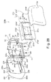
- Figure 3 is an enlarged perspective view of the headrest unit of the first embodiment of the present invention with portions broken away to show some of the main components;
- Figure 4 is a front perspective view of the headrest unit of the first embodiment of the present invention in a completely deployed state with the cushion pads removed;
- Figure 5 is a simplified top plan view of the headrest unit of the first embodiment of the present invention while deployment is in progress;
- Figure 6 is a simplified top plan view of the headrest unit of the first embodiment of the present invention after deployment has been completed;
- Figure 7 is a cross-sectional view of the locking device showing the initial holding state of the lock device of the first embodiment of the present invention
- Figure 8 is a cross-sectional view of the locking device showing the state after the lock device of the first embodiment of the present invention has been released;
- Figure 9 is an enlarged perspective view of the winding element for the lock device of the first embodiment of the present invention.
- Figure 10 is a schematic view illustrating the actuation system of the controller of the first embodiment of the present invention.
- Figure 11 is a rear perspective view of the fastening or resistance mechanism of the first embodiment of the present invention.
- Figure 12 is a simplified schematic cross-sectional view of the main components of the fastening or resistance mechanism in the first embodiment of the present invention.
- Figure 13 is a simplified top plan view showing the operation of the fastening or resistance mechanism of the first embodiment of the present invention in the locked state;
- Figure 14 is a flowchart explaining the control of the lock device of the first embodiment of the present invention.
- Figure 15 is a graph for describing the region in which the lock device of the first embodiment of the present invention is released based on the relative distance and relative velocity;
- Figure 16 is a simplified schematic side elevational view of the headrest apparatus of the first embodiment of the present invention during normal driving;
- Figure 17 is a simplified schematic side elevational view of the headrest apparatus of the first embodiment of the present invention when a rear-end collision occurs;
- Figure 18 is a comparative characteristic diagram of the downward moment exerted by the headrest apparatus on the passenger's neck in the first embodiment of the present invention.
- Figure 19 is a front perspective view of a headrest unit in accordance with a second embodiment of the present invention in a completely deployed state with the cushion pads removed for purposes of illustration;
- Figure 20 is a simplified rear perspective view of the headrest unit of the second embodiment of the present invention in the completely deployed state with the cushion pads removed for purposes of illustration;
- Figure 21 is a simplified top plan view of the headrest unit of the second embodiment of the present invention in the completely deployed state after the load of the passenger's head has been delivered and with the cushion pads removed for purposes of illustration;
- Figure 22 is an enlarged cross-sectional perspective view of a headrest unit in accordance with a third embodiment of the present invention with portions broken away to show some of the main components;
- Figure 23 is a simplified rear perspective view of the headrest unit of the third embodiment of the present invention when in the completely deployed state with the cushion pads removed for purposes of illustration;
- Figure 24 is a simplified top plan view of the headrest unit of the third embodiment of the present invention in the completely deployed state after the load of the passenger's head has been delivered and with the cushion pads removed for purposes of illustration;
- Figure 25 is a simplified rear perspective view of a headrest unit in accordance with a fourth embodiment of the present invention when in the completely deployed state with the cushion pads removed for purposes of illustration;
- Figure 26 is a front perspective view of a headrest unit (portions being transparent for purposes of illustration) in accordance with a fifth embodiment of the present invention when in the initial state;
- Figure 27 is a simplified schematic side elevational view of the mounted state of the headrest unit of the fifth embodiment of the present invention.
- Figure 28 is an exploded front perspective view of the headrest unit of the fifth embodiment of the present invention.
- Figure 29 is an exploded front perspective view of the headrest unit (portions being transparent for purposes of illustration) of the fifth embodiment of the present invention during assembly;
- Figure 30 is a simplified, exploded rear perspective view of the headrest unit (portions being transparent for purposes of illustration) of the fifth embodiment of the present invention during assembly;
- Figure 31 is a simplified rear perspective view of the headrest unit (portions being transparent for purposes of illustration) of the fifth embodiment of the present invention in its assembled state;
- Figure 32 is an enlarged cross-sectional view taken along the line 32-32 in Figure 28;
- Figure 33 is a simplified rear perspective view of the mounted state of the head restraining member of the fifth embodiment of the present invention on the left and right headrest members before deployment;
- Figure 34 is a simplified rear perspective view of the mounted state of the head restraining member of the fifth embodiment of the present invention on the left and right headrest members after deployment;
- Figure 35 is a front perspective view of the headrest unit (portions being transparent for purposes of illustration) of the fifth embodiment of the present invention in the deployed state;
- Figure 36 is a sequential schematic view illustrating the operation of the lock device or mechanism of the fifth embodiment of the present invention in the order of steps (a) to (d);
- Figure 37 is a simplified top plan view of the headrest unit (portions being transparent for purposes of illustration) of the fifth embodiment of the present invention during deployment immediately after a rear-end collision;
- Figure 38 is a simplified schematic side elevational view of the headrest unit of the fifth embodiment of the present invention showing the completely deployed state after a rear-end collision;
- Figure 39 is a simplified top plan view of the headrest unit (portions being transparent for purposes of illustration) of the first embodiment of the present invention in the completely deployed state after a rear-end collision;
- Figure 40 is a simplified partial rear perspective view of a head restraining member in accordance with a sixth embodiment of the present invention.
- Figure 41 is a simplified partial rear perspective view of a head restraining member in accordance with a seventh embodiment of the present invention.
- Figure 42 is a simplified rear perspective view of a head restraining member in accordance with an eighth embodiment of the present invention.
- Figure 43 is a simplified top plan view of a headrest unit (portions being transparent for purposes of illustration) in accordance with a ninth embodiment of the present invention.
- Figure 44 is a simplified rear perspective view of left and right headrest members in accordance with a tenth embodiment of the present invention.
- Figure 45 is a front perspective view of the headrest unit (portions being transparent for purposes of illustration) of an eleventh embodiment of the present invention in an undeployed state;
- Figure 46 is a simplified exploded rear perspective view of the headrest unit of the eleventh embodiment of the present invention in the completely deployed state with the selected components and parts removed for purposes of illustration;
- Figure 47 is a simplified exploded rear perspective view of the cushion pad and the head restraining member in the extended state in accordance with the eleventh embodiment of the present invention on the left and right headrest members after deployment;
- Figure 48 is a simplified transverse cross-sectional view of the headrest unit of the eleventh embodiment of the present invention in the completely deployed state, but prior to the load of the passenger's head being pressed against the cushion pad;
- Figure 49 is a simplified transverse cross-sectional view of the headrest unit of the eleventh embodiment of the present invention in the completely deployed state after the load of the passenger's head has been delivered against the cushion pads;
- Figure 50 is a simplified rear perspective view of the cushion pad and selected parts of the head restraining member in the extended state in accordance with a twelfth embodiment of the present invention
- Figure 51 is an enlarged perspective view of one of the vertical frame members of the tensioning member for the head restraining member in accordance with the twelfth embodiment of the present invention.
- Figure 52 is a partial enlarged elevational view of a portion of the retaining element of the cushion pad for the head restraining member in an unstressed state in accordance with the twelfth embodiment of the present invention.
- Figure 53 is a partial enlarged elevational view of the portion of the retaining element illustrated in Figure 52 in a stressed state in accordance with the twelfth embodiment of the present invention.
- the present invention is directed to a vehicle headrest apparatus that is configured to reliably restrain a passenger's head and suppress the rearward movement of a passenger's head when a rear-end collision occurs by actuating headrest unit itself.
- the vehicle headrest apparatus basically includes a head restraining member having vertical and horizontal sheet support portions with a vertical tension applying member that applies tension to the vertical sheet support portion and a horizontal tension applying member that applies tension to the horizontal sheet support portion when a rear-end collision occurs.
- the vertical sheet support portion (which faces the passenger's head) can stop a rearward movement of a passenger's head caused by an inertia force and restrain the passenger's head without delay.
- the head restraining member is provided with a horizontal sheet portion in addition to the vertical sheet support portion, the passenger's head can be restrained by the horizontal sheet support portion as well. Consequently, the head restraining capacity of the head restraining member is increased further, rearward movement of the passenger's head can be suppressed effectively, and the head of a seated passenger can be protected.
- the vehicle headrest apparatus uses a swinging force that swings the left and right headrest members forward and upward from an initial storage position.
- the left and right headrest members are unlocked based on the detection of the rear-end collision so as to swing forward and upward to push the head restraining member toward the front of the vehicle, enabling the passenger's head to be restrained against rearward movement.
- this arrangement allows the head restraining member alone to be pushed out quickly and reliably, thus enabling the passenger's head to be restrained more promptly.
- the head restraining member is made of an elastic material having an excellent shape-retaining property, the shape of the head restraining member can be maintained regardless of the amount by which the left and right headrest members are swung. As a result, the passenger's head can be reliably restrained even while the left and right headrest members are still in the process of being deployed.
- FIG. 1 is a front perspective view of the headrest unit in an initial state.
- Figure 2 is an overall perspective view of a seat installed with the headrest unit.
- Figure 3 is an enlarged perspective view of the headrest unit depicting a main component in a cross-sectional manner.
- the vehicle headrest apparatus 10 of this embodiment includes a headrest unit 10a with a mounting member comprising a pair of stays 11.
- the vehicle headrest apparatus 10 is adjustably coupled to a vehicle seat 100 by the stays 11. More specifically, the vehicle headrest apparatus 10 is attached to the upper end part of a seatback 101 of the vehicle seat 100.
- the headrest unit 10a is arranged to support the head of a seated passenger sitting in the vehicle seat 100.
- the stays 11 of the headrest unit 10a are mounted in a pair of mounting holes 101a that formed in the upper end part of the seatback 101.
- the headrest unit 10a is mounted such that its vertical position can be adjusted relative to the upper end part of a seatback 101 of the vehicle seat 100 by the stays 11.
- a connecting member 11a is welded to the bottom end parts of the stays 11 such that the connecting member 11a spans the space therebetween.
- the connecting member 11a serves to rigidly couple the stays 11 together.
- the headrest unit 10a is mounted to the projecting end parts 11b of the stays 11, which project upward from the connecting member 11a.
- the headrest unit 10a basically comprises a pair of (left and right) headrest members 12 and a thin flexible sheet member 13 that serves as a flexible sheet head restraining member that can restrain a passenger's head H.
- the left and right headrest members 12 are mirror image of each others, and thus, the same reference numerals and symbols will be used for each of the headrest members 12.
- the headrest members 12 divide the headrest unit 10a in half at a point located approximately midway along the transverse dimension of the headrest unit 10a.
- the thin flexible sheet member 13 is moved form a retracted position to an extended position in which the flexible sheet member 13 is expanded towards the passenger's head H.
- the flexible sheet member 13 is in a folded state when in the retracted storage position, and is in an expanded state when in the extended deployed position where the flexible sheet member 13 is under tension.
- the headrest members 12 include a tensioning device or mechanism for holding the flexible sheet member 13 in the expanded state such that the flexible sheet member 13 is under tension as discussed below.
- the sheet member 13 is arranged so as to span between the free end parts 12a of the left and right headrest members 12.
- the flexible sheet member 13 is provided with two or more leaves, including at least a vertical sheet support portion 13a that faces the passengers head H (see Figure 5) and a horizontal sheet support portion 13b that is substantially perpendicular to the upper part of the vertical sheet support portion 13a.
- the end parts 12b on the opposite sides of the left and right headrest members 12 are each mounted to the stays 11 through a swing force applying device 30 (which serve as a deployment mechanism) in such a manner that they can rise upwardly and swing forward, applying a forward swinging force (toward the front of the vehicle) to the left and right headrest members 12.
- a swing force applying device 30 which serve as a deployment mechanism
- the swing force applying device 30 normally stores the sheet member 13 in the storage position shown in Figure 1, but when a rear-end collision occurs, it deploys the sheet member 13 so as to push the flexible sheet restraining member forward to a deployed position as shown in Figure 4.
- Each of the headrest members 12 comprises a pair of horizontal frame members 14 fixedly coupled to a vertical frame member 15 to form a rigid U-shaped tensioning member that is pivotally mounted to an outer cylinder 16.
- the left and right headrest members 12 each have a generally rectangular frame portion that comprises the following: the outer cylinder 16 that forms the shell of the swing force applying device 30; the upper and lower horizontal members 14 that extend horizontally from the upper and lower end parts of the outer cylinder 16; and the vertical member 15 that joins the upper and lower horizontal members 14 together at the ends that are closer to the free end parts 12a.
- the rigid U-shaped tensioning members hold the flexible sheet member 13 in the folded state when in the retracted storage position, and in the expanded state when in the extended deployed position.
- the upper horizontal members 14 serve a horizontal tension applying device or member
- the vertical members 15 serve as a vertical tension applying device or member.
- the sheet member 13 is made of a pliable sheet material having a high tensile strength, such as canvas. As shown in Figure 4, the horizontal sheet support portion 13b is formed integrally with the vertical sheet support portion 13a so as to extend directly rearward from the upper edge of the vertical sheet support portion 13a.
- the ends of the cushion pads 10b corresponding to the free end parts 12a are provided with openings through which a middle section of the vertical sheet support portion 13a and the horizontal sheet support portion 13b of the sheet member 13 are passed.
- An inner cylinder 17 is fitted in a stationary manner around the outside of the bottom part of the projecting end part 11b of each stay 11 as shown in Figure 3.
- the outer cylinders 16 are fitted onto the inner cylinders 17 such that they can rotate freely and can slide in the axial direction.
- the left and right headrest members 12 can rotate about the inner cylinders 17 in the manner of a double-hinged door.
- the sheet member 13 is configured such that it is stored in a folded state when the left and right headrest members 12 are closed, as shown in Figure 1.
- the vertical members 15 are projected forward such that a prescribed spacing is provided between them in the transverse direction. This causes the vertical sheet support portion 13a and the horizontal sheet support portion 13b to be fully deployed between the vertical members 15 and the upper horizontal members 14.
- the vertical members 15 and the upper horizontal members 14 that apply tension to the vertical sheet support portions 13a and the horizontal sheet support portion 13b are arranged such that the upper horizontal members 14 are coupled to the outer cylinders 16 and the vertical members 15 are connected integrally to the tip end parts of the upper horizontal members 14. As a result, tension can be applied to the vertical sheet support portions 13a and the horizontal sheet support portions 13b in a synchronized manner.
- a flange-shaped end plate 17a is fixed to each of the upper ends of the projecting end parts 11b of the stays 11, as shown in Figure 3.
- the upper end parts of the outer cylinders 16 fit around the outer circumferences of the end plates 17a in such a manner that the outer cylinders 16 can rotate freely as well as slide freely in the axial direction.
- the upper end parts of the outer cylinders 16 are supported by the outer circumferences of the end plates 17a.
- Each of the swing force applying device 30 is equipped with a lift mechanism 31 that raises the left or right headrest member 12 with respect to the stay 11 and a swing mechanism 32 that swings the left or right headrest member 12 forward in conjunction with the raising action of the lift mechanism 31.
- the lift mechanism 31 comprises a spring 33 compressed between the upper end face of the inner cylinder 17 and an annular reduced-diameter part 16a formed integrally on the inside of an upper part of the outer cylinder 16.
- a washer 34 is provided between the spring 33 and the reduced-diameter part 16a to facilitate sliding.
- each swing mechanism 32 comprises a helical groove 32a formed in the outer circumference of the inner cylinder 17 and a bolt 32b that screws into the outer cylinder 16 and serves as a mating element.
- the helical groove 32a is slanted in such a direction that the left and right headrest members 12 are swung forward as they move upward and the tip end part of the bolt 32b mates with the helical groove 32a such that it can slide freely therein.
- the amounts by which the left and right headrest members 12 swing can be established in advance by adjusting the slant angle of the helical grooves 32a. Likewise, amount of swing per amount of upward rise of the left and right headrest members 12 can also be adjusted by adjusting the slant angle of the helical grooves 32a.
- a lock device 40 is provided on top of a middle section of the connecting member 11a provided between the pair of stays 11 as shown in Figure 3.
- the lock device 40 controls the locked state and the released state of the left and right headrest members 12. More specifically, the lock device 40 serves to control whether the left and right headrest members 12 are held in an initial position (Figure 1) where they are locked to the stays 11 in resistance to the forces applied by the swing force applying device 30 or released ( Figure 4) such that the swing force applying device 30 can raise them upward and swing them forward.
- the lock device 40 basically includes a casing 41, a pair of control wires 42 and 43, a winding element 44, a lever member 45, and a solenoid or drive unit 46, as shown in Figures 7 and 8.
- the component members 42, 43, 44 and 45 are assembled inside the casing 41 which is fastened to a middle section of the connecting member 11a.
- the wires 42 and 43 are operatively coupled to the left and right headrest members 12, respectively.
- one end of each of the wires 42 and 43 is connected to a bottom part of one of the outer cylinders 30 by a pin 48.
- the other end of each of the wires 42 and 43 is passed around a pulley 49 supported on the stay 11 and releasably coupled to the winding element 44.
- the winding element 44 is generally rectangular in shape and has a center hole 44a (formed in a center part thereof) through which a support shaft 47 ( Figures 7 and 8) passes so as to support the winding element 44 on the casing 41 in a rotatable manner.
- the aforementioned "other" ends of the two wires 42 and 43 are pinched in independent winding grooves 44b and 44c, respectively, which are formed in the long oppositely facing wall faces of the winding element 44.
- each wire 42 and 43 has a catching piece 42a or 43a that are releasably coupled to the winding element 44.
- the catching pieces 42a and 43a are releasably held in engaging recesses 44d and 44e, respectively, that are formed in the short oppositely facing wall faces of the winding element 44.
- Tension is applied to the wires 42 and 43 by winding the wires 42 and 43 onto the winding element 44. This tension serves to pull the outer cylinders 16 of the left and right headrest members 12 downward against the force applied by the springs 33 and hold them in the initial storage position (see Figure 1).
- the lever member 45 comprises a fulcrum part 45a attached to the casing 41 such that it can rotate freely, a load point part 45b provided with a catching part K that stops rotation of the winding element 44, and an effort point part 45c supported by the solenoid 46 that disengages therefrom when a rear-end collision detecting signal is inputted.
- the catching part K catches on the winding element 44 so as to stop the winding element 44 from rotating in the unwinding direction.
- the solenoid 46 advances and retracts the stopper 46a.
- the stopper 46a supports the effort point part 45c of the lever member 45 in the tension release direction of the winding element 44.
- the stopper 46a When in the advanced state, the stopper 46a is disposed between the casing 41 and the effort point part 45c of the lever member 45 as shown in Figure 7.
- the stopper 46a When in the retracted state, the stopper 46a is disengaged from the effort point part 45c as shown in Figure 8 and the lever member 45 is free to swing in the unwinding direction (clockwise in Figure 8).
- the drive unit for the locking device 40 is not limited to a solenoid device. It is also possible to use other devices that can operate the stopper 46a in response to a drive signal from a control system 50. For example, an electric motor can be used and the rotational motion of the motor can be converted in to a reciprocating motion.
- the control system 50 basically comprises a V-sensor 51, a G-sensor 52, a pressure sensor 53 and a controller 54.
- the V-sensor 51 is provided on the rear end of the vehicle M which is installed with the present invention, and detects the relative velocity with respect to a following vehicle m using sound waves or the like.
- the G-sensor 52 detects the deceleration of the vehicle body B.
- the pressure sensor 53 that is provided on the rear bumper of the vehicle M detects the contact pressure of the following vehicle m.
- the controller 54 receives signals from these sensors 51, 52, 53.
- the controller 54 is constituted such that when it detects a rear-end collision based on the detection signals from the sensors 51, 52 and 53, it applies a current to the solenoid of the drive unit 46 so as to release the locked state of the lock device 40.
- the controller 54 preferably includes a microcomputer with a control program that controls the drive unit or solenoid 46 as discussed below.
- the controller 54 can also include other conventional components such as an input interface circuit, an output interface circuit, and storage devices such as a ROM (Read Only Memory) device and a RAM (Random Access Memory) device.
- the microcomputer of the controller 54 is programmed to control the lock device 40 in response to the detection signals from the sensors 51, 52 and 53.
- the controller 54 is capable of selectively controlling any of the components of the control system 50 in accordance with the control program. It will be apparent to those skilled in the art from this disclosure that the precise structure and algorithms for the controller 54 can be any combination of hardware and software that will carry out the functions of the present invention. In other words, "means plus function" clauses as utilized in the specification and claims should include any structure or hardware and/or algorithm or software that can be utilized to carry out the function of the "means plus function” clause.
- the G-sensor 52 and the pressure sensor 53 are used as a mechanism to detect a collision in a direct manner, it is also possible to use a touch sensor or a strain gauge (not shown in figure).
- the swing mechanisms 32 of this embodiment are each provided with a fastening or resistance mechanism 60.
- the fastening mechanisms 60 fix the left and right headrest members 12 to the stays 11 when a rearward pushing force applied to the left and right headrest members 12.
- the fastening mechanisms 60 are coupled between the lower horizontal members 14 of the left and right headrest members 12 and the outer cylinders 16.
- Each fastening mechanism 60 includes a pair of brackets 61, which are fixedly connected to the outer cylinders 16 and a pin 62 that pivotally supports one of the horizontal members 14 for permitting the lower horizontal member 14 to swing freely forward and rearward within a prescribed angle.
- each lower horizontal member 14 that is closer to the outer cylinder 16 includes a mating member 63 that projects substantially to the center portion of the outer cylinder 16.
- the mating member 63 is fastened with a bolt 64 to the lower horizontal member 14.
- a window part 16b is provided in each of the outer cylinders 16 through which a claw 63a of the mating member 63 passes.
- Each inner cylinder 17 has a rack 65 that is arranged to align with the window part 16b of the outer cylinder 16.
- the rack 65 has a plurality of tooth parts that selectively mates with the claw part 63a of the mating member 63. This rack 65 is formed over the entire circumferential length of the inner cylinder 17.
- a generally rectangular spring 66 is arranged between each of the lower horizontal members 14 and each of the outer cylinders 16 as shown in Figure 11. This spring 66 applies a forward pushing force against the horizontal members 14.
- the spring 66 is made of spring steel wire-rod stock shaped into a generally rectangular form and bent into an obtuse V-shape along two opposing sides. As shown in Figure 11, a central bent portion 66a of the spring 66 is stopped against the front side of the pin 62 so as to act as a fulcrum. A first end part 66b of the spring 66 is stopped against the rear side of the horizontal member 14, while a second end part 66c of the spring 66 is stopped against the rear side of the outer cylinder 16. As a result, a forward spring force is generated between the two end parts 66b and 66c.
- the fastening mechanism 60 puts the upper and lower horizontal members 14 into a constant state of being swung forward about the pin 62, as indicated by the broken lines in Figure 13. In this state, the claw 63a of the engaging member 63 is disengaged from the rack 65 and the outer cylinder 16 can rotate freely with respect to the inner cylinder 17, except to the extent that the locking device 40 holds the outer cylinder 16 from rotating.
- the prescribed angle or amount by which the horizontal members 14 swing about the pins 62 is small, and is defined by one of the two end comers of the V-shaped recessions 14a, which are formed in the respective ends of the horizontal members 14 that face outer cylinders 16, touching against the outer circumference of the outer cylinders 16.
- the vehicle headrest apparatus 10 detects when a following vehicle m collides with the rear end of the vehicle M (as shown in Figure 1) using the V-sensor 51, the G-sensor 52, and the pressure sensor 53.
- a touch sensor and a strain gauge can also be used.
- the controller 54 applies a current to the solenoid 46 of the lock device 40.
- step S 1 control of the headrest apparatus 10 commences when the ignition switch is turned ON. At this stage, the current (solenoid drive current) supplied to the solenoid 46 is OFF.
- step S2 the controller 54 detects the following vehicle m based on the detection signal of the V-sensor 51.
- step S3 the same detection signal is used to calculate the relative distance S between the vehicle M installed with the present invention and the following vehicle m.
- step S4 the controller 54 calculates the relative velocity ⁇ V between the two vehicles M and m.
- step S5 the controller 54 uses the control map shown in Figure 15 to calculate the relationship between the relative distance S and relative velocity ⁇ V found in steps S3 and S4 and the preset relative distance Scr and relative velocity ⁇ Vcr.
- step S6 the controller 54 estimates that the following vehicle m will collide with the rear end of the vehicle M and proceeds to step S6. Otherwise, the controller 54 returns to step S2.
- step S6 a current (solenoid drive preparatory current) smaller than the actual drive current is applied to the solenoid 46 of the lock device 40 in order to raise the operational response of the solenoid 46 in advance.
- step S7 one sensor from among the G-sensor 52 and the pressure sensor 53, or the touch sensor and strain gauge, is used to detect if the vehicle M has actually experienced a rear-end collision.
- step S8 actual solenoid drive current (maximum current) is applied to the solenoid 46.
- the stopper 46c retracts and disengages from the effort point part 45c of the lever member 45.
- the lock device 40 switches to the released state and the catching part K of the lever member 45 disengages from the winding element 44 as shown in Figure 8.
- the couple generated by the tension acting on the wires 42 and 43 causes the winding element 42 to rotate clockwise (as viewed in Figures 7 and 8).
- the catching pieces 42a and 43a come out of mating recessions 44d and 44e such that the wires 42 and 43 fall free.
- the left and right headrest members 12 are stored and the headrest unit 10a is the same as a conventional headrest.
- the swing mechanism 32 causes the left and right headrest members 12 to rise and swing forward as shown in Figure 4.
- the vertical sheet support portion 13a and the horizontal sheet support portion 13b of the sheet member 13 are deployed by being pushed upward and forward as indicated by the arrow P in Figure 17.
- the vertical members 15 and the upper horizontal members 14 apply tension to the vertical sheet support portion 13a (which faces the passenger's head) and the horizontal sheet support portion 13b .
- the sheet member 13 can catch and restrain the passenger's head H without delay.
- the sheet member 13 is provided with a horizontal sheet support portion 13b in addition to the vertical sheet support portion 13a, the holding performance of the sheet member 13, is increased. More specifically, the holding performance of the upper edge of the vertical sheet support portion 13a is increased. As a result, the restraining force provided by the vertical sheet support portion 13a with respect to the passenger's head H is increased. Thus, rearward movement of the passenger's head H caused by inertia force can be suppressed effectively, and the head H of the seated passenger can be protected.
- the weight of the main operating components of the headrest unit 10a that operate when a rear-end collision occurs can be reduced because the main operating components are the left and right headrest members 12, the sheet member 13, the horizontal members 14, and the vertical members 15. Since it does not involve utilizing the load fluctuation caused by the inertia of the passenger's body to discharge the entire headrest, the headrest unit 10a of this embodiment can be operated rapidly and reliably regardless of the weight or sitting posture of the passenger.
- the comparative characteristic diagram shown in Figure 18 is based on an experiment conducted using a vehicle headrest apparatus 10 in accordance with this embodiment.
- the horizontal axis indicates time and the vertical axis indicates the moment (load) acting on the seated passenger.
- a curve a represents a headrest that does not have a collision protection structure
- a curve b represents a headrest having a collision protection structure that detects a rear-end collision using the load fluctuation caused by the inertia of the seated passenger
- a curve c represents a vehicle headrest apparatus 10 in accordance with this embodiment.
- the vehicle headrest apparatus 10 of the present embodiment is provided with swing force applying device 30 (deployment mechanism) that normally stores the sheet member 13 (flexible sheet restraining member) in a storage position and deploys the sheet member 13 so as to push the sheet-like body forward and upward when a rear-end collision occurs. Since the position at which the sheet member 13 restrains the passenger's head H is forward and upward due to the operation of the swing force applying device 30, the passenger's head H can be restrained in a reliable manner.
- swing force applying device 30 deployment mechanism that normally stores the sheet member 13 (flexible sheet restraining member) in a storage position and deploys the sheet member 13 so as to push the sheet-like body forward and upward when a rear-end collision occurs. Since the position at which the sheet member 13 restrains the passenger's head H is forward and upward due to the operation of the swing force applying device 30, the passenger's head H can be restrained in a reliable manner.
- the sheet member 13 has a horizontal sheet support portion 13b formed integrally so as to extend rearward directly from the upper edge of the vertical sheet support portion 13a, a ridge is formed along the upper edge of the vertical sheet support portion 13a where the vertical sheet support portion 13a and the horizontal sheet support portion 13b intersect. This feature increases the overall rigidity of the sheet member 13 and enables the restraining performance with respect to the passenger's head H to be increased even further.
- the vertical tensioning device in this embodiment is formed by the vertical members 15 that are coupled to the swing force applying device 30 that raises it and swings it forward with respect to the stay 11, when a rear-end collision occurs.
- the horizontal tensioning device in this embodiment is formed by the upper horizontal members 14 that are coupled to the swing force applying device 30.
- the vertical members 15 are arranged such that the tension it applies to the sheet member 13 corresponds to the forward swing force of the swing force applying device 30.
- the minimum tension necessary can be applied to the deployed vertical sheet support portion 13a when a rear-end collision occurs by setting the force applied by the swing force applying device 30 in advance such that the required tensile force is generated.
- the upper horizontal members 14 can also be made to apply the minimum tension necessary to the horizontal sheet support portion 13b by setting of the force applied by the swing force applying device 30 in advance such that the required tensile force is generated.
- the tension application synchronizing device 18 is constituted by joining the respective pairs vertical members 15 and the upper horizontal members 14 together in an integral manner, and simultaneously releasing the outer cylinders 16. Since the tension application synchronizing device 18 causes the vertical members 15 and the upper horizontal members 14 to operate in a synchronized manner, tension can be applied to the vertical sheet support portion 13a and the horizontal sheet support portion 13b of the sheet member 13 simultaneously. As a result, the head H of the passenger can be restrained in a reliable manner.
- the headrest apparatus 10' is identical to the headrest apparatus 10, as discussed above, except that a modified flexible sheet restraining member 13' is used instead of the sheet member 13 of the first embodiment.
- the parts of the second embodiment that are identical to the parts of the first embodiment will be given the same reference numerals or symbols as the parts of the first embodiment.
- the descriptions of the parts of the second embodiment that are identical to the parts of the first embodiment may be omitted for the sake of brevity.
- Figure 19 is a perspective view of the headrest apparatus 10' in the completely deployed state with the cushion pad removed.
- Figure 20 is a rear perspective view of the headrest apparatus 10' in the completely deployed state.
- Figure 21 is a top plan view of the headrest apparatus 10' in the completely deployed state after the load of the passenger's head has been delivered.
- the sheet member 13' comprises front and back sheet layers 13e' and 13f' that overlap each other, as shown in Figures 19 and 20.
- the vertical sheet support portion 13a' and the horizontal sheet support portion 13b' are formed by the front and back sheet layers 13e' and 13f'.
- the vertical members 15 are inserted into both ends of the portion of the front and back sheet layers 13e' and 13f' that corresponds to the vertical sheet support portion 13a' and the upper horizontal members 14 are inserted into both ends of the portion of the front and back sheet layers 13e' and 13f' that corresponds to the horizontal sheet support portion 13b'.
- the sheet member 13' is made by sewing a pliable sheet material into an endless form.
- This endless sheet member 13' is arranged so as to span between the upper horizontal members 14 and vertical members 15 of the left and right headrest members 12.
- the portions where the endless sheet 13' folds around the upper horizontal members 14 and the vertical members 15 correspond to both ends of the horizontal sheet support portion 13b' and the vertical sheet support portion 13a'.
- the front side of the pliable sheet is the front sheet layer 13e' and the rear side is the back sheet layer 13f'.
- the sheet member 13' is provided with a plurality of pins 70 that act as restricting members to restrict the relative displacement of the front and rear sheet layers 13e' and 13f'. These pins 70 are attached in a dispersed manner to appropriate positions of the vertical sheet support portion 13a' and the horizontal sheet support portion 13b'.
- the sheet member 13' can be constructed in a simple manner due to the pliable sheet being sewn into an endless form. Also, the rigidity of the vertical sheet support portion 13a" in the longitudinal direction and of the horizontal sheet support portion 13b' in the vertical direction (as indicated by arrows X and Y in Figure 20) can be increased due to the existence of front and back sheet layers 13e' and 13f'.
- the pins 70 are attached in a dispersed manner to appropriate positions of the vertical sheet support portion 13a' and the horizontal sheet support portion 13b', the front and back sheet layers 13e' and 13f' can be prevented from undergoing large relative displacement and the passenger's head can be restrained reliably by maintaining the integrity of the front and back sheet layers 13e' and 13f'.
- the headrest apparatus 10" is identical to the headrest apparatus 10, as discussed above, except that a modified flexible sheet restraining member 13" is used instead of the sheet member 13 of the first embodiment.
- the parts of the third embodiment that are identical to the parts of the prior embodiments will be given the same reference numerals or symbols as the parts of the prior embodiments.
- the descriptions of the parts of the third embodiment that are identical to the parts of the prior embodiments have been omitted for the sake of brevity.
- Figure 22 is an enlarged cross-sectional perspective view of the main components of the headrest apparatus 10".
- Figure 23 is a rear perspective view of the headrest apparatus 10" in the completely deployed state.
- Figure 24 is a top plan view of the headrest apparatus 10" in the completely deployed state after the load of the passenger's head has been delivered.
- the vertical headrest apparatus 10" of the third embodiment is also configured such that the vertical members 15 and the upper horizontal members 14 of the left and right headrest members 12 apply tension to the vertical sheet support portion 13a" and horizontal sheet support portion 13b" of the sheet member 13".
- this embodiment is also provided with a tension increasing mechanism or device 80 that converts the pressing force of the passenger's head H into tension in the vertical sheet support portion 13a" and horizontal sheet support portion 13b" when the vertical members 15 and upper horizontal members 14 apply tension to the vertical sheet support portion 13a" and horizontal sheet support portion 13b".
- the tension increasing mechanism 80 comprises a plurality of belt-shaped sheets 81 and 82 that are integral with the sheet member 13".
- the belt-shaped sheets 81 and 82 extend from the left and right end parts of the sheet member 13", and are separated by a prescribed spacing in the vertical direction.
- These belt-shaped sheets 81 and 82 are crisscrossed alternately and the tip end part of each is connected by a fastener 83 to a rear side of the transversely opposite one of the outer cylinders 16.
- the two uppermost belt-shaped sheets 81 and 82 extend from portions corresponding to the upper end part of the vertical sheet support portion 13a" and both side parts of the horizontal sheet support portion 13b" while the remaining belt-shaped sheets 81 and 82 extend from the side parts of the vertical sheet support portion 13a".
- the tension that develops in the vertical sheet support portion 13a" of the sheet member 13" when a rearward load F acts thereon due to the head H of the passenger contacting the vertical sheet support portion 13a" (as shown in Figure 24) pulls the belt-shaped sheets 81 and 82 and causes the outer cylinders 16 of the left and right headrest members 12 to swing the upper and lower horizontal members 14 further open.
- the capacity of the apparatus to restrain the head H of a passenger is increased because contact of the passenger's head H with the vertical sheet support portion 13a" of the sheet member 13" causes the vertical sheet support portion 13a and horizontal sheet support portion 13b" to restrain the passenger's head H with an even larger amount of tension.
- the headrest apparatus 10"' is identical to the headrest apparatus 10", explained above, except that a two-ply flexible sheet member 13"' is used instead of the single ply flexible sheet member 13" of the third embodiment.
- the parts of the fourth embodiment that are identical to the parts of the prior embodiments will be given the same reference numerals or symbols as the parts of the first embodiment.
- the descriptions of the parts of the fourth embodiment that are identical to the parts of the prior embodiments have been omitted for the sake of brevity.
- FIG 25 is a rear perspective view of a headrest apparatus 10"' in accordance with a fourth embodiment of the present invention when in the completely deployed state. While the third embodiment illustrates a case in which the tension increasing mechanism 80 is applied to the one-ply sheet member 13 of the first embodiment, the tension increasing mechanism 80 can also be applied to the two-ply sheet member 13"' (which is provided with front and back sheet layers 13e"' and 13f"') of the second embodiment.
- the fourth embodiment shown in Figure 25 illustrates such an arrangement.
- the fourth embodiment features separate belt-shaped sheets 81 and 82 that are joined to the left and right end parts of a two-ply sheet member 13"' and exhibits the same function as the third embodiment.
- the two-ply sheet member 13"' has a vertical sheet support portion 13a"' and horizontal sheet support portion 13b"'.
- the tension increasing mechanism or device 80 converts the pressing force of the passenger's head H into tension in the vertical sheet support portion 13a"' and the horizontal sheet support portion 13b"' when the vertical members 15 and upper horizontal members 14 apply tension to the vertical sheet support portion 13"' and the horizontal sheet support portion 13b"'.
- the headrest unit 210 uses the basic features of the first embodiment, but has a modified head restraining member.
- the parts of the fifth embodiment that are identical to the parts of the prior embodiments will be given the same reference numerals or symbols as the parts of the first embodiment.
- the descriptions of the parts of the fifth embodiment that are identical to the parts of the prior embodiments have been omitted for the sake of brevity.
- the vehicle headrest apparatus 210 of this embodiment has a headrest portion unit 210a located on the upper end part of a seatback 101 of a vehicle seat 100 in which a passenger sits.
- the headrest unit 210a which supports the head H of a seated passenger C, is mounted to a pair of left and right mounting holes 101a provided in the upper end part of the seatback 101 by a pair of stays 11.
- the headrest unit 210a is mounted such that its vertical position can be adjusted.
- the connecting member 11a of this fifth embodiment is connected integrally to the bottom end parts of the stays 11 such that it spans there-between.
- the headrest unit 210a is mounted between the projecting end parts 11b of the stays 11, which project from the connecting member 11a.
- the stays 11 and the connecting member 11a form a mounting member.
- the headrest unit 210a is basically includes the left and right headrest members 12 from the first embodiment. However, the headrest members 12 of this fifth embodiment are covered by a front cover 213 and a back cover 222 that form a cushion pad.
- the front cover 213 functions as a head restraining member as explained below.
- the headrest unit 210a uses the frame members 14 and 15, and the swing force applying devices 30 of the first embodiment.
- a modified lock device 240 is operated by the control system 50 of the first embodiment.
- a sheet member 221 that functions as a tension increasing device is part of the front cover 213.
- the portion of the headrest unit 210a that supports the passenger's head H has the front cover 213 covering the front of the left and right headrest members 12 and the back cover 222 covering the back of the left and right headrest members 12.
- a mounting bracket 241 for the lock device 240 is attached to the connecting member 11a, which is enclosed between the front cover 213 and the back cover 222.
- the left and right headrest members 12 divide the headrest unit 210a approximately midway in the transverse direction.
- the headrest members 12 have division end parts 12a and outer end parts 12b are opposite the division end parts 12a.
- the end parts 12b are swingably mounted to the stays 11 through the swing force applying devices 30.
- the left and right headrest members 12 of this fifth embodiment each form a generally rectangular frame portion comprising the upper and lower horizontal members 14, the vertical member 15 that joins the upper and lower horizontal members 14 together at the ends thereof that correspond to the division end parts 12a, and one of the outer cylinders 16 that couples the end parts 12b together.
- the inner cylinder 17 of this fifth embodiment is joined in an integral manner to the outside of a bottom part of the projecting end part of each stay 11 (near the connecting member 11a) and the flange-shaped end plate 17a is joined to the upper end of each stay 11.
- the outer cylinders 16 are fitted closely around the outside circumference of the inner cylinders 17 and the endplates 17a in such a manner that they can rotate freely and move freely in the axial direction.
- the left and right headrest members 12 connected to the outer cylinders 16 can open and close about the inner cylinders 17 in the manner of a double-hinged door.
- the front cover 213 is installed so as to span between the division end parts 12a of the left and right headrest members 12 in such a manner that it can move relative thereto and the sheet member 221 is disposed therebetween.
- the front cover 213 has two leaves, a vertical sheet support portion 213a" that faces the head H of the passenger and a horizontal sheet support portion 213b" that extends rearward from and is substantially perpendicular to the upper edge of the vertical sheet support portion 213a".
- the front cover 213 is configured to restrain the passenger's head H.
- the front cover 213 is provided with a front cover outer skin 213' that acts as a low-rigidity front layer that contacts the passenger's head H and has an excellent deflection characteristic and a front cover core material 213" that acts as a high-rigidity rear layer having an excellent load transmitting characteristic.
- a multilayered structure is obtained by bonding the front cover outer skin 213' and the front cover core material 213" together as an integral unit.
- the front cover outer skin or layer 213' is preferably made of cloth material provided with a backing of sponge or other buffer material that is resiliently compressible.
- the front cover core material or layer 213" is made of a material that, in a thin-walled state, is resilient and has excellent shape-retaining performance, e.g., polycarbonate.
- the front cover outer skin 213' is bonded to the front surface of the front cover core material 213".
- the front cover core material 213" is formed such that its overall shape is that of a gently curved three-dimensional surface in which a center portion of the vertical sheet support portion 213a" is concave in such a manner as to substantially follow the contour of the back of the passenger's head H and the peripheral edge portion thereof is curved smoothly rearward.
- the sheet-like member 221 which functions as a tension increasing device, is provided in back of the front cover 213, and is stretched between the division end parts 12a of the left and right headrest members 12 when the headrest members are in the swung-forward state.
- the sheet member 221 is a belt-shaped piece of cloth sewn into a loop form as shown in Figure 28.
- the length of the loop is approximately equal to the transverse width of the front cover core material 213".
- a pair of vertical slits 213c" of prescribed length L is provided in a portion of the front cover core material 213" corresponding generally to the center of the vertical sheet support portion 213a".
- one end part 221a of the sheet member 221 is inserted into one vertical slit 213c" from the rear side of the front cover core material 213" and pulled through to the front side of the front cover core material 213".
- the same end part 221a is inserted into the other vertical slit 213c" and pulled through to the rear side of the front cover core material 213".
- the middle section 221c of the sheet member 221 is disposed on the front side of the front cover core material 213" between the two vertical slits 213c" and the two end parts 221a and 221b are disposed on the rear side of the front cover core material 213".
- Each of the end parts 221a and 221b is loop-shaped.
- the sheet member 221 is pinch-fixed or bonded at the portions thereof that passes through the vertical slits 213c" such that the sheet-like member becomes integral with the front cover core material 213".
- the vertical members 15 of the left and right headrest members 12 are passed through the insides of the loop-shaped end parts 221a and 221b of the sheet member 221. Since the vertical members 15 are close together when the left and right headrest members 12 are in the initial state, the end parts 221a and 221b of the sheet member 221 are folded inward to the middle of the front cover core material 213" from the vertical slits 213c", as shown in Figure 33. When the left and right headrest members 12 are swung forward, the end parts 221a and 221b are spread outward from the vertical slits 213c" in a tensioned state, as shown in Figure 34.
- the back cover 222 that covers the left and right headrest members 12 from the rear is provided with a back support portion 222a, two side support portions 222b and 222c, and a bottom support portion 222d such that it covers a region including the back and sides of the left and right headrest members 12 and the under side of the connecting member 11a.
- the open upper portion is covered by the horizontal sheet support portion 213b" of the front cover 213.
- the back cover 222 comprises, as shown in Figure 29, a thin-walled base section 222' made of polycarbonate or another synthetic resin and a cloth section 222" that is bonded to the outside of the base section and whose back side has been provided with a sponge.
- Several clips 225 are provided so as to project forward from the back support portion 222a, and a pair of through holes 226 for the stays 11 to pass through are provided in the bottom support portion 222d.
- the back cover 222 is mounted by first passing the lower ends of the stays 11 through rubber bushings 226a and through the through holes 226 in the bottom support portion 222d and then inserting the fasteners 225 of the back support portion 222a into the mating holes 241a formed in the mounting bracket 241 of the lock device 240, which is fixed to the connecting member 11a.
- the swing force applying devices 30 of this fifth embodiment each comprise, as shown in Figure 26, the lift mechanism 31 that raises the left or right headrest member 12 with respect to the respective stay 11 and the swing mechanism 32 that swing-guides the left or right headrest member 12 forward in conjunction with the lifting action of the lift mechanism 31.
- the lift mechanism 31 that raises the left or right headrest member 12 with respect to the respective stay 11
- the swing mechanism 32 that swing-guides the left or right headrest member 12 forward in conjunction with the lifting action of the lift mechanism 31.
- the lift mechanism 31 of this fifth embodiment also comprises the spring 33 that is compressed between the upper end face of the inner cylinder 17 and the annular reduced-diameter part 16a that is formed integrally on the inside of the upper part of the outer cylinder 16.
- the washer 34 is provided between the spring 33 and the reduced-diameter part 16a to facilitate good sliding.
- the outer cylinders 16 are constantly subjected to an upward pushing force applied by the respective springs 33.
- the left and right headrest members 12, which are supported on the outer cylinders 16, are also subjected to an upward pushing force.
- each swing mechanism 32 of this fifth embodiment comprises the helical groove 32a formed in the outer circumference of the inner cylinder 17 and the bolt 32b that screws into the outer cylinder 16.
- the helical groove 32a is slanted in such a direction that the left and right headrest members 12 are swung forward as they move upward, and the tip end part of the bolt 32b mates with the helical groove 32a such that it can slide freely therein.
- the bolts 32b of the swing mechanisms 32 move upward while following the helical grooves 32a in the inner cylinders 17.
- the outer cylinder 16 being integrally joined with bolt 32b, swings in such a manner as to push the left and right headrest members 12 open in the forward direction.
- the amounts by which the left and right headrest members 12 swing can be established in advance by adjusting the shape, i.e., the slant angle, of the helical groove 32a.
- the helical groove 32a also enables the amount of swing per amount of upward rise of the left and right headrest members 12 to be adjusted.
- the lock device 240 functions to hold the left and right headrest members 12 in an initial position in resistance to the force applied by the swing force applying device 30.
- the lock device 240 comprises a mounting bracket 241 and the following components provided on the rear side thereof: a gear or winding element 244 having wound thereon a pair of wires 242 and 243, a link 245 that engages and disengages with respect to the gear 244, and a solenoid 246 that controls the swing motion of the link 245.
- the mounting bracket 241 has a vertical mechanism mounting leaf 241b and a mounting flange 241c formed by bending the bottom edge of the vertical mechanism mounting leaf 241b into a horizontal orientation, thus giving the mounting bracket 240 an L-shaped cross section.
- the mounting flange 241c is fastened to the upper surface of the connecting member 11a (which spans between the left and right stays 11) with a pair of bolts 247.
- the winding element 244 is provided with a small-diameter drum 244a for winding the wires 242 and 243 in a center part thereof and is mounted to the mechanism mounting leaf 241b of the mounting bracket 241 in such a manner that it can rotate freely.
- One end part 242a and 243a of each wire 242 and 243 is wound onto the drum 244a in the same rotational direction.
- the other end part 242b of one wire 242 is connected with a pin to a bottom part of the outer cylinder 16 of the left headrest member 12 and the other end part 243b of the other wire 243 is connected with a pin to a bottom part of the outer cylinder 16 of the right headrest member 12.
- middle portions of the wires 242 and 243 are enclosed in flexible outer tubes 242c and 243c such that the wires 242 and 243 can be easily pushed and pulled therein.
- the left and right headrest members 12 are in the initial state (i.e., the un-swung state) shown in Figure 26, the first end parts 242a and 243a of the wires 242 and 243 are wound fully onto the winding element 244 and are tensioned by the force of the swing force applying devices 30.
- the base end 245a of the link 245 is pivotally mounted to mounting bracket 241 above the winding element 244, and an intermediate section of the link 245 that is closer to the base end 245a than the other end is provided with a ratchet mechanism 245b having a mating claw 245c that engages and disengage with the winding element 244.
- the mating claw 245c of the ratchet mechanism 245b mates with the winding element 244 in such a manner as to oppose rotation in the direction (counterclockwise direction) that would cause the wires 242 and 243 to unwind from the drum 244a but allow rotation in the direction (counterclockwise direction) that would cause the wires 242 and 243 to be wound onto the drum 244a.
- the solenoid 246 is arranged so as to face the tip end part 245d of the link 245 and is contrived to extend and retract a mating portion 246a to and from the tip end part 245d.
- the current is OFF and the mating portion 246a is extended so as to mate with the tip end part 245d of the link 245.
- the current is ON and the mating portion 246a is retracted such that it disengages from the tip end part 245d of the link 245.
- step (a) of Figure 36 the mated condition of the winding element 244 and the mating claw 245c is maintained and unwinding of the wires 242 and 243 is prevented.
- the outer cylinders 16 remain in such a rotational position that the left and right headrest members 12 are held in the initial state.
- step (b) of Figure 36 the link 245 pops up due to the rotational force of the winding element 244 and swings in the counterclockwise direction, causing the mating claw 245c to disengage from the winding element 244.
- the wires 242 and 243 are allowed to unwind freely and the outer cylinders 16 are lifted and swung by the swing force applying device 30 so as to lift up and swing forward the left and right headrest members 12.
- a cut-away portion 244b is provided to eliminate the unnecessary teeth.
- the lock device 240 can be reset after it has allowed the left and right headrest members 12 to swing forward.
- the link 245 is swung clockwise from the lock-released state shown in step (b) of Figure 36 to the position shown in step (c) of Figure 36 and the mating portion 246a of the solenoid 246 is mated with the tip end portion 245d of the link as shown in step (d) of Figure 36.
- This fifth embodiment uses the control system 50 of the first embodiment as shown in Figure 10.
- the controller 54 is constituted such that when it detects a rear-end collision based on the detection signals from the sensors 51, 52 and 53, it applies a current to the solenoid 246 so as to release the lock device 240.
- the left and right headrest members 12 of this embodiment are also provided with the fastening mechanisms 60 of the first embodiment that hold the left and right headrest members 12 in line with the stays 11 against rearward pressing forces acting on the front cover 213.
- the fastening mechanisms 60 will not be explained again. Rather, the fastening mechanisms 60 of this embodiment are the same as the one shown in Figures 11 and 12 and described above.
- the horizontal members 14 swing rearward against the force of springs 66 and the outer cylinders 16 are locked to the inner cylinders 17 by the mating of the claws 63a of the mating members 63 with the rack 65.
- the vehicle headrest apparatus 210 in accordance with the fifth embodiment detects when a following vehicle m collides with the rear end of the vehicle M (as shown in Figure 10) using the V-sensor 51, the G-sensor 52, and the pressure sensor 53 of the first embodiment.
- a touch sensor and a strain gauge can also be used.
- the controller 54 applies a current to the solenoid 246 of the lock mechanism 240.
- step S1 control of the headrest apparatus 210 commences when the ignition switch is turned ON. At this stage, the current (hereinafter called "solenoid drive current") to be supplied to the solenoid 46 is OFF.
- step S2 the controller 54 detects the following vehicle m based on the detection signal of the V-sensor 51.
- step S3 the same detection signal is used to calculate the relative distance S between the vehicle M installed with the present invention and the following vehicle m.
- step S4 the controller 54 calculates the relative velocity ⁇ V between the two vehicles M and m.
- step S5 the controller 54 uses the control map shown in Figure 15 to calculate the relationship between the relative distance S and relative velocity ⁇ V found in steps S3 and S4 and the preset relative distance Scr and relative velocity ⁇ Vcr. If the two conditions S ⁇ Scr and V>Vcr are both satisfied, the controller estimates that the following vehicle m will collide with the rear end of the vehicle M and proceeds to step S6. Otherwise, the controller 54 returns to step S2.
- step S6 a current smaller than the actual drive current is applied to the solenoid 246 of the lock device 240 in order to raise the operational response of the solenoid 246 in advance.
- step S7 one sensor from among the G-sensor 52 and the pressure sensor 53, or the touch sensor and strain gauge, is used to detect if the vehicle M has actually experienced a rear-end collision.
- step S8 the actual solenoid current (maximum current) is applied to solenoid 246. As a result, the lock device 240 is put into the released state.
- the swing force applying devices 30 move the left and right headrest members 12 through the partially deployed state shown in Figure 37 and on to the forward-swung and raised-up state shown in Figures 35, 38, and 39.
- the left and right headrest members 12 swing forward, they spread and tension the sheet member 221 and also push the front cover 213 diagonally upward and forward.
- the head H of a seated passenger C can be restrained even more quickly against large rearward movement caused by inertia force when a rear-end collision occurs.
- the front cover 213 that restrains the passenger's head H in the fifth embodiment is made of polycarbonate or other resilient material having an excellent shape-retaining property, the shape of the front cover 213 can be maintained regardless of the amount by which the left and right headrest members 12 are swung. As a result, the passenger's head H can be reliably and safely restrained even while the left and right headrest members 12 are still in the process of being deployed.
- the front cover 213 is provided with both the vertical support potion 13a" and the horizontal sheet support potion 213b" for supporting the passenger's head H
- the passenger's head H can be reliably restrained by the vertical sheet support potion 213a" when a rearward load acts thereon and the passenger's head H can be reliably restrained by the horizontal sheet support potion 213b" when the passenger's head H rides up the front cover 213 and is rotated rearward such that a downward load is generated.
- the rear-end collision of the vehicle M is detected instead of the load fluctuation caused by the inertia of the seated passenger C and only the left and right headrest members 12 and the front cover 213 are deployed.
- the headrest unit 210a can be deployed and the head H of the seated passenger C can be restrained rapidly and reliably regardless of the weight or sitting posture of the passenger.
- the seatback 101 can be designed without restrictions on its transverse width, height, or shape. The appropriate degree of comfort can be ensured and the weight of the seat itself can be reduced.
- the front cover 213 is formed such that its overall shape is that of a gently curved three-dimensional surface in which a center portion of the vertical sheet support potion 213a" is concave in such a manner as to substantially follow the contour of the back of the passenger's head H and the peripheral edge portion thereof is curved smoothly rearward.
- the restraining performance with respect to the passenger's head H can be improved and the weight of the headrest unit 210a can be reduced because the wall thickness of the front cover 213 can be reduced due to increased rigidity.
- the front part (which contacts the passenger's head H) of front cover 213 is a front cover outer skin 213' that is made of cloth provided with a backing of sponge or other buffer material and has an excellent deflection characteristic
- the rear part of the front cover is a front cover core material 213" that is made of polycarbonate and has an excellent load transmitting characteristic.
- the front cover core material 213" which serves as a high-rigidity layer, ensures excellent restraint of the passenger's head H and the front cover outer skin 213', which serves as a low-rigidity layer, alleviates the shock that occurs when the passenger's head H contacts the headrest.
- a sheet member 221 is provided in back of the front cover core material 213" of the front cover 213 and is stretched between the division end parts of the left and right headrest members 12 when the headrest members are in the swung-forward state. In its tensioned state, the sheet member 221 can elastically support the front cover 213 and can therefore efficiently absorb the impact energy generated when the passenger's head H strikes the headrest.
- the left and right headrest members 12 are provided with fastening mechanisms that hold the left and right headrest members 12 in line with the stays 11 when a rearward pressing force acts on the front cover 213, even if the passenger's head H strikes the front cover 213 while it is still in the process of being pushed forward in response to a rear-end collision, the front cover can be prevented from being pushed rearward and the passenger's head H can be protected.
- the vehicle headrest apparatus 210 of this fifth embodiment of present invention is not limited to the structure discussed above.
- the core portions of the front cover 213 and the back cover 222 were made of the polycarbonate in the previous embodiments, but it is also possible to use other materials having appropriate rigidity and strength (e.g., BBS and other engineering plastics).
- the headrest apparatus of this embodiment is identical to the headrest apparatus 210, as discussed above, except that a modified front cover core material 313 is used instead of the front cover core material 213" of the fifth embodiment.
- the front cover core material 313 replaces the front cover core material 213" of the headrest apparatus 210, discussed above. Accordingly, the front cover core material 313 is coupled to the sheet member 221 of the fifth embodiment.
- the parts of the sixth embodiment that are identical to the parts of the fifth embodiment will be given the same reference numerals or symbols as the parts of the fifth embodiment.
- many of the parts of the fifth embodiment that are used with the front cover core material 313 have been omitted from this sixth embodiment for the sake of brevity.
- Figure 40 is a rear perspective view of the front cover core material 313.
- the front cover core material 313 has a vertical sheet support potion 313a (only part shown) and a horizontal portion 313b (only part shown).
- the vertical sheet support potion 313a of the front cover core material 313 is provided with a horizontally undulated part 327 having a plurality of horizontal undulations 327a that run in the transverse direction.
- To the rear of the horizontally undulated part 327 is a vertically undulated part 328 having a plurality of vertical undulates 328a that run in up and down.
- the front cover core material 313 of the sixth embodiment has two slits 313c that open through the horizontally undulated part 327 and the vertically undulated part 328 and serve as passages for the sheet-like body 221 to pass through.
- the bending rigidity of the front cover 213 can be increased by the frontally positioned horizontally undulated part 327 and increased still further by providing the vertically undulated part 328 to the rear thereof.
- the restraining performance with respect to the passenger's head H can be increased and the wall thickness of the front cover can be decreased, thus allowing the weight to be reduced.
- modified front cover 313' for a vehicle headrest apparatus in accordance with a seventh embodiment will now be explained.
- the front cover 313' replaces the front cover core material 213" of the headrest apparatus 210, discussed above.
- the front cover core material 313' is coupled to the sheet member 221 of the fifth embodiment.
- the parts of the fifth embodiment that are used with the front cover core material 313' have been omitted from this seventh embodiment for the sake of brevity.
- Figure 41 is a rear perspective view of a portion of the front cover core material 313'.
- the front cover core material 313' has a vertical sheet support potion 313a' (only part shown) and a horizontal portion 313b' (only part shown).
- the vertical sheet support potion 313a' of the front cover core material 313' is provided with a horizontally undulated part 327' having a plurality of horizontal undulations 327a' that run in the transverse direction.
- To the rear of the horizontally undulated part 327' is a vertically undulated part 328' having a plurality of vertical undulates 328a' that run in up and down.
- the front cover outer skin 213' from the fifth embodiment overlies the front face of the front cover core material 313'.
- the front cover outer skin 213' serves as a low-rigidity layer, which is preferably made of thin-walled polycarbonate having certain degree of rigidity.
- the front cover core material 313' serves as a high-rigidity layer relative to the front cover outer skin 213.
- the front cover core material 313' is also made of thin-walled polycarbonate.
- a lightweight foam material 329 e.g., styrene foam, is disposed between the front cover outer skin 213' and the front cover core material 313' as a lightweight buffer layer.
- the front cover core material 313' is provided with both increased rigidity and a lighter weight by disposing a lightweight foam material 329 between the front cover outer skin 213' and the front cover core material 313'.
- the headrest apparatus of this embodiment is identical to the headrest apparatus 210, as discussed above, except that a modified front cover core material 413 is used instead of the front cover core material 213" of the fifth embodiment.
- the front cover core material 413 replaces the front cover core material 213" of the headrest apparatus 210, discussed above. Accordingly, the front cover core material 413 is coupled to the sheet member 221 of the fifth embodiment.
- the parts of the eighth embodiment that are identical to the parts of the fifth embodiment will be given the same reference numerals or symbols as the parts of the fifth embodiment.
- many of the parts of the fifth embodiment that are used with the front cover core material 413 have been omitted from this eighth embodiment for the sake of brevity.
- Figure 42 is a rear perspective view of the front cover core material 413.
- the front cover core material 413 has a vertical sheet support potion 413a (only part shown) and a horizontal portion 413b (only part shown).
- the vertical sheet support potion 413a has a pair of slits 413c.
- a plurality of reinforcing ribs 413d, 413e and 413f are provided on the rear side of the vertical sheet support potion 413a of the front cover core material 413.
- the ribs 413d enclose the back face of the vertical leaf portion 413a of the front cover core material 413 in a rectangular form.
- the ribs 413e run diagonally between diagonally opposite corners of the rectangular ribs 413d.
- the upper ribs 413f are provided so as to run along the horizontal leaf portion 413b of the front cover core material 413 from the top side of the rectangular ribs 413d.
- the eighth embodiment can increase the bending rigidity of the front cover core material 413 and reduce the weight of the front cover core material 413 by reducing the wall thickness thereof.
- the slits 413c cut through the diagonal ribs 413e and receive the sheet member 221 of the fifth embodiment.
- FIG 43 is a top cross-sectional view of the headrest unit.
- the headrest apparatus 510 of this embodiment is identical to the headrest apparatus 210, as discussed above, except that a tension increasing mechanism 580 has been added that is like the one shown in the third embodiment.
- the front cover 513 is identical to cover 213, except that the sheet member 521 includes a tension increasing mechanism 580 that converts a pressing force of a passenger's head H acting on the front cover 513 into a tensile force in the sheet member 521.
- the parts of the ninth embodiment that are identical to the parts of the third and fifth embodiments will be given the same reference numerals or symbols as the parts of the third and fifth embodiments. Moreover, many of the parts of the ninth embodiment that are shown in the third and fifth embodiments have been omitted from this ninth embodiment for the sake of brevity.
- the sheet member 521 of the ninth embodiment has a pair of end parts 521a and 521b and a pair of extended sheet portions 521d and 521e. While the sheet member 221 of the fifth embodiment was loop-shaped, the sheet member 521 of the ninth embodiment is formed into a tension increasing mechanism 580 by first severing a center part of each loop-shaped rear section and extending the same. The extended sheet portions 521d and 521e are then crossed over each other and fixed to the respective diagonally opposite outer cylinders 16 so as to wrap around the rear portion of the outer cylinders 16.
- the extended sheet portions 521d and 521e in the form of a plurality of strips arranged alternately such that the pluralities of sheets constituting the extended sheet portions 521d and 521e intersect with one another in an alternating manner.
- the pulling forces of the extended sheet portions 521d and 521 e act on the outer cylinders 16 and cause the left and right headrest members 12 to be swing further open. As a result, the tension in the front part of the sheet member 521 is increased. In fact, the larger the rearward pressing force of the passenger's head H is, the larger this tension becomes. Consequently, even if the impact force of the rear-end collision is large and the rearward inertial force acting on the passenger's head H is considerably large, the sheet member 521 will be tensioned with a large tensile force and the passenger's head H can be reliably restrained.
- the headrest apparatus 610 of this embodiment is identical to the headrest apparatus 210, as discussed above, except that a slider 680 that serves as a swing regulating member.
- the parts of the tenth embodiment that are identical to the parts of the fifth embodiment will be given the same reference numerals or symbols as the parts of the fifth embodiment.
- many of the parts of the tenth embodiment that are shown in the fifth embodiment have been omitted from this ninth embodiment for the sake of brevity.
- Figure 44 is a rear perspective view of the left and right headrest members 12.
- the slider 680 that serves as a swing regulating member is arranged between the upper horizontal frame members 14 of the left and right headrest members 12.
- This slider 680 serves to fix the maximum swing positions of the left and right headrest members 12.
- the slider 680 comprises a long narrow plate having a slit 681 that runs uninterruptedly along the centerline thereof.
- Two guide pins 682 are installed into the top side of the tip end parts (i.e., the ends corresponding to the division end parts 12a of the headrest members 12) of the horizontal frame members 14 of the left and right headrest members 12.
- the guide pins 682 slide freely inside the slit 681.
- the length of the slit 681 is set such that the guide pins 682 abut against the ends of the slit 681 at the maximum swing positions of the left and right headrest members 12, as shown in Figure 44.
- the guide pins 681 abut against the end of the slit 681 of the slider 680 and prevent the left and right headrest members 12 from opening any further.
- the headrest apparatus 710 of this embodiment is identical to the headrest apparatus 210, as discussed above, except that a front cover retaining device or member has been added in the headrest apparatus 710.
- the parts of the eleventh embodiment that are identical to the parts of the fifth embodiment will be given the same reference numerals or symbols as the parts of the fifth embodiment.
- many of the parts of the eleventh embodiment that are shown in the fifth embodiment have been omitted from this eleventh embodiment for the sake of brevity.
- the vehicle headrest apparatus 710 basically comprises a headrest portion or unit 710a that includes the front cover 213 with the integrated head restraining member of the fifth embodiment, plus a front cover retaining member 780.
- the front cover 213 is a multilayered structure that is obtained by bonding the front cover outer skin or layer 213' and the front cover core material or layer 213" together as an integral unit.
- the front cover core material or layer 213" acts as a high-rigidity rear layer having an excellent load transmitting characteristic, while the front cover outer skin or layer 213' is preferably made of cloth material provided with a backing of sponge or other buffer material that is resiliently compressible.
- the headrest unit 210a uses the frame members 14 and 15, and the swing force applying devices 30 of the first embodiment.
- the front cover retaining member 780 is a wire that is fixedly coupled to the front cover core material or layer 213" of the front cover 213.
- the front cover retaining member 780 is preferably made of a material having a high tensile strength such as a metal stranded wire.
- the front cover retaining member 780 extends along the front cover core material or layer 213" of the front cover 213 to limit excessive bending of the front cover core material or layer 213" of the front cover 213.
- the wire tension in the front cover retaining member 780 reduces shock to a passenger's head when the passenger's head presses against the front cover 213 as illustrated in Figures 48 and 49.
- the front cover retaining member 780 is configured to form a loop wire that is supported at each corner by four pins 781 which are fixed to the front cover core material or layer 213" of the front cover 213.
- the loop wire of the front cover retaining member 780 is arranged to form a pair of horizontal retaining elements or wire portions 780a extending horizontally across the rearwardly facing surface of the front cover core material or layer 213", and a pair of vertical retaining elements or wire portions 780b extending vertically across the forwardly facing surface of the front cover core material or layer 213".
- the vertical retaining elements or wire portions 780b are located between the front cover outer skin or layer 213' and the front cover core material or layer 213".
- the horizontal retaining elements or wire portions 780a also extend across the frame members 15 to operatively couple the front cover core material or layer 213" of the front cover 213 to the tensioning device of the headrest portion or unit 710a.
- the head restraining member of headrest portion or unit 710a is deployed by the swing force applying device 30 when the lock device 240 is released by the controller 54 upon detecting a rear-end collision as previously discussed.
- a headrest portion or unit 810a in accordance with a twelfth embodiment will now be explained.
- the headrest portion or unit 810a of this embodiment is identical to the headrest portion or unit 710a, as discussed above, except for modifications to the front cover retaining device.
- the parts of the twelfth embodiment that are identical to the parts of the fifth embodiment will be given the same reference numerals or symbols as the parts of the fifth embodiment.
- many of the parts of the twelfth embodiment that are shown in the fifth embodiment have been omitted from this twelfth embodiment for the sake of brevity.
- the headrest portion or unit 810a includes the front cover 213 with the integrated head restraining member of the fifth embodiment, plus a front cover retaining member 880.
- the front cover 213 is a multilayered structure that is obtained by bonding the front cover outer skin or layer 213' and the front cover core material or layer 213" together as an integral unit.
- the front cover core material or layer 213" acts as a high-rigidity rear layer having an excellent load transmitting characteristic, while the front cover outer skin or layer 213' is preferably made of cloth material provided with a backing of sponge or other buffer material that is resiliently compressible.
- the front cover retaining member 880 is fixedly coupled to the front cover core material or layer 213" of the front cover 213.
- the front cover retaining member 880 extends along the front cover core material or layer 213" of the front cover 213 to limit excessive bending of the front cover core material or layer 213" of the front cover 213.
- the front cover retaining member 880 is configured to form a loop wire that is supported at each corner by four pins 881 which are fixed to the front cover core material or layer 213" of the front cover 213.
- the loop wire of the front cover retaining member 880 is arranged to form a pair of horizontal retaining elements or wire portions 880a extending horizontally across the rearwardly facing surface of the front cover core material or layer 213", and a pair of vertical retaining elements or wire portions 880b extending vertically across the forwardly facing surface of the front cover core material or layer 213".
- the vertical retaining elements or wire portions 880b are located between the front cover outer skin or layer 213' and the front cover core material or layer 213".
- the front cover retaining member 880 is formed by an inner wire 882 with a pair of outer hollow tubes 883 located on the horizontal retaining elements or wire portions 880a.
- the entire lengths of the horizontal retaining elements or wire portions 880a are covered by the outer hollow tubes 883.
- the vertical retaining elements or wire portions 880b are not covered by the outer hollow tubes 883.
- the outer hollow tubes 883 are preferably made of a material having a low coefficient of friction such as Teflon®.
- the inner wire 882 is preferably made of a material having a high tensile strength such as a metal stranded wire.
- the upper and lower horizontal retaining elements or wire portions 880a are stretch in the transverse direction and then wrapped by the outer hollow tubes 883. In this arrangement, the inner wire 882 can freely slide within the outer hollow tubes 883, when the front cover 213 is deformed rearwardly by a passenger's head.
- each of the headrest members 12 comprises a pair of the horizontal frame members 14 fixedly coupled to a modified vertical frame member 15' to form a rigid U-shaped tensioning member that is pivotally mounted to the outer cylinder 16.
- the left and right headrest members 12 each have a generally rectangular frame portion that comprises the following: the outer cylinder 16 that forms the shell of the swing force applying device 30; the upper and lower horizontal members 14 that extend horizontally from the upper and lower end parts of the outer cylinder 16; and the vertical member 15' that joins the upper and lower horizontal members 14 together at the ends that are closer to the free end parts 12a.
- the rigid U-shaped tensioning members hold the flexible sheet member 221 in the folded state when in the retracted storage position, and in the expanded state when in the extended deployed position.
- the frame members 14 and 15' serve as the tension applying device or member.
- the horizontal retaining elements or wire portions 880a also extend across the frame members 15' to operatively couple the front cover core material or layer 213" of the front cover 213 to the tensioning device of the headrest portion or unit 810a.
- Each of the frame members 15' has a groove 15a to guide the front cover retaining member 880 on each end.
- the front cover 213 does not move up and down on the frame members 15' because the front cover retaining member 880 fixes the front cover 213 to the frame members 15' by the grooves 15a, even when a passenger's head contacts the front cover 213.
- the shock can be dispersed across the entire cover because the outer hollow tubes 883 are used to reduce the friction with the inner wire 882 and relative displacement between the frame members 15' and the inner wire 882 becomes possible.
- the head restraining member of headrest portion or unit 710a is deployed by the swing force applying device 30 when the lock device 240 is released by the controller 54 upon detecting a rear-end collision as previously discussed.
Landscapes
- Engineering & Computer Science (AREA)
- Aviation & Aerospace Engineering (AREA)
- Transportation (AREA)
- Mechanical Engineering (AREA)
- Seats For Vehicles (AREA)
- Chair Legs, Seat Parts, And Backrests (AREA)
Abstract
Description
Claims (39)
- A vehicle headrest apparatus comprising:a headrest portion (10a) with a mounting member (11) configured to be mounted to an upper end part of a seatback (101);a head restraining member (13, 13', 13", 13"', 213, 513) including a vertical support portion (13a, 13'a, 13"a, 13"'a, 213a, 513a) arranged to face towards a passenger's head and a horizontal support portion (13b, 13b', 13b", 13b"', 213b, 513b) arranged substantially perpendicular to the vertical support portion (13a, 13'a, 13"a, 13"'a, 213a, 513a); anda tensioning device (14, 15) operatively coupled to the head restraining member (13, 13', 13", 13"', 213, 513) to apply tension to at least part of the vertical support portion (13a, 13'a, 13"a, 13"'a, 213a, 513a) when a rear-end collision occurs.
- The vehicle headrest apparatus as recited in claim 1, further comprising
a deployment mechanism (30) operatively coupled to the head restraining member (13, 13', 13", 13"', 213, 513) to deploy the head restraining member (13, 13', 13", 13"', 213, 513) forwardly from a storage position to a deployed position when a rear-end collision occurs. - The vehicle headrest apparatus as recited in claim 2, wherein
the deployment mechanism (30) is further configured to deploy the head restraining member (13, 13', 13", 13"', 213, 513) upwardly from the storage position to the deployed position when the rear-end collision occurs. - The vehicle headrest apparatus as recited in claims 2 or 3, wherein
the deployment mechanism (30) is coupled to the tensioning device (14, 15) to apply tension to both the vertical and horizontal support portions during deployment of the head restraining member (13, 13', 13", 13"', 213, 513). - The vehicle headrest apparatus as recited in any one of claims 1 to 4, wherein
the vertical support portion (13a, 13'a, 13"a, 13"'a, 213a, 513a) and the horizontal support portion (13b, 13b', 13b", 13b"', 213b, 513b) are formed integrally from a flexible sheet material with the horizontal support portion (13b, 13b', 13b", 13b"', 213b, 513b) extending directly rearward from an upper edge of the vertical support portion (13a, 13'a, 13"a, 13"'a, 213a, 513a). - The vehicle headrest apparatus as recited in any one of claims 1 to 5, wherein
the tensioning device (14, 15) includes a vertically arranged member (15) configured to move upwardly and forward with respect to the mounting member (11) to apply tension to the vertical support portion (13a, 13'a, 13"a, 13"'a, 213a, 513a), and a horizontally arranged member (14) configured to move upwardly and forward with respect to the mounting member (11) to apply tension to the horizontal support portion (13b, 13b', 13b", 13b"', 213b, 513b). - The vehicle headrest apparatus as recited in any one of claims 1 to 6, wherein
the head restraining member (13, 13', 13", 13"', 213, 513) includes left and right headrest members (12) swingably coupled to the mounting member (11) about left and right vertically arranged pivot axes, respectively, and a swing force applying device (30) configured to deploy the left and right headrest members (12) forwardly from a storage position to a deployed position when a rear-end collision occurs, and
each of the left and right headrest members (12) includes a vertically arranged member (15) configured to move upwardly and forward with respect to the mounting member (11) to apply tension to the vertical support portion (13a, 13'a, 13"a, 13"'a, 213a, 513a) of the head restraining member (13, 13', 13", 13"', 213, 513) upon deployment of the swing force applying device (30), and a horizontally arranged member (14) configured to move upwardly and forward with respect to the mounting member (11) to apply tension to the horizontal support portion (13b, 13b', 13b", 13b"', 213b, 513b) of the head restraining member (13, 13', 13", 13"', 213, 513) upon deployment of the swing force applying device (30). - The vehicle headrest apparatus as recited in claim 7, wherein
each of the vertical and horizontal support portions of the head restraining member (13, 13', 13", 13"', 213, 513) includes a front flexible sheet layer (13e) and a rear flexible sheet layer (13f) that overlap each other, and
the head restraining member (13, 13', 13", 13"', 213, 513) is connected to the vertically arranged members (15) and the horizontally arranged members (14) such that the vertically arranged members (15) are located between a pair of lateral end parts of the front and rear flexible sheet layers of the vertical support portion (13a, 13'a, 13"a, 13"'a, 213a, 513a), and such that the horizontally arranged members (14) are located between a pair of lateral end parts of the front and rear sheet layers (13e, 13f) of the horizontal support portion (13b, 13b', 13b", 13b"', 213b, 513b). - The vehicle headrest apparatus as recited in claim 8, wherein
the head restraining member (13, 13', 13", 13"', 213, 513) includes at least one restraining member coupled to the front and rear flexible sheet layers (13e, 13f) to restrains relative displacement between the front and rear flexible sheet layers (13e, 13f). - The vehicle headrest apparatus as recited in any one of claims 7 to 9, wherein
the tensioning device (14, 15) is arranged and configured to apply the tension to the vertical support portion (13a, 13'a, 13"a, 13"'a, 213a, 513a) from a forward swing force applied by the swing force applying device (30). - The vehicle headrest apparatus as recited in any one of claims 1 to 11, wherein
the tensioning device (14, 15) includes a tension increasing mechanism (80) configured to apply an additional tension force to the vertical support portion (13a, 13'a, 13"a, 13"'a, 213a, 513a) in response to rearward movement of the vertical support portion (13a, 13'a, 13"a, 13"'a, 213a, 513a) by a pressing force from a passenger's head. - The vehicle headrest apparatus as recited in any one of claims 7 to 11, wherein
the tensioning device (14, 15) is arranged and configured to apply tension to the horizontal support portion (13b, 13b', 13b", 13b"', 213b, 513b) from a forward swing force applied by the swing force applying device (30). - The vehicle headrest apparatus as recited in any one of claims 1 to 12, wherein
the tensioning device (14, 15) includes a tension increasing mechanism (80) configured to apply an additional tension force to the horizontal support portion (13b, 13b', 13b", 13b"', 213b, 513b) in response to rearward movement of the vertical support portion (13a, 13'a, 13"a, 13"'a, 213a, 513a) by a pressing force from a passenger's head. - The vehicle headrest apparatus as recited in any one of claims 1 to 13, wherein
the tensioning device (14, 15) is further arranged and configured to synchronize movement of the vertical support portion (13a, 13'a, 13"a, 13"'a, 213a, 513a) and the horizontal support portion (13b, 13b', 13b", 13b"', 213b, 513b) of the head restraining member (13, 13', 13", 13"', 213, 513) to apply tension to both the vertical and horizontal support portions. - The vehicle headrest apparatus as recited in any one of claims 1 to 6, wherein
the headrest portion (10a) includes left and right headrest members (12) swingably coupled to the mounting member (11) about left and right vertically arranged pivot axes, respectively, and a swing force applying device (30) configured to deploy the left and right headrest members (12) forwardly from a storage position to a deployed position when a rear-end collision occurs. - The vehicle headrest apparatus as recited in claim 15, wherein
the tensioning device (14, 15) is arranged and configured to apply tension to the vertical support portion (13a, 13'a, 13"a, 13"'a, 213a, 513a) from a forward swing force applied by the swing force applying device (30). - The vehicle headrest apparatus as recited in claim 16, wherein
the tensioning device (14, 15) is arranged and configured to apply tension to the horizontal support portion (13b, 13b', 13b", 13b"', 213b, 513b) from the forward swing force applied by the swing force applying device (30). - The vehicle headrest apparatus as recited in any one of claims 1 to 18, further comprising
a lock device (40, 240) operatively coupled to the left and right headrest members (12) to hold the left and right headrest members (12) in an initial storage position against the urging force applied by the swing force applying device (30). - The vehicle headrest apparatus as recited in any one of claims 1 to 19, further comprising
a controller (54) operatively coupled to the lock device (40, 240) to release the lock device (40, 240) upon detecting a rear-end collision. - The vehicle headrest apparatus as recited in claim 16, wherein
the vertical support portion (13a, 13'a, 13"a, 13"'a, 213a, 513a) includes a flexible sheet member having left and right lateral ends coupled to the left and right headrest members (12), respectively, with the flexible sheet member being stretched between the left and right headrest members (12) when the left and right headrest members (12) are in the deployed position. - The vehicle headrest apparatus as recited in claim 20, wherein
the left and right headrest members (12) are arranged and configured to apply tension to the horizontal support portion (13b, 13b', 13b", 13b"', 213b, 513b) from the forward swing force applied by the swing force applying device (30). - The vehicle headrest apparatus as recited in claims 20 or 21, wherein
the vertical support portion (213a, 513a) further includes at least a front layer constructed of a resilient shape-retaining material with the flexible sheet member extending across the front layer to limit rearward movement of the front layer. - The vehicle headrest apparatus as recited in claim 22, wherein
the horizontal support portion (213b, 513b) is formed integrally with the front layer of the vertical support portion (213a, 513a). - The vehicle headrest apparatus as recited in claims 22 or 23, wherein
the front layer of the vertical support portion (213a, 513a) has an overall shape of a curved three-dimensional surface that includes a center concaved surface facing forwardly to substantially follow a contour of a back of the passenger's head and a peripheral edge surface curving rearwardly relative to the center concaved surface. - The vehicle headrest apparatus as recited in any one of claims 22 to 24, wherein
the vertical support portion (213a, 513a) further includes a rear layer (213a") located rearward of the front layer (213'), the front layer (213') being constructed of a low-rigidity material possessing an high deflection characteristic relative to the rear layer (213a") and the rear layer (213a") being constructed of a high-rigidity material possessing an high load transmitting characteristic relative to the front layer (213'). - The vehicle headrest apparatus as recited in any one of claims 22 to 25, wherein
the vertical support portion (213a, 513a) further includes at least one retaining element extending along the front layer (213') to limit excessive bending of the front layer (213'). - The vehicle headrest apparatus as recited in claim 26, wherein
the retaining element extends horizontally across the front layer (213'). - The vehicle headrest apparatus as recited in claims 26 or 27, wherein
the retaining element operatively couples the front layer (213') to the tensioning device (14, 15). - A vehicle headrest apparatus comprising:a headrest portion (10a) including left and right headrest members (12) dividing the headrest portion (10a) approximately midway in a transverse direction and a mounting member (11) configured to swingably couple the left and right headrest members (12) to an upper end part of a seatback (101);a head restraining member (13, 13', 13", 13"', 213, 513) moveably coupled between the left and right headrest members (12), the head restraining member (13, 13', 13", 13"', 213, 513) including a vertical support portion (13a, 13'a, 13"a, 13"'a, 213a, 313a, 413a, 513a) arranged to face towards a passenger's head and a horizontal support portion (13b, 13b', 13b", 13b"', 213b, 313b, 413b, 513b) arranged substantially perpendicular to an upper edge of the vertical support portion (13a, 13'a, 13"a, 13"'a, 213a, 313a, 413a, 513a), at least one of the horizontal and vertical support portion s being made of a resilient shape-retaining material;a swing force applying device (30) operatively coupled to the left and right headrest members (12) to apply an urging force to the left and right headrest members (12) to swing the left and right headrest members (12) toward a front of a vehicle;a lock device (40, 240) operatively coupled to the left and right headrest members (12) to hold the left and right headrest members (12) in an initial storage position against the urging force applied by the swing force applying device (30);a controller (54) operatively coupled to the lock device (40, 240) to release the lock device (40, 240) upon detecting a rear-end collision; anda tensioning device (14, 15) operatively coupled to the vertical support portion (13a, 13'a, 13"a, 13"'a, 213a, 313a, 413a, 513a) to apply tension in at least part of the vertical support portion (13a, 13'a, 13"a, 13"'a, 213a, 313a, 413a, 513a) of the head restraining member (13, 13', 13", 13"', 213, 313, 413, 513) when the left and right headrest members (12) are in a swung forward state and to reduce deflection of the vertical support portion (13a, 13'a, 13"a, 13"'a, 213a, 313a, 413a, 513a) during elastic deformation of the vertical support portion (13a, 13'a, 13"a, 13"'a, 213a, 313a, 413a, 513a).
- The vehicle headrest apparatus as recited in claim 29, wherein
the vertical support portion (13a, 13'a, 13"a, 13"'a, 213a, 313a, 413a, 513a) has an overall shape of a curved three-dimensional surface that includes a center concaved surface facing forwardly to substantially follow a contour of a back of the passenger's head and a peripheral edge surface curving rearwardly relative to the center concaved surface. - The vehicle headrest apparatus as recited in claims 29 or 30, wherein
the head restraining member (213, 313, 413, 513) has a multi-layered structure at least comprising a front layer being arranged to support the passenger's head and a rear layer located rearward of the front layer, the front layer being constructed of a low-rigidity material possessing an high deflection characteristic relative to the rear layer and the rear layer being constructed of a high-rigidity material possessing an high load transmitting characteristic relative to the front layer. - The vehicle headrest apparatus as recited in any one of claims 29 to 31, wherein
at least the vertical support portion (313a) of the head restraining member (313) includes an horizontally undulated part having horizontally extending undulations. - The vehicle headrest apparatus as recited in claim 32, wherein
at least the vertical support portion (313a) of the head restraining member (313) includes a vertically undulated part with vertically extending undulations located rearwardly of the horizontally undulated part. - The vehicle headrest apparatus as recited in any one of claims 31 to 33, wherein
the multi-layered structure of the head restraining member (213, 513) further comprises a lightweight buffer layer disposed between the front layer and the rear layer. - The vehicle headrest apparatus as recited in any one of claims 29 to 31, wherein
the head restraining member (413) has ribs disposed on a rearwardly facing surface of the head restraining member (413). - The vehicle headrest apparatus as recited in any one of claims 29 to 35, wherein
the vertical support portion (13a, 13'a, 13"a, 13"'a, 213a, 313a, 413a, 513a) includes a flexible sheet member having left and right lateral ends coupled to the left and right headrest members (12), respectively, with the flexible sheet member being stretched between left and right headrest members (12) when the left and right headrest members (12) are in the swung forward state. - The vehicle headrest apparatus as recited in claim 36, wherein
the sheet member is configured and arranged relative to the left and right headrest members (12) to convert a pressing force of the passenger's head acting on the head restraining member (13, 13', 13", 13"', 213, 513) into a tensile force in the sheet member. - The vehicle headrest apparatus as recited in any one of claims 29 to 37, wherein
the left and right headrest members (12) include a resistance mechanism (60) that limits relative rearward movement of the left and right headrest members (12) relative to the mounting member (11) in response to a rearward pressing force acting on the head restraining member (13, 13', 13", 13"', 213, 513). - The vehicle headrest apparatus as recited in any one of claims 29 to 38, further comprising
a swing regulating member (680) arranged between swinging portions of the left and right headrest members (12) to fix maximum swing positions of the left and right headrest members (12).
Applications Claiming Priority (4)
| Application Number | Priority Date | Filing Date | Title |
|---|---|---|---|
| JP2002186689 | 2002-06-26 | ||
| JP2002186689A JP4013668B2 (en) | 2002-06-26 | 2002-06-26 | Vehicle headrest device |
| JP2002332715 | 2002-11-15 | ||
| JP2002332715A JP3912264B2 (en) | 2002-11-15 | 2002-11-15 | Vehicle headrest device |
Publications (3)
| Publication Number | Publication Date |
|---|---|
| EP1375245A2 true EP1375245A2 (en) | 2004-01-02 |
| EP1375245A3 EP1375245A3 (en) | 2006-06-07 |
| EP1375245B1 EP1375245B1 (en) | 2009-12-02 |
Family
ID=29718445
Family Applications (1)
| Application Number | Title | Priority Date | Filing Date |
|---|---|---|---|
| EP03014168A Expired - Lifetime EP1375245B1 (en) | 2002-06-26 | 2003-06-24 | Vehicle headrest apparatus |
Country Status (4)
| Country | Link |
|---|---|
| US (1) | US6863343B2 (en) |
| EP (1) | EP1375245B1 (en) |
| CN (1) | CN1297421C (en) |
| DE (1) | DE60330293D1 (en) |
Cited By (3)
| Publication number | Priority date | Publication date | Assignee | Title |
|---|---|---|---|---|
| WO2005068250A1 (en) * | 2004-06-02 | 2005-07-28 | ARBOLEDA, CEPEDA, Wilson, René | Expandable active headrest with side support |
| US7618091B2 (en) | 2004-01-30 | 2009-11-17 | Toyota Boshoku Kabushiki Kaisha | Head rest control device and active head rest |
| CN1903606B (en) * | 2005-07-27 | 2012-01-04 | 爱信精机株式会社 | Vehicle seat slide device |
Families Citing this family (25)
| Publication number | Priority date | Publication date | Assignee | Title |
|---|---|---|---|---|
| US7604080B2 (en) * | 1997-12-17 | 2009-10-20 | Automotive Technologies International, Inc. | Rear impact occupant protection apparatus and method |
| DE10209187C1 (en) * | 2002-03-04 | 2003-08-28 | Daimler Chrysler Ag | Automobile passenger seat with headrest having side pads on left and right of central pad adjusted in dependence on position of passenger seat |
| US7331931B2 (en) * | 2002-04-19 | 2008-02-19 | Pelikan Technologies, Inc. | Method and apparatus for penetrating tissue |
| JP4014938B2 (en) * | 2002-06-06 | 2007-11-28 | 本田技研工業株式会社 | Vehicle occupant protection device |
| JP3915730B2 (en) * | 2003-04-07 | 2007-05-16 | 日産自動車株式会社 | Vehicle headrest device |
| JP4818661B2 (en) * | 2005-08-25 | 2011-11-16 | アイシン精機株式会社 | Vehicle headrest device |
| US20070191736A1 (en) * | 2005-10-04 | 2007-08-16 | Don Alden | Method for loading penetrating members in a collection device |
| JP4018112B2 (en) * | 2005-11-17 | 2007-12-05 | アイシン精機株式会社 | Vehicle headrest device |
| JP4342521B2 (en) * | 2006-01-30 | 2009-10-14 | アイシン精機株式会社 | Headrest device |
| DE112007000947B4 (en) * | 2006-04-17 | 2016-07-28 | GM Global Technology Operations LLC (n. d. Ges. d. Staates Delaware) | Active material actuated headrest, method for selectively reconfiguring a shape or module characteristic of a headrest and headrest assembly |
| US20080100116A1 (en) * | 2006-10-27 | 2008-05-01 | Ford Global Technologies, Llc | Head restraint |
| JP4358255B2 (en) * | 2007-04-20 | 2009-11-04 | トヨタ紡織株式会社 | Vehicle seat |
| DE102008011560B3 (en) * | 2008-02-28 | 2009-04-02 | Grammer Ag | Device for locking components, particularly for head rest for vehicle seats, has part of restoring force that is transferred from connecting element to locking lever to generate momentum in locking lever |
| US8205941B2 (en) * | 2008-07-30 | 2012-06-26 | Trw Vehicle Safety Systems Inc. | Active head restraint for a vehicle seat |
| JP5233525B2 (en) * | 2008-09-02 | 2013-07-10 | トヨタ紡織株式会社 | Headrest |
| DE102010045736B4 (en) * | 2010-09-20 | 2022-06-30 | Adient Luxembourg Holding S.À R.L. | Headrest adjustable in X-direction |
| DE102010054651A1 (en) * | 2010-12-15 | 2012-06-21 | Fachhochschule Kaiserslautern | Headrest to protect the cervical spine |
| DE102012003367A1 (en) * | 2012-02-22 | 2013-08-22 | Grammer Ag | headrest |
| JP5850169B2 (en) * | 2012-09-25 | 2016-02-03 | トヨタ自動車株式会社 | HEADREST, VEHICLE SEAT HAVING THE SAME, AND HEADREST MANUFACTURING METHOD |
| US10399474B2 (en) * | 2016-03-02 | 2019-09-03 | Adient Luxembourg Holding S.a.r.l. | Multi-adjustable head restraint |
| CN106736379B (en) * | 2017-01-20 | 2018-09-28 | 武汉正为机械有限公司 | The pre- clamps of automotive headrest surface cover |
| US10576861B1 (en) * | 2017-11-03 | 2020-03-03 | Igor Medge | Whiplash injuries prevention headrest apparatus and drowsy driving prevention alarm |
| US10207617B1 (en) * | 2018-03-23 | 2019-02-19 | Michael P. Sosa | Reduced-impact-and-recoil headrest |
| IL258832A (en) * | 2018-04-22 | 2018-05-31 | Ben Cohen Gazit | Head support for wheelchair |
| CN110613259A (en) * | 2019-10-31 | 2019-12-27 | 陈华斌 | Novel chair headrest |
Citations (2)
| Publication number | Priority date | Publication date | Assignee | Title |
|---|---|---|---|---|
| JPH0659163A (en) | 1992-01-31 | 1994-03-04 | Matsushita Electric Ind Co Ltd | Optical device |
| JPH07291005A (en) | 1994-04-27 | 1995-11-07 | Daihatsu Motor Co Ltd | Seat for automobile |
Family Cites Families (21)
| Publication number | Priority date | Publication date | Assignee | Title |
|---|---|---|---|---|
| US3101973A (en) * | 1961-12-04 | 1963-08-27 | John S Toth | Headrest |
| DE8333127U1 (en) * | 1983-11-18 | 1984-03-01 | Breitenbach, Dieter, 6000 Frankfurt | Device for protecting the head of vehicle occupants in the event of an accident |
| US5080436A (en) * | 1990-04-06 | 1992-01-14 | Grammer Ag | Head support for a seat such as a vehicle seat |
| US6088640A (en) * | 1997-12-17 | 2000-07-11 | Automotive Technologies International, Inc. | Apparatus for determining the location of a head of an occupant in the presence of objects that obscure the head |
| EP0593845A1 (en) * | 1992-10-23 | 1994-04-27 | Tandberg Data A/S | Air bag for an automobile head cushion activatable upon a rear-end impact |
| JP2602872Y2 (en) | 1993-01-29 | 2000-01-31 | ダイハツ工業株式会社 | Air bag device |
| JPH0991005A (en) * | 1995-09-26 | 1997-04-04 | Komatsu Ltd | Orbit controller |
| AU5164296A (en) * | 1996-02-02 | 1997-08-22 | Jacob Kalleberg | Vehicle safety system |
| SE510735C2 (en) * | 1996-09-06 | 1999-06-21 | Saab Automobile | Vehicle seat equipped with a headrest |
| DE19707998B4 (en) * | 1997-02-27 | 2007-04-05 | Inova Gmbh Technische Entwicklungen | Automotive seat |
| JPH10138814A (en) * | 1996-11-08 | 1998-05-26 | Takashimaya Nippatsu Kogyo Kk | Vehicle headrest device |
| DE29710511U1 (en) * | 1997-06-16 | 1997-10-16 | Trw Occupant Restraint Systems Gmbh, 73551 Alfdorf | Vehicle seat with a headrest |
| EP0976608A1 (en) * | 1998-07-09 | 2000-02-02 | Gestind M.B. Manifattura Di Bruzolo S.P.A | A headrest for motor-vehicle seats |
| DE19851027C2 (en) * | 1998-11-05 | 2000-09-21 | Daimler Chrysler Ag | Headrests for vehicle seats |
| US6213548B1 (en) * | 1999-08-12 | 2001-04-10 | Trw Inc. | Head restraint apparatus |
| DE19946404C2 (en) * | 1999-09-28 | 2003-10-30 | Siemens Restraint Systems Gmbh | System for suddenly reducing the distance between the headrest and the head of a vehicle occupant |
| DE10004766B4 (en) * | 2000-02-03 | 2004-10-28 | Keiper Gmbh & Co. Kg | Headrest for a vehicle seat |
| JP2004518575A (en) * | 2001-02-24 | 2004-06-24 | カイペル ゲーエムベーハー アンド カンパニー カーゲー | Head restraints for vehicle seats |
| EP1284215A3 (en) * | 2001-08-13 | 2006-01-18 | Nissan Motor Co., Ltd. | Headrest apparatus for vehicle |
| JP3757864B2 (en) * | 2001-12-27 | 2006-03-22 | 日産自動車株式会社 | Vehicle headrest device |
| US6692071B2 (en) * | 2002-02-08 | 2004-02-17 | Lear Corporation | Side impact active head restraint |
-
2003
- 2003-05-28 US US10/446,123 patent/US6863343B2/en not_active Expired - Fee Related
- 2003-06-24 DE DE60330293T patent/DE60330293D1/en not_active Expired - Lifetime
- 2003-06-24 EP EP03014168A patent/EP1375245B1/en not_active Expired - Lifetime
- 2003-06-26 CN CNB031493114A patent/CN1297421C/en not_active Expired - Fee Related
Patent Citations (2)
| Publication number | Priority date | Publication date | Assignee | Title |
|---|---|---|---|---|
| JPH0659163A (en) | 1992-01-31 | 1994-03-04 | Matsushita Electric Ind Co Ltd | Optical device |
| JPH07291005A (en) | 1994-04-27 | 1995-11-07 | Daihatsu Motor Co Ltd | Seat for automobile |
Cited By (3)
| Publication number | Priority date | Publication date | Assignee | Title |
|---|---|---|---|---|
| US7618091B2 (en) | 2004-01-30 | 2009-11-17 | Toyota Boshoku Kabushiki Kaisha | Head rest control device and active head rest |
| WO2005068250A1 (en) * | 2004-06-02 | 2005-07-28 | ARBOLEDA, CEPEDA, Wilson, René | Expandable active headrest with side support |
| CN1903606B (en) * | 2005-07-27 | 2012-01-04 | 爱信精机株式会社 | Vehicle seat slide device |
Also Published As
| Publication number | Publication date |
|---|---|
| US6863343B2 (en) | 2005-03-08 |
| DE60330293D1 (en) | 2010-01-14 |
| CN1297421C (en) | 2007-01-31 |
| US20040000807A1 (en) | 2004-01-01 |
| EP1375245A3 (en) | 2006-06-07 |
| CN1468751A (en) | 2004-01-21 |
| EP1375245B1 (en) | 2009-12-02 |
Similar Documents
| Publication | Publication Date | Title |
|---|---|---|
| EP1375245A2 (en) | Vehicle headrest apparatus | |
| US7048334B2 (en) | Vehicle headrest apparatus | |
| EP1646528B1 (en) | Adjustable side bolsters | |
| US20040075252A1 (en) | Inflatable head restraint | |
| GB2347853A (en) | Anti submarining seat | |
| JP2002012072A (en) | Seat for moving body | |
| JP4174514B2 (en) | Air belt device for vehicle | |
| JP2008515714A (en) | Reclining mechanism | |
| WO2022071408A1 (en) | Vehicle seat device | |
| JP7838502B2 (en) | Vehicle occupant restraint device | |
| JP2009006913A (en) | Vehicle seat | |
| JP3912056B2 (en) | Vehicle headrest device | |
| JP5489565B2 (en) | Vehicle seat | |
| JP4548112B2 (en) | Crew protection device | |
| JP3907895B2 (en) | Airbag system | |
| JP7521510B2 (en) | Seat-mounted airbag device | |
| JP3350625B2 (en) | Car seat back | |
| JP3912057B2 (en) | Vehicle headrest device | |
| JP3077196B2 (en) | Sheet | |
| JP2867131B2 (en) | Energy absorption structure on the side of the vehicle | |
| JP3912264B2 (en) | Vehicle headrest device | |
| JP2023141235A (en) | Seat loading type air bag device | |
| JP4013668B2 (en) | Vehicle headrest device | |
| JP2011068184A (en) | Airbag device | |
| JP2000203369A (en) | Vehicle seat |
Legal Events
| Date | Code | Title | Description |
|---|---|---|---|
| PUAI | Public reference made under article 153(3) epc to a published international application that has entered the european phase |
Free format text: ORIGINAL CODE: 0009012 |
|
| 17P | Request for examination filed |
Effective date: 20030624 |
|
| AK | Designated contracting states |
Kind code of ref document: A2 Designated state(s): AT BE BG CH CY CZ DE DK EE ES FI FR GB GR HU IE IT LI LU MC NL PT RO SE SI SK TR |
|
| AX | Request for extension of the european patent |
Extension state: AL LT LV MK |
|
| PUAL | Search report despatched |
Free format text: ORIGINAL CODE: 0009013 |
|
| AK | Designated contracting states |
Kind code of ref document: A3 Designated state(s): AT BE BG CH CY CZ DE DK EE ES FI FR GB GR HU IE IT LI LU MC NL PT RO SE SI SK TR |
|
| AX | Request for extension of the european patent |
Extension state: AL LT LV MK |
|
| 17Q | First examination report despatched |
Effective date: 20061227 |
|
| AKX | Designation fees paid |
Designated state(s): DE FR GB |
|
| GRAP | Despatch of communication of intention to grant a patent |
Free format text: ORIGINAL CODE: EPIDOSNIGR1 |
|
| GRAS | Grant fee paid |
Free format text: ORIGINAL CODE: EPIDOSNIGR3 |
|
| GRAA | (expected) grant |
Free format text: ORIGINAL CODE: 0009210 |
|
| AK | Designated contracting states |
Kind code of ref document: B1 Designated state(s): DE FR GB |
|
| REG | Reference to a national code |
Ref country code: GB Ref legal event code: FG4D |
|
| REF | Corresponds to: |
Ref document number: 60330293 Country of ref document: DE Date of ref document: 20100114 Kind code of ref document: P |
|
| PLBE | No opposition filed within time limit |
Free format text: ORIGINAL CODE: 0009261 |
|
| STAA | Information on the status of an ep patent application or granted ep patent |
Free format text: STATUS: NO OPPOSITION FILED WITHIN TIME LIMIT |
|
| 26N | No opposition filed |
Effective date: 20100903 |
|
| PGFP | Annual fee paid to national office [announced via postgrant information from national office to epo] |
Ref country code: FR Payment date: 20110621 Year of fee payment: 9 |
|
| PGFP | Annual fee paid to national office [announced via postgrant information from national office to epo] |
Ref country code: GB Payment date: 20110622 Year of fee payment: 9 |
|
| PGFP | Annual fee paid to national office [announced via postgrant information from national office to epo] |
Ref country code: DE Payment date: 20110622 Year of fee payment: 9 |
|
| GBPC | Gb: european patent ceased through non-payment of renewal fee |
Effective date: 20120624 |
|
| REG | Reference to a national code |
Ref country code: FR Ref legal event code: ST Effective date: 20130228 |
|
| REG | Reference to a national code |
Ref country code: DE Ref legal event code: R119 Ref document number: 60330293 Country of ref document: DE Effective date: 20130101 |
|
| PG25 | Lapsed in a contracting state [announced via postgrant information from national office to epo] |
Ref country code: DE Free format text: LAPSE BECAUSE OF NON-PAYMENT OF DUE FEES Effective date: 20130101 Ref country code: GB Free format text: LAPSE BECAUSE OF NON-PAYMENT OF DUE FEES Effective date: 20120624 Ref country code: FR Free format text: LAPSE BECAUSE OF NON-PAYMENT OF DUE FEES Effective date: 20120702 |