EP1375230A2 - Anti-rollover brake system - Google Patents
Anti-rollover brake system Download PDFInfo
- Publication number
- EP1375230A2 EP1375230A2 EP03077662A EP03077662A EP1375230A2 EP 1375230 A2 EP1375230 A2 EP 1375230A2 EP 03077662 A EP03077662 A EP 03077662A EP 03077662 A EP03077662 A EP 03077662A EP 1375230 A2 EP1375230 A2 EP 1375230A2
- Authority
- EP
- European Patent Office
- Prior art keywords
- vehicle
- brakes
- rollover
- wheels
- sensor
- Prior art date
- Legal status (The legal status is an assumption and is not a legal conclusion. Google has not performed a legal analysis and makes no representation as to the accuracy of the status listed.)
- Granted
Links
Images

Classifications
-
- B—PERFORMING OPERATIONS; TRANSPORTING
- B60—VEHICLES IN GENERAL
- B60T—VEHICLE BRAKE CONTROL SYSTEMS OR PARTS THEREOF; BRAKE CONTROL SYSTEMS OR PARTS THEREOF, IN GENERAL; ARRANGEMENT OF BRAKING ELEMENTS ON VEHICLES IN GENERAL; PORTABLE DEVICES FOR PREVENTING UNWANTED MOVEMENT OF VEHICLES; VEHICLE MODIFICATIONS TO FACILITATE COOLING OF BRAKES
- B60T8/00—Arrangements for adjusting wheel-braking force to meet varying vehicular or ground-surface conditions, e.g. limiting or varying distribution of braking force
- B60T8/17—Using electrical or electronic regulation means to control braking
- B60T8/1755—Brake regulation specially adapted to control the stability of the vehicle, e.g. taking into account yaw rate or transverse acceleration in a curve
- B60T8/17554—Brake regulation specially adapted to control the stability of the vehicle, e.g. taking into account yaw rate or transverse acceleration in a curve specially adapted for enhancing stability around the vehicles longitudinal axle, i.e. roll-over prevention
-
- B—PERFORMING OPERATIONS; TRANSPORTING
- B60—VEHICLES IN GENERAL
- B60G—VEHICLE SUSPENSION ARRANGEMENTS
- B60G3/00—Resilient suspensions for a single wheel
- B60G3/18—Resilient suspensions for a single wheel with two or more pivoted arms, e.g. parallelogram
-
- B—PERFORMING OPERATIONS; TRANSPORTING
- B60—VEHICLES IN GENERAL
- B60T—VEHICLE BRAKE CONTROL SYSTEMS OR PARTS THEREOF; BRAKE CONTROL SYSTEMS OR PARTS THEREOF, IN GENERAL; ARRANGEMENT OF BRAKING ELEMENTS ON VEHICLES IN GENERAL; PORTABLE DEVICES FOR PREVENTING UNWANTED MOVEMENT OF VEHICLES; VEHICLE MODIFICATIONS TO FACILITATE COOLING OF BRAKES
- B60T7/00—Brake-action initiating means
- B60T7/12—Brake-action initiating means for automatic initiation; for initiation not subject to will of driver or passenger
-
- B—PERFORMING OPERATIONS; TRANSPORTING
- B60—VEHICLES IN GENERAL
- B60T—VEHICLE BRAKE CONTROL SYSTEMS OR PARTS THEREOF; BRAKE CONTROL SYSTEMS OR PARTS THEREOF, IN GENERAL; ARRANGEMENT OF BRAKING ELEMENTS ON VEHICLES IN GENERAL; PORTABLE DEVICES FOR PREVENTING UNWANTED MOVEMENT OF VEHICLES; VEHICLE MODIFICATIONS TO FACILITATE COOLING OF BRAKES
- B60T8/00—Arrangements for adjusting wheel-braking force to meet varying vehicular or ground-surface conditions, e.g. limiting or varying distribution of braking force
- B60T8/24—Arrangements for adjusting wheel-braking force to meet varying vehicular or ground-surface conditions, e.g. limiting or varying distribution of braking force responsive to vehicle inclination or change of direction, e.g. negotiating bends
- B60T8/241—Lateral vehicle inclination
- B60T8/243—Lateral vehicle inclination for roll-over protection
-
- B—PERFORMING OPERATIONS; TRANSPORTING
- B60—VEHICLES IN GENERAL
- B60T—VEHICLE BRAKE CONTROL SYSTEMS OR PARTS THEREOF; BRAKE CONTROL SYSTEMS OR PARTS THEREOF, IN GENERAL; ARRANGEMENT OF BRAKING ELEMENTS ON VEHICLES IN GENERAL; PORTABLE DEVICES FOR PREVENTING UNWANTED MOVEMENT OF VEHICLES; VEHICLE MODIFICATIONS TO FACILITATE COOLING OF BRAKES
- B60T8/00—Arrangements for adjusting wheel-braking force to meet varying vehicular or ground-surface conditions, e.g. limiting or varying distribution of braking force
- B60T8/24—Arrangements for adjusting wheel-braking force to meet varying vehicular or ground-surface conditions, e.g. limiting or varying distribution of braking force responsive to vehicle inclination or change of direction, e.g. negotiating bends
- B60T8/246—Change of direction
-
- B—PERFORMING OPERATIONS; TRANSPORTING
- B60—VEHICLES IN GENERAL
- B60G—VEHICLE SUSPENSION ARRANGEMENTS
- B60G2800/00—Indexing codes relating to the type of movement or to the condition of the vehicle and to the end result to be achieved by the control action
- B60G2800/01—Attitude or posture control
- B60G2800/012—Rolling condition
- B60G2800/0124—Roll-over conditions
-
- B—PERFORMING OPERATIONS; TRANSPORTING
- B60—VEHICLES IN GENERAL
- B60G—VEHICLE SUSPENSION ARRANGEMENTS
- B60G2800/00—Indexing codes relating to the type of movement or to the condition of the vehicle and to the end result to be achieved by the control action
- B60G2800/90—System Controller type
- B60G2800/92—ABS - Brake Control
- B60G2800/922—EBV - Electronic brake force distribution
-
- B—PERFORMING OPERATIONS; TRANSPORTING
- B60—VEHICLES IN GENERAL
- B60T—VEHICLE BRAKE CONTROL SYSTEMS OR PARTS THEREOF; BRAKE CONTROL SYSTEMS OR PARTS THEREOF, IN GENERAL; ARRANGEMENT OF BRAKING ELEMENTS ON VEHICLES IN GENERAL; PORTABLE DEVICES FOR PREVENTING UNWANTED MOVEMENT OF VEHICLES; VEHICLE MODIFICATIONS TO FACILITATE COOLING OF BRAKES
- B60T2230/00—Monitoring, detecting special vehicle behaviour; Counteracting thereof
- B60T2230/03—Overturn, rollover
-
- B—PERFORMING OPERATIONS; TRANSPORTING
- B60—VEHICLES IN GENERAL
- B60T—VEHICLE BRAKE CONTROL SYSTEMS OR PARTS THEREOF; BRAKE CONTROL SYSTEMS OR PARTS THEREOF, IN GENERAL; ARRANGEMENT OF BRAKING ELEMENTS ON VEHICLES IN GENERAL; PORTABLE DEVICES FOR PREVENTING UNWANTED MOVEMENT OF VEHICLES; VEHICLE MODIFICATIONS TO FACILITATE COOLING OF BRAKES
- B60T2240/00—Monitoring, detecting wheel/tyre behaviour; counteracting thereof
- B60T2240/06—Wheel load; Wheel lift
Definitions
- the present invention relates to a brake system for preventing a friction rollover of a vehicle.
- Friction rollovers are caused by forces of friction between the tires of the vehicle and the road.
- the lateral tire forces create a lateral acceleration on the center of mass of the vehicle.
- the lateral acceleration creates an opposing force referred to as a D'Alembert force.
- the D'Alembert force and the lateral tire forces act in combination to roll the vehicle outward during the turn. During some sharp turns, the combined forces are strong enough to roll the vehicle over.
- Some modern vehicles such as sport utility vehicles, light trucks, and vans, are more susceptible to friction rollovers than other vehicles.
- these tall and narrow vehicles are top heavy, that is have a high center of gravity.
- sport utility vehicles, light trucks, and vans are more likely to rollover during a sharp emergency steering maneuver. Accordingly. it would be desirable to provide a simple and inexpensive vehicle brake system for preventing friction rollovers.
- the present invention provides a brake system for preventing a friction rollover of a vehicle.
- the brake system includes a set of brakes for applying pressure to resist the rotation of the respective. wheels of the vehicle, a sensor for producing a rollover signal in response to a predetermined force urging the vehicle to rollover, and a control for actuating the brakes in a predetermined program in response to the rollover signal.
- the controller actuates both front brakes in response to the rollover signal. In another embodiment of the present invention, the controller brakes the most heavily loaded front tire in response to the rollover signal.
- Figure 1 shows a perspective view of a vehicle 10 steered into a sharp or severe turn.
- the path of the turn is generally indicated by 12 (P TURN ).
- P TURN The path of the turn.
- the sharpness of the path of the turn 12 (P TURN ), as shown in Figure 1 is the result of an emergency steering maneuver.
- the vehicle 10 has a center of gravity 14 (C G ), a pair of outer tires 16 (T F ) and 18 (T R ), and a pair of inner tires (not shown).
- C G center of gravity
- the outer tires 16 (T F ) and 18 (T R ) create a front lateral force. generally indicated by 20 (Y F ), and a rear lateral force, generally indicated by 22 (Y R ), respectively.
- the front lateral force 20 (Y F ) and the rear lateral force 22 (Y R ) produce an opposing D'Alembert force, generally indicated by 24 (Y A ), on the center of gravity 14 (C G ) of the vehicle 10.
- the outward direction of the roll is generally indicated by 26 (R).
- the lateral forces on the inner tires of the vehicle 10 are negligible at the inception of a rollover and, therefore, not shown or described.
- the amount of force required to roll a specific vehicle model over is determined by many factors including the ratio of track width to center of gravity height.
- the amount of lateral force 20 (Y F ) and 22 (Y R ) created by each outer tire 16 (T F ) and 18 (T R ) respectively is determined in part by the slip angle and the coefficient of friction of each outer tire 16 (T F ) and 18 (T R ).
- the lateral forces 20 (Y F ) and 22 (Y R ) create a lateral acceleration on the center of mass 14 (C G ) of the vehicle 10.
- the lateral forces 20 (Y F ) and 22 (Y R ), the lateral acceleration, and the speed of the vehicle, generally indicated by 28 (V), combine to establish the sharpness of the turn.
- the present invention reduces the lateral forces 20 (Y F ) and 22 (Y R ) on the outer tires 16 (T F ) and 18 (T R ) respectively.
- Braking the outer front tire 16 (T F ) during the sharp turn prevents a friction rollover in two ways.
- braking the outer front tire 16 (T F ) produces a longitudinal or brake force, generally indicated by 30 (X F ).
- the longitudinal force 30 (X F ) is much greater than the negligible longitudinal force created when the inner front tire is braked.
- the large longitudinal force 30 (X F ) causes a restoring torque to counteract the yaw or turning of the vehicle 10.
- P TURN initial sharpness of the path of the turn 12
- the relationship between the longitudinal force 30 (X F ) and the front lateral force 20 (Y F ), referred to as the friction circle, establishes that the outer front tire 16 (T F ) can produce only a limited amount of total force, generally indicated by a resultant force 32 (R F ). Accordingly, the creation of the longitudinal force 30 (X F ) by braking the outer front tire 16 (T F ) reduces the amount of the front lateral force 20 (Y F ) that the outer front tire 16 (T F ) can produce.
- the rear lateral force 22 (Y R ) is greater than the front lateral force 20 (Y F ) thereby causing the vehicle 10 to act like a weather vane and limiting the initial sharpness of the path of the turn 12 (P TURN ).
- the vehicle 10 will follow an initially limited or stable path through the turn.
- the initially limited or stable path through the turn is generally indicated by 34 (P STABLE ). If the outer front tire 16 (T F ) is not braked during the turn, the vehicle 10 will follow a rollover path.
- the rollover path is generally indicated by 36 (P ROLLOVER ). As shown in Figure 1, initially the rollover path 36 (P ROLLOVER ) is sharper or "tighter” than the stable path 34 (P STABLE ).
- both front tires 16 (T F ) and 18 (T R ) may be braked during the turn to the achieve similar friction rollover prevention results.
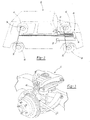
- FIG 2 is a perspective view of the vehicle 10 shown in phantom lines including an anti-rollover brake system 40 in accordance with the present invention.
- the vehicle 10 has a pair of front wheels 42 and 44 and a pair of rear wheels 46 and 48 shown in phantom lines in Figure 2.
- the brake system 40 includes a set of brakes 50, 52, 54, and 56, a sensor 58, and a control 60.
- the brakes 50, 52, 54, and 56 apply pressure to resist the rotation of the wheels 42, 44, 46, and 48 respectively.
- the sensor 58 produces a rollover signal in response to a predetermined force urging the vehicle 10 to rollover.
- the sensor 58 is designed to produce the rollover signal when the vehicle 10 is steered into a sharp turn which, if continued, will induce a friction rollover of the vehicle 10.
- the sensor 58 produces the rollover signal in response to a lateral acceleration of the center of mass of the vehicle 10 urging the vehicle 10 to rollover.
- the control 60 actuates the brakes 50, 52, 54, and 56 in a predetermined program in response to the rollover signal. Similar to conventional traction control brake systems, the control 60 must be capable of actuating the brakes 50, 52, 54, and 56 without the depression of a brake pedal. In conventional power assisted brake systems, engine vacuum or hydraulic power from a power steering pump is used to apply the brakes. In a preferred embodiment of the present invention, the brake control 60 is also capable of actuating each brake 50, 52, 54, and 56 independently.
- the senor 58 consists of an accelerometer for measuring a lateral acceleration of the vehicle 10.
- the sensor 58 is an instrument for measuring the body roll angle of the vehicle 10.
- the instrument used to measure the body roll angle of the vehicle 10 may consist of an accelerometer, a gyroscope, a roll rate sensor, or other like sensor.
- the vehicle 10 includes a pair of rebound bumpers positioned on opposite sides of the vehicle 10 near a wheel 42 or 46 and 44 or 48.
- the sensor 58 consists of a pair of switches for signaling compression of either of the rebound bumpers.
- a fragmentary perspective view of the vehicle 10 including one rebound bumper 62 having an integral switch (not shown) for producing the rollover signal in accordance with the present invention is shown in Figure 3.
- the brake control 60 is capable of actuating all four brakes 50, 52, 54, and 56 in accordance with a predetermined program.
- the control 60 is programmed to actuate both front brakes 50 and 52 in response to the rollover signal.
- the control 60 is programmed to actuate one of the front brakes 50 or 52 based upon the direction of the predetermined force. Specifically, the control 60 will brake the most heavily loaded front wheel 42 or 44. If the sensor 58 is an accelerometer measuring lateral acceleration, then the control 60 will actuate the front brake 50 or 52 in the direction opposite the measured lateral acceleration.
- the control 60 will actuate the front brake 50 or 52 in the direction of the roll. If the sensor 58 is a rebound bumper compression switch signaling wheel lift, then the control 60 will actuate the front brake 50 or 52 opposite the signaling or lifted wheel 42, 44, 46, or 48. To increase the ability to steer the vehicle 10 out of the turn, the control 60 is also capable of releasing or deactuating any actuated brake 50, 52, 54, or 56.
- the control 60 can actuate the brakes 50, 52, 54, and 56 to apply a maximum amount of brake pressure to resist the rotation of the wheels 42, 44, 46, and 48 respectively. Typically, a maximum amount of brake pressure would "lock” the braked wheel 42, 44, 46, or 48. In a preferred embodiment of the present invention, the control 60 actuates the brakes 50, 52, 54, and 56 to apply an amount of brake pressure proportional to the measured lateral acceleration of the vehicle 10. Typically. a proportional amount of brake pressure would not "lock” any wheel 42, 44, 46, or 48 during the brake actuation and, thereby, increase the ability to steer the vehicle 10 out of the turn.
- a method for preventing the rollover of a vehicle 10 having wheels 42, 44, 46, and 48 is disclosed.
- the order of the steps of the method is not important to achieving the objects of the present invention.
- the method may be performed in software, hardware, or a combination of both as in the preferred embodiment of the invention.
- the steps of the method include: providing a set of brakes 50, 52, 54, and 56 for applying pressure to resist the rotation of the wheels 42, 44, 46, and 48 of the vehicle 10; providing a sensor 58 for sensing an impending rollover condition; providing a control 60 for actuating the brakes 50, 52, 54, and 56; sensing an impending rollover condition; and braking the wheels 42, 44, 46, and 48 of the vehicle 10 in response to sensing the impending rollover condition.
- the method may further include the step of determining a critical amount of force to roll the vehicle 10 over during a turn. Accordingly, the step of sensing the impending rollover condition may then be further defined as measuring a predetermined amount of force less than the critical amount of force and the step of braking the wheels 42, 44, 46, and 48 may be further defined as braking the wheels 42, 44, 46, and 48 in response to measuring the predetermined amount of force.
- the critical amount of force to roll the vehicle over would be .8 g's and the predetermined amount of force would be an amount less than the critical amount of force (.8 g's), such as .75 g's. Therefore, at a lateral acceleration of .75 g's, the control 58 would actuate the appropriate brakes.
- the step of providing the sensor 58 is further defined as providing an accelerometer for measuring the amount of lateral acceleration placed on the center of mass of the vehicle 10. Accordingly, the step of sensing the impending rollover condition may then be further defined as measuring a predetermined critical amount of lateral acceleration placed on the center of mass of the vehicle 10 and the step of braking the wheels 42, 44, 46, and 48 may be further defined as braking the wheels 42, 44, 46, and 48 in response to measuring the predetermined critical amount of lateral acceleration placed on the center of gravity of the vehicle 10.
- the vehicle 10 includes a pair of rebound bumpers 62 positioned near a wheel 42 or 46 and 44 or 48 on opposite sides of the vehicle 10 and the.
- step of providing the sensor 58 is further defined as providing a switch for signaling compression of either of the rebound bumpers 62. Accordingly, the step of sensing an impending rollover condition may then be further defined as sensing compression of either of the rebound bumpers 62 and the step of braking the wheels 42, 44, 46, and 48 may be further defined as braking the wheels 42, 44, 46, and 48 in response to sensing compression of either of the rebound bumpers 62.
- the step of providing the sensor 58 is further defined as providing an accelerometer, a gyroscope, or a roll rate sensor to measure the roll angle or the vehicle 10. Accordingly, the step of sensing the impending rollover condition may then be further defined as measuring a predetermined critical roll angle of the vehicle 10 and the step of braking the vehicle 10 may be further defined as braking the vehicle 10 in response to measuring the predetermined critical roll angle.
- the step of braking the wheels 42, 44, 46, and 48 may be further defined as applying a maximum amount of pressure to the wheels 42, 44, 46, and 48 or applying an amount of pressure to the wheels 42, 44, 46, and 48 proportional to the lateral acceleration placed on the center of gravity of the vehicle 10, rebound bumper compression, or roll angle.
- the step of braking the wheels 42, 44, 46, and 48 may be further defined as braking the front wheels 42 and 44.
- the method may further include the step of determining which front wheel 42 or 44 is loaded with the largest amount of lateral force. Accordingly. the step of braking the wheels 42, 44, 46, and 48 may then be further defined as braking the front wheel 42 or 44 loaded with the largest amount of lateral force.
Landscapes
- Engineering & Computer Science (AREA)
- Mechanical Engineering (AREA)
- Transportation (AREA)
- Regulating Braking Force (AREA)
Abstract
Description
Claims (23)
- A brake system (40) for a vehicle having front wheels (42, 44), the system comprising:a set of front brakes (50, 52) for applying pressure to resist the rotation of the front wheels (42, 44);a sensor (58) for establishing at least one of a lateral acceleration or a body roll angle of the vehicle, for producing a rollover signal in response to a predetermined force urging the vehicle to rollover; anda control (60) for actuating said front set of brakes (50, 52) in a predetermined program in response to said rollover signal.
- A brake system (40) as set forth in claim 1 wherein said predetermined force is proportional to the lateral acceleration of the vehicle.
- A brake system (40) as set forth in claim 1 wherein said control (60) actuates said front-set of brakes (50, 52) to apply a maximum amount of pressure.
- A brake system (40) as set forth in claim 2 wherein said control (60) actuates said front set of brakes (50, 52) to apply an amount of pressure proportional to said lateral acceleration.
- A brake system (40) as set forth in claim 1 wherein said sensor (58) comprises an accelerometer for measuring lateral acceleration of the vehicle.
- A brake system (40) as set forth in claim 1 wherein said sensor (58) comprises an instrument for measuring the roll angle of the vehicle.
- A brake system (40) as set forth in claim 6 wherein said instrument comprises at least one of an accelerometer, a gyroscope, a roll rate sensor, and sensors measuring the distances between the vehicle and the wheels.
- A method for preventing a rollover of a vehicle (10) having at least a pair of front wheels (42, 44), the steps of the method comprising:providing a set of front brakes (50, 52) for applying pressure to resist the rotation of each of the front wheels (42, 44);providing a sensor (58) for sensing an impending rollover condition by establishing at least one of a lateral acceleration or a body roll angle of the vehicle;providing a control (60) for actuating said set of front brakes (50, 52);sensing an impending rollover condition; andactuating said set of front brakes (50, 52),braking said pair of front wheels (42, 44) of the vehicle (10) in response to sensing the impending rollover condition, said control (60) acting independently of other vehicle control systems.
- A method as set forth in claim 8 including the step of determining a critical amount of force to roll the vehicle over during a turn prior to the step of sensing the impending rollover condition.
- A method as set forth in claim 9 wherein the step of sensing the impending rollover condition is further defined as establishing a predetermined amount of force less than the critical amount of force.
- A method as set forth in claim 10 wherein the step of braking said pair of front wheels (42, 44) is further defined as braking said pair of front wheels (42, 44) in response to measuring the predetermined amount of force.
- A method as set forth in claim 8 wherein the step of providing the sensor is further defined as providing an accelerometer for measuring said lateral acceleration.
- A method as set forth in claim 12 wherein the step of sensing the impending rollover condition is further defined as measuring a predetermined critical amount of lateral acceleration placed on the centre of mass of the vehicle (10).
- A method as set forth in claim 13 wherein the step of braking said pair of front wheels (42, 44) is further defined as braking said pair of front wheels (42, 44) in response to measuring the predetermined critical amount of lateral acceleration placed on the centre of gravity of the vehicle (10).
- A method as set forth in claim 8 wherein the step of providing the sensor is further defined as providing one of an accelerometer, a gyroscope, a roll rate sensor, and sensors measuring the distance between the vehicle (10) and the wheels (42, 44, 46, 48) to measure the roll angle of the vehicle (10).
- A method as set forth in claim 15 wherein the step of sensing the impending rollover condition is further defined as measuring a predetermined critical roll angle of the vehicle (10).
- A method as set forth in claim 16 wherein the step of braking said pair of front wheels (42, 44) of the vehicle (10) is further defined as braking said pair of front wheels (42, 44) of the vehicle (10) in response to measuring the predetermined critical roll angle.
- A method as set forth in claim 8 wherein the step of braking said pair of front wheels (42, 44) is further defined as applying a maximum amount of pressure to said set of front brakes (50, 52).
- A method as set forth in claim 12 wherein the step of braking said pair of front wheels (42, 44) is further defined as applying an amount of pressure to said set of front brakes (52, 54) proportional to the lateral acceleration placed on the centre of gravity of the vehicle (10).
- A brake system (40) for a vehicle having front and rear wheels (42, 44, 46, 48), the system comprising:a set of brakes (50, 52, 54, 56) for applying pressure to resist the rotation of the front and rear wheels, said set of brakes including a front set of brakes (50, 52) for applying pressure to resist the rotation of said front wheels and a rear set of brakes (54, 56) for applying pressure to resist the rotation of said rear wheels;a sensor (58) for establishing an operating parameter of said vehicle, the operating parameter being indicative of a force urging the vehicle to rollover, and for responsively producing a rollover signal in response to a predetermined force urging the vehicle to rollover; anda control (60) for actuating said front set of brakes (50, 52) in a predetermined program in response to said rollover signal.
- A method for preventing a rollover of a vehicle (10) having at least a pair of front wheels (42, 44) and a pair of rear wheels (46, 48), the steps of the method comprising:providing a set of front brakes (50, 52) for applying pressure to resist the rotation of each of the front wheels (42, 44);providing a sensor (58) for establishing an impending rollover condition by measuring an operating parameter of the vehicle;providing a control (60) for actuating said set of front brakes (50, 52);sensing an impending rollover condition; andactuating said set of front brakes (50, 52),braking said pair of front wheels (42, 44) of the vehicle (10) in response to sensing the impending rollover condition, said control (60) acting independently of other vehicle control systems.
- A brake system (40) for a vehicle (10) having pair of front wheels (42, 44), the system (40) comprising:a set of front brakes (50, 52) for applying pressure to resist the rotation of the front wheels (42, 44);a sensor (58) for measuring a roll angle of the vehicle (10), and producing a rollover signal, the sensor (58) including at least one of an accelerometer, a gyroscope, a roll rate sensor, and sensors measuring the distance between the vehicle and the wheels; anda control (60) for actuating at least one of said front set of brakes (50, 52) in a predetermined program in response to said rollover signal and based upon the direction of said predetermined force.
- A method for preventing a rollover of a vehicle (10) having wheels (42, 44, 46, 48), comprising the steps of:providing a set of brakes (50, 52, 54, 56) for applying pressure to resist rotation of the respective wheels;providing a sensor (58) for sensing an impending rollover condition, the sensor (58) including at least one of an accelerometer, a gyroscope, a roll rate sensor, and sensors measuring the distance between the vehicle and the wheelsproviding a control (60) for actuating the brakes (50, 52, 54, 56);sensing an impending rollover condition, the rollover condition being defined by a predetermined critical roll angle of the vehicle (10); and,braking the wheels (42, 44, 46, 48) of the vehicle (10) in response to sensing the impending rollover condition.
Applications Claiming Priority (5)
| Application Number | Priority Date | Filing Date | Title |
|---|---|---|---|
| US5148297P | 1997-07-01 | 1997-07-01 | |
| US51482P | 1997-07-01 | ||
| US5630297P | 1997-09-03 | 1997-09-03 | |
| US56302P | 1997-09-03 | ||
| EP98933042A EP0991543B1 (en) | 1997-07-01 | 1998-06-30 | Anti-rollover brake system |
Related Parent Applications (1)
| Application Number | Title | Priority Date | Filing Date |
|---|---|---|---|
| EP98933042A Division EP0991543B1 (en) | 1997-07-01 | 1998-06-30 | Anti-rollover brake system |
Publications (3)
| Publication Number | Publication Date |
|---|---|
| EP1375230A2 true EP1375230A2 (en) | 2004-01-02 |
| EP1375230A3 EP1375230A3 (en) | 2004-01-07 |
| EP1375230B1 EP1375230B1 (en) | 2007-03-21 |
Family
ID=29718611
Family Applications (1)
| Application Number | Title | Priority Date | Filing Date |
|---|---|---|---|
| EP03077662A Revoked EP1375230B1 (en) | 1997-07-01 | 1998-06-30 | Anti-rollover brake system |
Country Status (1)
| Country | Link |
|---|---|
| EP (1) | EP1375230B1 (en) |
Cited By (2)
| Publication number | Priority date | Publication date | Assignee | Title |
|---|---|---|---|---|
| CN109952215A (en) * | 2017-06-30 | 2019-06-28 | 深圳市大疆创新科技有限公司 | Walk battlebus and the chassis for walking battlebus |
| CN110775046A (en) * | 2019-10-22 | 2020-02-11 | 浙江万安科技股份有限公司 | A vehicle anti-rollover control system and anti-rollover control method |
Family Cites Families (11)
| Publication number | Priority date | Publication date | Assignee | Title |
|---|---|---|---|---|
| JPS58152793A (en) * | 1982-03-05 | 1983-09-10 | ティー・シー・エム株式会社 | Device for preventing turning-sideways of transport car |
| JPS63116918A (en) * | 1986-11-05 | 1988-05-21 | Kayaba Ind Co Ltd | Roll control mechanism |
| JPH01101238A (en) * | 1987-10-14 | 1989-04-19 | Matsushita Electric Ind Co Ltd | Speed control device |
| US4998593A (en) * | 1989-03-31 | 1991-03-12 | Aisin Seiki Kabushiki Kaisha | Steering and brake controlling system |
| DE4227886A1 (en) * | 1992-08-22 | 1994-02-24 | Sel Alcatel Ag | Inclinometer for vehicle with body - contains inertial system or fibre optical gyroscope |
| DE4342732A1 (en) * | 1993-12-15 | 1995-06-22 | Anton Ellinghaus Maschinenfabr | Tilt sensor for tanker vehicle |
| DE19602879C1 (en) * | 1996-01-29 | 1997-08-07 | Knorr Bremse Systeme | Method for detecting the risk of a vehicle tipping over |
| DE19655388B4 (en) * | 1996-08-16 | 2008-08-14 | Daimler Ag | Vehicle dynamics control system and method |
| JPH10119743A (en) * | 1996-10-23 | 1998-05-12 | Aisin Seiki Co Ltd | Vehicle motion control device |
| DE19751891A1 (en) * | 1997-11-22 | 1999-05-27 | Bosch Gmbh Robert | Control method for vehicle with tendency to tip or tilt, e.g. lorries or wagons |
| EP1040033B1 (en) * | 1997-12-16 | 2005-04-06 | Continental Teves AG & Co. oHG | Method for improving tilt stability in a motor vehicle |
-
1998
- 1998-06-30 EP EP03077662A patent/EP1375230B1/en not_active Revoked
Cited By (3)
| Publication number | Priority date | Publication date | Assignee | Title |
|---|---|---|---|---|
| CN109952215A (en) * | 2017-06-30 | 2019-06-28 | 深圳市大疆创新科技有限公司 | Walk battlebus and the chassis for walking battlebus |
| CN110775046A (en) * | 2019-10-22 | 2020-02-11 | 浙江万安科技股份有限公司 | A vehicle anti-rollover control system and anti-rollover control method |
| CN110775046B (en) * | 2019-10-22 | 2023-02-17 | 浙江万安科技股份有限公司 | A vehicle anti-rollover control system and anti-rollover control method |
Also Published As
| Publication number | Publication date |
|---|---|
| EP1375230A3 (en) | 2004-01-07 |
| EP1375230B1 (en) | 2007-03-21 |
Similar Documents
| Publication | Publication Date | Title |
|---|---|---|
| US6065558A (en) | Anti-rollover brake system | |
| JP3480930B2 (en) | Driving method of automobile with braking device | |
| US6349247B1 (en) | Method and device for stabilizing a motor vehicle in order to prevent it from rolling over | |
| US6438464B1 (en) | Method and device for detecting the overturning hazard of a motor vehicle | |
| US6756890B1 (en) | Method and apparatus for stabilizing a vehicle in the presence of a tilt tendency | |
| US6498977B2 (en) | Device and method for stabilizing a combination of a tractor vehicle and at least one semitrailer or trailer | |
| US6554293B1 (en) | Method for improving tilt stability in a motor vehicle | |
| Palkovics et al. | Roll-over prevention system for commercial vehicles–additional sensorless function of the electronic brake system | |
| JP3563869B2 (en) | Engine output control device | |
| JP3425997B2 (en) | How to brake the vehicle wheels | |
| US6681167B2 (en) | Vehicle chassis control with coordinated brake and steering control on split coefficient surface | |
| US6178368B1 (en) | Roll control device of vehicles with tracing of turning course | |
| US20020059023A1 (en) | Rolling control apparatus and method of vehicle | |
| JPH11170992A (en) | Vehicle rollover prevention device | |
| US20060158031A1 (en) | Method and system for controlling the driving stability of a vehicle and use of said system | |
| JPH11271045A (en) | Method and apparatus for determining value representing height of center of gravity of vehicle | |
| US20010032043A1 (en) | Device and method for stabilizing a combination of a tractor vehicle and at least one semitrailer or trailer | |
| JP2004509005A (en) | How to evaluate the risk of vehicle overturn | |
| JP2001180468A (en) | Method of preventing turnover of vehicle | |
| US6527076B1 (en) | Device and method for limiting a backward rolling speed of a motor vehicle | |
| SE512829C2 (en) | Device for preventing incipient tipping forward motion of a vehicle | |
| US20080133101A1 (en) | Method and Device for Suppressing a Lateral Rollover Tendency of a Vehicle | |
| US20040199320A1 (en) | Drive system changing device and method/program thereof | |
| JP3705077B2 (en) | Vehicle motion control device | |
| EP1375230B1 (en) | Anti-rollover brake system |
Legal Events
| Date | Code | Title | Description |
|---|---|---|---|
| PUAI | Public reference made under article 153(3) epc to a published international application that has entered the european phase |
Free format text: ORIGINAL CODE: 0009012 |
|
| PUAL | Search report despatched |
Free format text: ORIGINAL CODE: 0009013 |
|
| 17P | Request for examination filed |
Effective date: 20030926 |
|
| AC | Divisional application: reference to earlier application |
Ref document number: 0991543 Country of ref document: EP Kind code of ref document: P |
|
| AK | Designated contracting states |
Kind code of ref document: A2 Designated state(s): AT BE CH CY DE DK ES FI FR GB GR IE IT LI LU MC NL PT SE |
|
| AK | Designated contracting states |
Kind code of ref document: A3 Designated state(s): AT BE CH CY DE DK ES FI FR GB GR IE IT LI LU MC NL PT SE |
|
| AKX | Designation fees paid |
Designated state(s): AT BE CH CY DE DK ES FI FR GB GR IE IT LI LU MC NL PT SE |
|
| 17Q | First examination report despatched |
Effective date: 20040827 |
|
| GRAP | Despatch of communication of intention to grant a patent |
Free format text: ORIGINAL CODE: EPIDOSNIGR1 |
|
| GRAS | Grant fee paid |
Free format text: ORIGINAL CODE: EPIDOSNIGR3 |
|
| GRAA | (expected) grant |
Free format text: ORIGINAL CODE: 0009210 |
|
| RAP1 | Party data changed (applicant data changed or rights of an application transferred) |
Owner name: DYNAMOTIVE, L.L.C. |
|
| AC | Divisional application: reference to earlier application |
Ref document number: 0991543 Country of ref document: EP Kind code of ref document: P |
|
| AK | Designated contracting states |
Kind code of ref document: B1 Designated state(s): AT BE CH CY DE DK ES FI FR GB GR IE IT LI LU MC NL PT SE |
|
| PG25 | Lapsed in a contracting state [announced via postgrant information from national office to epo] |
Ref country code: LI Free format text: LAPSE BECAUSE OF FAILURE TO SUBMIT A TRANSLATION OF THE DESCRIPTION OR TO PAY THE FEE WITHIN THE PRESCRIBED TIME-LIMIT Effective date: 20070321 Ref country code: FI Free format text: LAPSE BECAUSE OF FAILURE TO SUBMIT A TRANSLATION OF THE DESCRIPTION OR TO PAY THE FEE WITHIN THE PRESCRIBED TIME-LIMIT Effective date: 20070321 Ref country code: CH Free format text: LAPSE BECAUSE OF FAILURE TO SUBMIT A TRANSLATION OF THE DESCRIPTION OR TO PAY THE FEE WITHIN THE PRESCRIBED TIME-LIMIT Effective date: 20070321 Ref country code: BE Free format text: LAPSE BECAUSE OF FAILURE TO SUBMIT A TRANSLATION OF THE DESCRIPTION OR TO PAY THE FEE WITHIN THE PRESCRIBED TIME-LIMIT Effective date: 20070321 |
|
| REG | Reference to a national code |
Ref country code: GB Ref legal event code: FG4D |
|
| REG | Reference to a national code |
Ref country code: CH Ref legal event code: EP |
|
| REF | Corresponds to: |
Ref document number: 69837408 Country of ref document: DE Date of ref document: 20070503 Kind code of ref document: P |
|
| REG | Reference to a national code |
Ref country code: IE Ref legal event code: FG4D |
|
| REG | Reference to a national code |
Ref country code: SE Ref legal event code: TRGR |
|
| PG25 | Lapsed in a contracting state [announced via postgrant information from national office to epo] |
Ref country code: PT Free format text: LAPSE BECAUSE OF FAILURE TO SUBMIT A TRANSLATION OF THE DESCRIPTION OR TO PAY THE FEE WITHIN THE PRESCRIBED TIME-LIMIT Effective date: 20070821 |
|
| ET | Fr: translation filed | ||
| REG | Reference to a national code |
Ref country code: CH Ref legal event code: PL |
|
| REG | Reference to a national code |
Ref country code: ES Ref legal event code: FG2A Ref document number: 2285039 Country of ref document: ES Kind code of ref document: T3 |
|
| PLBI | Opposition filed |
Free format text: ORIGINAL CODE: 0009260 |
|
| PLBI | Opposition filed |
Free format text: ORIGINAL CODE: 0009260 |
|
| 26 | Opposition filed |
Opponent name: ROBERT BOSCH GMBH Effective date: 20071211 |
|
| PG25 | Lapsed in a contracting state [announced via postgrant information from national office to epo] |
Ref country code: DK Free format text: LAPSE BECAUSE OF FAILURE TO SUBMIT A TRANSLATION OF THE DESCRIPTION OR TO PAY THE FEE WITHIN THE PRESCRIBED TIME-LIMIT Effective date: 20070321 Ref country code: MC Free format text: LAPSE BECAUSE OF NON-PAYMENT OF DUE FEES Effective date: 20070630 |
|
| PLAX | Notice of opposition and request to file observation + time limit sent |
Free format text: ORIGINAL CODE: EPIDOSNOBS2 |
|
| PLAF | Information modified related to communication of a notice of opposition and request to file observations + time limit |
Free format text: ORIGINAL CODE: EPIDOSCOBS2 |
|
| 26 | Opposition filed |
Opponent name: ROBERT BOSCH GMBH Effective date: 20071211 Opponent name: LUCAS AUTOMOTIVE GMBH Effective date: 20071221 |
|
| NLR1 | Nl: opposition has been filed with the epo |
Opponent name: ROBERT BOSCH GMBH |
|
| NLR1 | Nl: opposition has been filed with the epo |
Opponent name: LUCAS AUTOMOTIVE GMBH Opponent name: ROBERT BOSCH GMBH |
|
| PG25 | Lapsed in a contracting state [announced via postgrant information from national office to epo] |
Ref country code: GR Free format text: LAPSE BECAUSE OF FAILURE TO SUBMIT A TRANSLATION OF THE DESCRIPTION OR TO PAY THE FEE WITHIN THE PRESCRIBED TIME-LIMIT Effective date: 20070622 |
|
| PLAF | Information modified related to communication of a notice of opposition and request to file observations + time limit |
Free format text: ORIGINAL CODE: EPIDOSCOBS2 |
|
| PLAF | Information modified related to communication of a notice of opposition and request to file observations + time limit |
Free format text: ORIGINAL CODE: EPIDOSCOBS2 |
|
| PLAF | Information modified related to communication of a notice of opposition and request to file observations + time limit |
Free format text: ORIGINAL CODE: EPIDOSCOBS2 |
|
| PLBB | Reply of patent proprietor to notice(s) of opposition received |
Free format text: ORIGINAL CODE: EPIDOSNOBS3 |
|
| PG25 | Lapsed in a contracting state [announced via postgrant information from national office to epo] |
Ref country code: IE Free format text: LAPSE BECAUSE OF NON-PAYMENT OF DUE FEES Effective date: 20080630 |
|
| PLBP | Opposition withdrawn |
Free format text: ORIGINAL CODE: 0009264 |
|
| PG25 | Lapsed in a contracting state [announced via postgrant information from national office to epo] |
Ref country code: CY Free format text: LAPSE BECAUSE OF FAILURE TO SUBMIT A TRANSLATION OF THE DESCRIPTION OR TO PAY THE FEE WITHIN THE PRESCRIBED TIME-LIMIT Effective date: 20070321 |
|
| NLS | Nl: assignments of ep-patents |
Owner name: DYNAMOTIVE IP, L.L.C. Effective date: 20090527 |
|
| PG25 | Lapsed in a contracting state [announced via postgrant information from national office to epo] |
Ref country code: LU Free format text: LAPSE BECAUSE OF NON-PAYMENT OF DUE FEES Effective date: 20070630 |
|
| PGFP | Annual fee paid to national office [announced via postgrant information from national office to epo] |
Ref country code: IE Payment date: 20071003 Year of fee payment: 10 |
|
| REG | Reference to a national code |
Ref country code: FR Ref legal event code: TP |
|
| RDAF | Communication despatched that patent is revoked |
Free format text: ORIGINAL CODE: EPIDOSNREV1 |
|
| APBM | Appeal reference recorded |
Free format text: ORIGINAL CODE: EPIDOSNREFNO |
|
| APBP | Date of receipt of notice of appeal recorded |
Free format text: ORIGINAL CODE: EPIDOSNNOA2O |
|
| APAH | Appeal reference modified |
Free format text: ORIGINAL CODE: EPIDOSCREFNO |
|
| APBQ | Date of receipt of statement of grounds of appeal recorded |
Free format text: ORIGINAL CODE: EPIDOSNNOA3O |
|
| RAP2 | Party data changed (patent owner data changed or rights of a patent transferred) |
Owner name: DYNAMOTIVE IP, LLC |
|
| PGFP | Annual fee paid to national office [announced via postgrant information from national office to epo] |
Ref country code: AT Payment date: 20120626 Year of fee payment: 15 |
|
| PGFP | Annual fee paid to national office [announced via postgrant information from national office to epo] |
Ref country code: DE Payment date: 20130626 Year of fee payment: 16 Ref country code: SE Payment date: 20130626 Year of fee payment: 16 Ref country code: GB Payment date: 20130626 Year of fee payment: 16 |
|
| PGFP | Annual fee paid to national office [announced via postgrant information from national office to epo] |
Ref country code: IT Payment date: 20130626 Year of fee payment: 16 |
|
| PGFP | Annual fee paid to national office [announced via postgrant information from national office to epo] |
Ref country code: NL Payment date: 20130626 Year of fee payment: 16 Ref country code: ES Payment date: 20130628 Year of fee payment: 16 |
|
| PGFP | Annual fee paid to national office [announced via postgrant information from national office to epo] |
Ref country code: FR Payment date: 20130719 Year of fee payment: 16 |
|
| REG | Reference to a national code |
Ref country code: DE Ref legal event code: R064 Ref document number: 69837408 Country of ref document: DE Ref country code: DE Ref legal event code: R103 Ref document number: 69837408 Country of ref document: DE |
|
| APBU | Appeal procedure closed |
Free format text: ORIGINAL CODE: EPIDOSNNOA9O |
|
| RDAG | Patent revoked |
Free format text: ORIGINAL CODE: 0009271 |
|
| STAA | Information on the status of an ep patent application or granted ep patent |
Free format text: STATUS: PATENT REVOKED |
|
| 27W | Patent revoked |
Effective date: 20131206 |
|
| GBPR | Gb: patent revoked under art. 102 of the ep convention designating the uk as contracting state |
Effective date: 20131206 |
|
| REG | Reference to a national code |
Ref country code: DE Ref legal event code: R107 Ref document number: 69837408 Country of ref document: DE Effective date: 20140403 |
|
| REG | Reference to a national code |
Ref country code: AT Ref legal event code: MA03 Ref document number: 357353 Country of ref document: AT Kind code of ref document: T Effective date: 20131206 |
|
| REG | Reference to a national code |
Ref country code: SE Ref legal event code: ECNC |