EP1375161A2 - Ink tank - Google Patents
Ink tank Download PDFInfo
- Publication number
- EP1375161A2 EP1375161A2 EP03076945A EP03076945A EP1375161A2 EP 1375161 A2 EP1375161 A2 EP 1375161A2 EP 03076945 A EP03076945 A EP 03076945A EP 03076945 A EP03076945 A EP 03076945A EP 1375161 A2 EP1375161 A2 EP 1375161A2
- Authority
- EP
- European Patent Office
- Prior art keywords
- bag
- casing
- wall
- ink tank
- bottom wall
- Prior art date
- Legal status (The legal status is an assumption and is not a legal conclusion. Google has not performed a legal analysis and makes no representation as to the accuracy of the status listed.)
- Granted
Links
- 230000006698 induction Effects 0.000 claims description 4
- 239000000463 material Substances 0.000 claims description 2
- 229910052751 metal Inorganic materials 0.000 claims description 2
- 239000002184 metal Substances 0.000 claims description 2
- 238000000034 method Methods 0.000 claims description 2
- 229920003002 synthetic resin Polymers 0.000 claims description 2
- 239000000057 synthetic resin Substances 0.000 claims description 2
- 239000007788 liquid Substances 0.000 description 5
- 238000004519 manufacturing process Methods 0.000 description 4
- 238000003466 welding Methods 0.000 description 3
- 230000037303 wrinkles Effects 0.000 description 3
- 229910052782 aluminium Inorganic materials 0.000 description 2
- XAGFODPZIPBFFR-UHFFFAOYSA-N aluminium Chemical compound [Al] XAGFODPZIPBFFR-UHFFFAOYSA-N 0.000 description 2
- 238000006073 displacement reaction Methods 0.000 description 2
- 239000004033 plastic Substances 0.000 description 2
- 229920003023 plastic Polymers 0.000 description 2
- 230000000717 retained effect Effects 0.000 description 2
- 230000015572 biosynthetic process Effects 0.000 description 1
- 239000003086 colorant Substances 0.000 description 1
- 238000010276 construction Methods 0.000 description 1
- 230000003247 decreasing effect Effects 0.000 description 1
- 230000000694 effects Effects 0.000 description 1
- 239000012530 fluid Substances 0.000 description 1
- 238000001746 injection moulding Methods 0.000 description 1
- 230000002093 peripheral effect Effects 0.000 description 1
Images



Classifications
-
- B—PERFORMING OPERATIONS; TRANSPORTING
- B41—PRINTING; LINING MACHINES; TYPEWRITERS; STAMPS
- B41J—TYPEWRITERS; SELECTIVE PRINTING MECHANISMS, i.e. MECHANISMS PRINTING OTHERWISE THAN FROM A FORME; CORRECTION OF TYPOGRAPHICAL ERRORS
- B41J2/00—Typewriters or selective printing mechanisms characterised by the printing or marking process for which they are designed
- B41J2/005—Typewriters or selective printing mechanisms characterised by the printing or marking process for which they are designed characterised by bringing liquid or particles selectively into contact with a printing material
- B41J2/01—Ink jet
- B41J2/17—Ink jet characterised by ink handling
- B41J2/175—Ink supply systems ; Circuit parts therefor
- B41J2/17503—Ink cartridges
- B41J2/17553—Outer structure
-
- B—PERFORMING OPERATIONS; TRANSPORTING
- B41—PRINTING; LINING MACHINES; TYPEWRITERS; STAMPS
- B41J—TYPEWRITERS; SELECTIVE PRINTING MECHANISMS, i.e. MECHANISMS PRINTING OTHERWISE THAN FROM A FORME; CORRECTION OF TYPOGRAPHICAL ERRORS
- B41J2/00—Typewriters or selective printing mechanisms characterised by the printing or marking process for which they are designed
- B41J2/005—Typewriters or selective printing mechanisms characterised by the printing or marking process for which they are designed characterised by bringing liquid or particles selectively into contact with a printing material
- B41J2/01—Ink jet
- B41J2/17—Ink jet characterised by ink handling
- B41J2/175—Ink supply systems ; Circuit parts therefor
- B41J2/17503—Ink cartridges
- B41J2/17513—Inner structure
-
- B—PERFORMING OPERATIONS; TRANSPORTING
- B41—PRINTING; LINING MACHINES; TYPEWRITERS; STAMPS
- B41J—TYPEWRITERS; SELECTIVE PRINTING MECHANISMS, i.e. MECHANISMS PRINTING OTHERWISE THAN FROM A FORME; CORRECTION OF TYPOGRAPHICAL ERRORS
- B41J2/00—Typewriters or selective printing mechanisms characterised by the printing or marking process for which they are designed
- B41J2/005—Typewriters or selective printing mechanisms characterised by the printing or marking process for which they are designed characterised by bringing liquid or particles selectively into contact with a printing material
- B41J2/01—Ink jet
- B41J2/17—Ink jet characterised by ink handling
- B41J2/175—Ink supply systems ; Circuit parts therefor
- B41J2/17503—Ink cartridges
- B41J2/17513—Inner structure
- B41J2002/17516—Inner structure comprising a collapsible ink holder, e.g. a flexible bag
Definitions
- the invention relates to an ink tank for an ink jet printer, comprising a casing having a bottom and a front wall with an opening formed therein, and a bag accommodated in said casing and collapsible into a sheet-like configuration, the bag having a top wall and a bottom wall, a front edge and a spout formed in a central region of said front edge and located at the position of said front wall opening.
- ink jet printers comprise an ink tank that has a comparatively large volume and is arranged stationarily in the frame of the printer and is connected to a movable ink jet device through a flexible tube.
- ink supply to the ink jet device is achieved either by sucking ink out of the tank or by supplying air into the space inside of the casing but outside of the bag, so that the bag is collapsed and the ink is squeezed out.
- the supply of ink from the tank to the ink jet device may be assisted by gravitational forces.
- ink supply might be achieved through gravitational forces alone, provided that the casing can be vented.
- the bag prevents the ink from leaking out of the casing and/or from being dried out through contact with the air in the casing.
- US-B-6,264,318 discloses an ink tank of the type indicated above, wherein the bag is disposed in the casing in an upright position, so that the front edge of the bag extends vertically.
- the spout and the corresponding opening in the front wall of the casing must be arranged above the bottom of the casing in a position corresponding to approximately half the height of the casing. This has the drawback that, when the ink is consumed and the bag is gradually emptied, the ink tends to be collected in the bottom portion of the bag, below the height of the spout, so that it is difficult to empty the bag completely, without any residues of ink remaining in the bag.
- US-A-6,105,821 discloses a tank in which the spout is formed near a corner of the bag, so that it may be disposed near the bottom of the casing.
- this type of bag is more difficult to manufacture because it is not easy to fix the spout in the seal between the walls of the bag and to seal it fluid-tightly when the spout is arranged near a corner of the bag.
- the walls of the bag will be stiffened by the presence of the spout, it is likely that a pocket is formed where remnants of ink may collect, even when the spout is arranged near the bottom edge of the bag.
- EP-A-1 013 449 discloses a tank in which the bag is disposed horizontally in a flat casing, so that a major portion of the ink may readily flow out even when the spout is arranged in a central region of the front edge of the bag. Then, however, the casing must have a relatively large width so as to accommodate the bag. This is particularly disadvantageous when a plurality of ink tanks for different colours are to be disposed side-by-side, in order to be on the same level.
- Another object of the invention is to provide a method for filling such an ink tank with liquid ink.
- the width of the top and bottom walls of the bag when measured in a flat, sheet-like configuration and in the direction of the front edge, is larger than the width of the casing, and the front wall opening is located near the bottom of the casing.
- the bag Since the width of the bag in its collapsed state is larger than the width of the casing, the bag can only be accommodated in the casing in a bent configuration, with at least one lateral portion of the bag being bent upwardly and supported at a side wall of the casing. As a result, the casing may have a comparatively small width, and the spout will be disposed in the lowest part of the bag and the casing even when the spout is arranged in the central region of the front edge of the bag.
- the bottom wall of the bag When the bag is filled with ink, the bottom wall of the bag is supported by the bottom of the casing, and, essentially, it is only the top wall of the bag that is displaced upwardly away from the bottom wall, so that the bag is expanded or inflated into an approximately cylindrical shape.
- the decreasing ink volume in the bag will allow the top wall of the bag to descend and to be flattened, and, finally, the top wall will once again match the upwardly concave shape of the bottom wall. Since at least one or preferably both lateral zones of the bottom wall of the bag remain bent upwardly, because they are supported by the side walls of the casing, the liquid ink will smoothly flow towards the centre line of the bag and into the spout under the effect of its own weight.
- the bag Since the possible deformations of the bag are constrained on the one hand by the side walls of the casing and on the other hand by the position of the spout and of the front wall opening of the casing, the bag is forced to essentially re-attain its original collapsed state, when it is empty. As a result, it is possible to refill the ink tank repeatedly, simply by introducing ink through the spout, and without any need for getting access to the interior of the casing.
- the top and bottom walls of the bag are interconnected at the front edge by an inwardly projecting fold the lower flap of which is sealed to the bottom wall, and the spout is incorporated in the seal between the bottom wall and this lower flap.
- the fold facilitates an upward displacement of the top wall of the bag, and the spout can remain in its position near the bottom of the casing while the bag is inflated to a relatively large volume.
- a similar fold is also provided at the rear edge of the bag, so that the volume of the bag in the inflated state can be increased further.
- the spout is formed by a rigid member, e.g. of plastics, which has a lens-shaped external contour that is sandwiched between the seal portions of the bottom wall and the lower flap of the fold.
- a rigid member e.g. of plastics
- This configuration facilitates the formation of a fluid-tight seal between the spout and the walls of the bag and has the further advantage that the bottom wall of the bag is forced to match the lens-shaped contour of the spout and is thereby stiffened in a channel-like configuration which permits the ink to flow out smoothly.
- the material of the bag shall on the one hand provide a sufficient air and liquid tightness of the bag and shall on the other hand be flexible enough to permit the bag to collapse completely.
- This can preferably be achieved by a multilayer construction of the walls of the bag, including at least one metal layer and at least one layer of synthetic resin.
- the wall of the bag may be a laminate with an inner layer of aluminum and outer layers of PE and PP, respectively.
- the bottom wall i.e. the wall forming the outer wall when the bag has a U-shaped configuration
- the top wall forming the inner wall of the U-shaped configuration has a greater stiffness than the top wall forming the inner wall of the U-shaped configuration.
- a collapsion induction fitment may be provided at the top wall of the casing so as to depend into the interior of the casing. Then, when the bag is expanded, its top wall will fit around this fitment, so that the bag retains its U-configuration even in the expanded state, although it then almost fills the entire volume of the casing. When the bag collapses, it will reliably retain the U-shaped configuration which it had already in the expanded state.
- the top edge of the U-shaped bag may reach up to the upper wall of the casing.
- the seals between the top wall and the bottom wall of the bag at the lateral edges thereof may be accommodated in the longitudinally extending top corners of the bag, and in the expanded state the bag will fill the volume of the casing almost completely.
- the top wall then has to pass around the fitment and will therefore form an internal fold accommodating the fitment. This internal fold absorbs the excess width of the top wall in relation to the U-shaped bottom wall, so that the top wall may smoothly mate the fitment without forming warps or wrinkles.
- the bag Since the expansion and collapsion behaviour of the bag is controlled by the walls of the casing and, as the case may be, by the collapsion induction fitment, the bag may be filled and emptied multiple times without any need for getting access to the interior of the casing, once the bag has been accommodated in the casing.
- the casing is therefore composed of two cup-shaped shells which are welded together at a seam surrounding the bag.
- the casing may be manufactured easily and at low costs, for example by injection molding the two shells and then welding them together after the bag has been inserted.
- the ink tank shown in figure 1 comprises a casing 10 made of plastic, for example, and a bag 12 accommodated in the casing 10.
- the casing 10 has essentially the shape of a parallelepiped, comprising side walls 14, 16, a bottom wall 18, a top wall 20, a front wall 22 and a rear wall 24.
- the bag 12 has a top wall 26 and a bottom wall 28 formed by flexible laminated sheets that are joined together, e. g. by welded seals 30, along their peripheral edge.
- the bag is collapsed into a sheet-like state and is accommodated in the casing 10 in a U-shaped configuration, with side portions 32, 34 of the bag being bent upwardly and supported at the side walls 14, 16 of the casing.
- a front edge 36 of the bag 12 is fluid-tightly connected to a spout 38 which penetrates an opening 38a in the front wall 22 of the casing 10.
- the spout 38 is arranged in a central region of the front edge 36 of the bag. Since the central portion of the bag lies on the bottom wall 18 of the casing 10, the spout 38 penetrates the front wall 22 of the casing in a position close to the bottom wall 18.
- the width of the bag 12 e.g. the width of the top and bottom walls 26, 28 as measured along the front edge 36, is larger than the width of the casing 10 and corresponds approximately to the sum of the width and the height of the casing 10.
- the upwardly bent side portions 32, 34 of the bag 12 reach up to a level which corresponds approximately to half the height of the casing 10.
- the bag 12 When liquid ink is filled into the bag 12 through the spout 38, the bag 12 is inflated or expanded into an approximately cylindrical or box-like configuration, as is shown in figure 2. This is mainly achieved by an upward displacement of the top wall 26 which then assumes an upwardly convex shape. As a result, the bag 12 almost completely fills the interior of the casing 10. Only the seal portions 30, where the top wall 26 and the bottom wall 28 of the bag are joined together, are retained in an upwardly bent configuration, because they are pressed against the side walls 14, 16 by the pressure of the liquid inside the bag.
- the casing 10 is vented, so that air may escape from the interior of the casing when the bag 12 is inflated.
- ink is drained through the spout 38
- the bag 12 will collapse again and air will enter into the volume inside of the casing 10 that is no longer occupied by the bag.
- the top wall 26 moves downwardly and attains again an upwardly concave shape and to finally match the U-shape of the bottom wall 28 once again, when the bag is emptied completely.
- the spout 38 is arranged in the lowest possible position near the bottom of the casing, the ink contained in the bag 12 is allowed to flow out smoothly under its own weight, and when the bag 12 collapses completely, no pockets filled with ink will remain inside of the bag.
- Figure 3 shows the bag 12 in the collapsed state and in a flat configuration in which the side portions of the top and bottom walls lie in the same plane as the central portions.
- the dimension W indicates the width of the bag 12 which is larger than the width of the casing 10.
- the front edge of the top wall 26 is slightly offset from the front edge of the bottom wall, and the front and bottom walls are interconnected by an inwardly projecting fold 40, as can best be seen in figure 4.
- a similar fold 42 is formed at the rear edge of the bag.
- the spout 38 is integrated in a seal 44 (figure 3) between the bottom wall 28 and a bottom flap 46 of the fold 40.
- the spout 38 is allowed to always retain its position near the bottom of the casing.
- the spout 38 has a lens-shaped retaining piece 48 which is smoothly fitted between the flap 46 and the bottom wall 28. This permits to form a fluid-tight seal between the spout 38 and the walls of the bag 12.
- the walls of the bag 12 such as the top wall 26 for example, comprise an outer layer 50 of PP, an intermediate layer 52 of aluminum and an inner layer 54 of PE.
- This laminated structure assures a high flexibility and at the same time a high air and fluid tightness of the bag.
- the inner layers 54 of PE permit to form the seals 38, 44 and the like by welding.
- additional diagonal seals 56 are formed in the corners of the bag, in order to prevent ink from being retained in the corner portions. These diagonal seals 56 interconnect the top wall 26 with the top flaps of the folds 40, 42 and will therefore not prevent the top wall 26 from being separated from the bottom wall 28.
- the spout 38 is formed with grooves 58 which may be engaged by the front wall 22 of the casing.
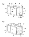
- Figure 7 shows an ink tank according to another embodiment, comprising a casing 10' and a bag 12'.
- the casing 10' is composed of two injection-molded cup-shaped shells or halves that are welded together at a weld seam 60 which passes through the side walls 14, 16, the bottom wall 18 and the top wall 20 of the casing and thus surrounds the bag 12' accommodated in the casing.
- the bag 12' is at first inserted into the casing half forming the opening 38a, and the spout 38 is fitted in the spout opening.
- the second casing half is fitted over the rear end of the bag 12' which projects out of the open rear end of the first half of the casing, and the two casing halves are welded together at the seam 60, e.g. by means of ultrasonic welding.
- the bag 12' according to the second embodiment is different from the bag 12 according to the first embodiment in that the total width W is larger, so that the top edges of the side portions 32, 34 reach up to the top wall 20 of the casing.
- a collapsion induction fitment 62 shaped as a rectangular plate is formed on the internal side of the top wall 20 of the casing 10'.
- the fitment 62 depends from the widthwise center of the top wall 20 into the interior of the casing to a level shortly above the spout 38, and it extends longitudinally from the front wall 22 of the casing to the position of the weld seam 60. Thus, the fitment 62 is only formed in one of the two casing halves.
- the bag 12' When the bag 12' is inflated, as shown in figure 8, it will fit around the fitment 62 and will, as a whole, retain a U-shaped configuration. As a result, the top wall 26 smoothly follows the contour of the fitment 62 and forms in internal fold which absorbs the excessive width. When the bag is collapsed again, the U-shape is preconfigured already, and this will reliably cause the bag to reassume the configuration shown in figure 7.
- the bottom wall 28 of the bag 12' is thicker and has a higher rigidity than the more flexible top wall 26.
- the stiffer bottom wall 28 will not warp or wrinkle but will be bent smoothly to engage the bottom wall 18 and the side walls 14, 16 of the casing.
- the greater flexibility of the top wall 26 permits the same to smoothly mate the shape of the top wall 20 and the fitment 62 of the casing in the expanded state of the bag and to smoothly mate the bottom wall 28 of the bag in the collapsed state.
Landscapes
- Ink Jet (AREA)
Abstract
Description
- The invention relates to an ink tank for an ink jet printer, comprising a casing having a bottom and a front wall with an opening formed therein, and a bag accommodated in said casing and collapsible into a sheet-like configuration, the bag having a top wall and a bottom wall, a front edge and a spout formed in a central region of said front edge and located at the position of said front wall opening.
- Several ink jet printers comprise an ink tank that has a comparatively large volume and is arranged stationarily in the frame of the printer and is connected to a movable ink jet device through a flexible tube. In operation, ink supply to the ink jet device is achieved either by sucking ink out of the tank or by supplying air into the space inside of the casing but outside of the bag, so that the bag is collapsed and the ink is squeezed out. The supply of ink from the tank to the ink jet device may be assisted by gravitational forces. As an alternative, ink supply might be achieved through gravitational forces alone, provided that the casing can be vented. In any case, the bag prevents the ink from leaking out of the casing and/or from being dried out through contact with the air in the casing.
- US-B-6,264,318 discloses an ink tank of the type indicated above, wherein the bag is disposed in the casing in an upright position, so that the front edge of the bag extends vertically. As a consequence, the spout and the corresponding opening in the front wall of the casing must be arranged above the bottom of the casing in a position corresponding to approximately half the height of the casing. This has the drawback that, when the ink is consumed and the bag is gradually emptied, the ink tends to be collected in the bottom portion of the bag, below the height of the spout, so that it is difficult to empty the bag completely, without any residues of ink remaining in the bag.
- US-A-6,105,821 discloses a tank in which the spout is formed near a corner of the bag, so that it may be disposed near the bottom of the casing. However, this type of bag is more difficult to manufacture because it is not easy to fix the spout in the seal between the walls of the bag and to seal it fluid-tightly when the spout is arranged near a corner of the bag. Moreover, since the walls of the bag will be stiffened by the presence of the spout, it is likely that a pocket is formed where remnants of ink may collect, even when the spout is arranged near the bottom edge of the bag. In addition, since the top regions of the bag are relatively far away from the spout, there is a risk that, when the bag collapses, a central portion of the bag is squeezed, so that remnants of ink remain enclosed in a top region. This is why this document proposes the use of a rigid flow inductor fitment disposed inside of the bag.
- EP-A-1 013 449 discloses a tank in which the bag is disposed horizontally in a flat casing, so that a major portion of the ink may readily flow out even when the spout is arranged in a central region of the front edge of the bag. Then, however, the casing must have a relatively large width so as to accommodate the bag. This is particularly disadvantageous when a plurality of ink tanks for different colours are to be disposed side-by-side, in order to be on the same level.
- It is an object of the invention to provide an ink tank that has a compact configuration, is easy to manufacture and nevertheless permits the ink to flow out smoothly and completely.
- Another object of the invention is to provide a method for filling such an ink tank with liquid ink.
- These objects are achieved with the features indicated in the independent claims.
- In the ink tank according to the invention, the width of the top and bottom walls of the bag, when measured in a flat, sheet-like configuration and in the direction of the front edge, is larger than the width of the casing, and the front wall opening is located near the bottom of the casing.
- Since the width of the bag in its collapsed state is larger than the width of the casing, the bag can only be accommodated in the casing in a bent configuration, with at least one lateral portion of the bag being bent upwardly and supported at a side wall of the casing. As a result, the casing may have a comparatively small width, and the spout will be disposed in the lowest part of the bag and the casing even when the spout is arranged in the central region of the front edge of the bag.
- When the bag is filled with ink, the bottom wall of the bag is supported by the bottom of the casing, and, essentially, it is only the top wall of the bag that is displaced upwardly away from the bottom wall, so that the bag is expanded or inflated into an approximately cylindrical shape. When the printer is operating and the ink is consumed gradually, the decreasing ink volume in the bag will allow the top wall of the bag to descend and to be flattened, and, finally, the top wall will once again match the upwardly concave shape of the bottom wall. Since at least one or preferably both lateral zones of the bottom wall of the bag remain bent upwardly, because they are supported by the side walls of the casing, the liquid ink will smoothly flow towards the centre line of the bag and into the spout under the effect of its own weight.
- Since the possible deformations of the bag are constrained on the one hand by the side walls of the casing and on the other hand by the position of the spout and of the front wall opening of the casing, the bag is forced to essentially re-attain its original collapsed state, when it is empty. As a result, it is possible to refill the ink tank repeatedly, simply by introducing ink through the spout, and without any need for getting access to the interior of the casing.
- Useful details of the invention are indicated in the dependant claims.
- Preferably, the top and bottom walls of the bag are interconnected at the front edge by an inwardly projecting fold the lower flap of which is sealed to the bottom wall, and the spout is incorporated in the seal between the bottom wall and this lower flap. The fold facilitates an upward displacement of the top wall of the bag, and the spout can remain in its position near the bottom of the casing while the bag is inflated to a relatively large volume. Preferably, a similar fold is also provided at the rear edge of the bag, so that the volume of the bag in the inflated state can be increased further.
- In a preferred embodiment, the spout is formed by a rigid member, e.g. of plastics, which has a lens-shaped external contour that is sandwiched between the seal portions of the bottom wall and the lower flap of the fold. This configuration facilitates the formation of a fluid-tight seal between the spout and the walls of the bag and has the further advantage that the bottom wall of the bag is forced to match the lens-shaped contour of the spout and is thereby stiffened in a channel-like configuration which permits the ink to flow out smoothly.
- The above-described features of the bag are useful even in situations in which the bag is accommodated in a casing having a larger width, so that the lateral portions of the bag need not be bent upwardly.
- The material of the bag shall on the one hand provide a sufficient air and liquid tightness of the bag and shall on the other hand be flexible enough to permit the bag to collapse completely. This can preferably be achieved by a multilayer construction of the walls of the bag, including at least one metal layer and at least one layer of synthetic resin. For example, the wall of the bag may be a laminate with an inner layer of aluminum and outer layers of PE and PP, respectively.
- In a preferred embodiment of the bag, the bottom wall, i.e. the wall forming the outer wall when the bag has a U-shaped configuration, has a greater stiffness than the top wall forming the inner wall of the U-shaped configuration. This has the advantage that the outer wall may smoothly engage the walls of the casing, essentially without forming wrinkles, whereas the greater flexibility of the inner wall permits the same to expand and collapse more easily. In the collapsed state, the inner wall will match the essentially smooth surface of the outer wall, so that no substantial pockets will be left within the bag.
- In order to assist the bag in collapsing in the desired U-shape, a collapsion induction fitment may be provided at the top wall of the casing so as to depend into the interior of the casing. Then, when the bag is expanded, its top wall will fit around this fitment, so that the bag retains its U-configuration even in the expanded state, although it then almost fills the entire volume of the casing. When the bag collapses, it will reliably retain the U-shaped configuration which it had already in the expanded state.
- In this embodiment, the top edge of the U-shaped bag may reach up to the upper wall of the casing. As a result, the seals between the top wall and the bottom wall of the bag at the lateral edges thereof may be accommodated in the longitudinally extending top corners of the bag, and in the expanded state the bag will fill the volume of the casing almost completely. The top wall then has to pass around the fitment and will therefore form an internal fold accommodating the fitment. This internal fold absorbs the excess width of the top wall in relation to the U-shaped bottom wall, so that the top wall may smoothly mate the fitment without forming warps or wrinkles.
- Since the expansion and collapsion behaviour of the bag is controlled by the walls of the casing and, as the case may be, by the collapsion induction fitment, the bag may be filled and emptied multiple times without any need for getting access to the interior of the casing, once the bag has been accommodated in the casing. In a preferred embodiment, the casing is therefore composed of two cup-shaped shells which are welded together at a seam surrounding the bag. As a result, the casing may be manufactured easily and at low costs, for example by injection molding the two shells and then welding them together after the bag has been inserted.
- Preferred embodiments of the invention will now be described in conjunction with the drawings, in which:
- Fig. 1
- is a schematic perspective view of an ink tank according to the invention in an empty state;
- Fig. 2
- is a perspective view of the ink tank in the completely filled state;
- Fig. 3
- is a plan view of a bag to be accommodated in the ink tank;
- Fig. 4
- is a sectional view taken along the line IV-IV in figure 3;
- Fig. 5
- is a sectional view taken along the line V-V in figure 3;
- Fig. 6
- is an enlarged cross section of a portion of the wall of the bag; and
- Figs. 7-9
- are views corresponding to Figures 1, 2 and 4 and showing a modified embodiment.
- The ink tank shown in figure 1 comprises a
casing 10 made of plastic, for example, and abag 12 accommodated in thecasing 10.
In the shown embodiment, thecasing 10 has essentially the shape of a parallelepiped, comprisingside walls bottom wall 18, atop wall 20, afront wall 22 and arear wall 24. Thebag 12 has atop wall 26 and abottom wall 28 formed by flexible laminated sheets that are joined together, e. g. by weldedseals 30, along their peripheral edge. In figure 1 the bag is collapsed into a sheet-like state and is accommodated in thecasing 10 in a U-shaped configuration, withside portions side walls front edge 36 of thebag 12 is fluid-tightly connected to aspout 38 which penetrates anopening 38a in thefront wall 22 of thecasing 10. Thespout 38 is arranged in a central region of thefront edge 36 of the bag. Since the central portion of the bag lies on thebottom wall 18 of thecasing 10, thespout 38 penetrates thefront wall 22 of the casing in a position close to thebottom wall 18. - The width of the
bag 12, e.g. the width of the top andbottom walls front edge 36, is larger than the width of thecasing 10 and corresponds approximately to the sum of the width and the height of thecasing 10. As a result, the upwardlybent side portions bag 12 reach up to a level which corresponds approximately to half the height of thecasing 10. - When liquid ink is filled into the
bag 12 through thespout 38, thebag 12 is inflated or expanded into an approximately cylindrical or box-like configuration, as is shown in figure 2. This is mainly achieved by an upward displacement of thetop wall 26 which then assumes an upwardly convex shape. As a result, thebag 12 almost completely fills the interior of thecasing 10. Only theseal portions 30, where thetop wall 26 and thebottom wall 28 of the bag are joined together, are retained in an upwardly bent configuration, because they are pressed against theside walls - It will be understood that the
casing 10 is vented, so that air may escape from the interior of the casing when thebag 12 is inflated. Conversely, when, in figure 2, ink is drained through thespout 38, thebag 12 will collapse again and air will enter into the volume inside of thecasing 10 that is no longer occupied by the bag. When thebag 12 collapses, thetop wall 26 moves downwardly and attains again an upwardly concave shape and to finally match the U-shape of thebottom wall 28 once again, when the bag is emptied completely. Since thespout 38 is arranged in the lowest possible position near the bottom of the casing, the ink contained in thebag 12 is allowed to flow out smoothly under its own weight, and when thebag 12 collapses completely, no pockets filled with ink will remain inside of the bag. - Figure 3 shows the
bag 12 in the collapsed state and in a flat configuration in which the side portions of the top and bottom walls lie in the same plane as the central portions. In figure 3, the dimension W indicates the width of thebag 12 which is larger than the width of thecasing 10. - At the
front edge 36 of thebag 12, the front edge of thetop wall 26 is slightly offset from the front edge of the bottom wall, and the front and bottom walls are interconnected by an inwardly projectingfold 40, as can best be seen in figure 4. Asimilar fold 42 is formed at the rear edge of the bag. These folds 40, 42 permit thetop wall 26 to be displaced upwardly relative to thebottom wall 28 over a large distance, so as to achieve a large volume of the bag. - It will be appreciated that the
spout 38 is integrated in a seal 44 (figure 3) between thebottom wall 28 and abottom flap 46 of thefold 40. Thus, thespout 38 is allowed to always retain its position near the bottom of the casing. - As is shown in figure 5, the
spout 38 has a lens-shapedretaining piece 48 which is smoothly fitted between theflap 46 and thebottom wall 28. This permits to form a fluid-tight seal between thespout 38 and the walls of thebag 12. - As is shown in figure 6, the walls of the
bag 12, such as thetop wall 26 for example, comprise anouter layer 50 of PP, anintermediate layer 52 of aluminum and aninner layer 54 of PE. This laminated structure assures a high flexibility and at the same time a high air and fluid tightness of the bag. Theinner layers 54 of PE permit to form theseals - As is shown in figure 3, additional
diagonal seals 56 are formed in the corners of the bag, in order to prevent ink from being retained in the corner portions. Thesediagonal seals 56 interconnect thetop wall 26 with the top flaps of thefolds top wall 26 from being separated from thebottom wall 28. - In order to hold the
bag 12 in position within thecasing 10, thespout 38 is formed withgrooves 58 which may be engaged by thefront wall 22 of the casing. - Figure 7 shows an ink tank according to another embodiment, comprising a casing 10' and a bag 12'.
- Here, the casing 10' is composed of two injection-molded cup-shaped shells or halves that are welded together at a
weld seam 60 which passes through theside walls bottom wall 18 and thetop wall 20 of the casing and thus surrounds the bag 12' accommodated in the casing. In the manufacturing process, the bag 12' is at first inserted into the casing half forming theopening 38a, and thespout 38 is fitted in the spout opening. Then, the second casing half is fitted over the rear end of the bag 12' which projects out of the open rear end of the first half of the casing, and the two casing halves are welded together at theseam 60, e.g. by means of ultrasonic welding. - Of course, this manufacturing process may also be applied to the
casing 10 shown in figures 1 and 2. - The bag 12' according to the second embodiment is different from the
bag 12 according to the first embodiment in that the total width W is larger, so that the top edges of theside portions top wall 20 of the casing. - When the bag 12' is inflated, the
top wall 26 thereof is lifted up to the top wall of the casing and has only to bridge the opposing edges of theside portions top wall 26 has essentially the same width as thebottom wall 28 of the bag, the width of the top wall would be too large in this state. In order to prevent thetop wall 26 from forming folds in an uncontrollable manner and in order to prevent the bag 12' to collapse in an uncontrollable way when it is emptied, acollapsion induction fitment 62 shaped as a rectangular plate is formed on the internal side of thetop wall 20 of the casing 10'. Thefitment 62 depends from the widthwise center of thetop wall 20 into the interior of the casing to a level shortly above thespout 38, and it extends longitudinally from thefront wall 22 of the casing to the position of theweld seam 60. Thus, thefitment 62 is only formed in one of the two casing halves. - When the bag 12' is inflated, as shown in figure 8, it will fit around the
fitment 62 and will, as a whole, retain a U-shaped configuration. As a result, thetop wall 26 smoothly follows the contour of thefitment 62 and forms in internal fold which absorbs the excessive width. When the bag is collapsed again, the U-shape is preconfigured already, and this will reliably cause the bag to reassume the configuration shown in figure 7. - In Figure 9, it can be seen that the
folds top wall 26 to be lifted in its entirety, when the bag is inflated, so that the bag may almost completely fill the interior of the casing 10'. - As is further shown in figure 9, the
bottom wall 28 of the bag 12' is thicker and has a higher rigidity than the more flexibletop wall 26. As a result, when the bag is accommodated in the casing 10', thestiffer bottom wall 28 will not warp or wrinkle but will be bent smoothly to engage thebottom wall 18 and theside walls top wall 26 permits the same to smoothly mate the shape of thetop wall 20 and thefitment 62 of the casing in the expanded state of the bag and to smoothly mate thebottom wall 28 of the bag in the collapsed state.
Claims (12)
- Ink tank for an ink jet printer, comprising a casing (10; 10') having a bottom wall (18) and a front wall (22) with an opening (38a) formed therein, and a bag (12; 12') accommodated in said casing (10; 10') and collapsible into a sheet-like configuration, the bag (12; 12') having a top wall (26), a bottom wall (28), a front edge (36) and a spout (38) formed in a central region of said front edge (36) and located at the position of said front wall opening (38a), characterised in that the width (W) of the top and bottom walls (26, 28) of the bag (12; 12'), when measured in a flat, sheet-like configuration and in the direction of the front edge (36), is larger than the width of the casing (10; 10'), and in that the front wall opening (38a) is located near the bottom wall (18) of the casing (10; 10').
- Ink tank according to claim 1, wherein the spout (38) is fixedly held in the opening (38a) of the front wall (22) of the casing.
- Ink tank according to claim 1 or 2, wherein the top wall (26) and the bottom wall (28) of the bag (12; 12') are interconnected by an inwardly projecting fold (40) at the front edge (36) of the bag, and the spout (38) is incorporated in a seal (44) between the bottom wall (28) and a lower flap (46) of the fold (40).
- Ink tank according to claim 3, wherein another inwardly projecting fold (42) interconnects the top wall (26) and the bottom wall (28) at a rear edge of the bag (12; 12').
- Ink tank according to claim 3 or 4, wherein the top wall (26) and the bottom wall (28) of the bag (12; 12') are directly interconnected by seals (30) extending along the lateral edges of the bag (12; 12').
- Ink tank according to any of the preceding claims, wherein the spout (38) has a retaining piece (48) which has a lens-shaped cross section and is inserted between wall portions (28, 46) of the bag (12; 12'), which form a seal (44).
- Ink tank according to any of the preceding claims, wherein the wall material of the bag (12; 12') has a laminated structure including at least two layers (50, 44) of synthetic resin with a metal layer (52) interposed therebetween.
- Ink tank according to any of the preceding claims, wherein the bottom wall (28) of the bag (12') is stiffer than the top wall (26).
- Ink tank according to any of the preceding claims, wherein the width of the bag (12') corresponds to the width of the casing (10') plus twice the height of the casing, and the bag (12') is accommodated in the casing (10') in a U-shaped configuration with two side portions (32, 34) being bent upwardly and reaching up into the vicinity of a top wall (20) of the casing (10').
- Ink tank according to claim 9, comprising a collapsion induction fitment (62) depending from the top wall (20) of the casing (10') and projecting into the interior of the casing.
- Ink tank according to any of the preceding claims, wherein the casing (10') is composed of two cup-shaped shells welded together at a weld seam (60) which surrounds the bag (12') accommodated in the casing.
- Method of filling an ink tank as claimed in claim 1, characterised in that the ink is introduced through the spout (38) into the bag (12; 12') when the latter is accommodated in the casing (10; 10') in a collapsed and bent state with at least one side portion (32, 34) of the bag being bent upwardly and supported at a side wall (14, 16) of the casing (10; 10'), and, by introducing the ink, the top wall (26) of the bag is displaced upwardly away from the bottom wall (28).
Priority Applications (1)
| Application Number | Priority Date | Filing Date | Title |
|---|---|---|---|
| EP20030076945 EP1375161B1 (en) | 2002-06-28 | 2003-06-24 | Ink tank |
Applications Claiming Priority (3)
| Application Number | Priority Date | Filing Date | Title |
|---|---|---|---|
| EP02077779 | 2002-06-28 | ||
| EP02077779 | 2002-06-28 | ||
| EP20030076945 EP1375161B1 (en) | 2002-06-28 | 2003-06-24 | Ink tank |
Publications (3)
| Publication Number | Publication Date |
|---|---|
| EP1375161A2 true EP1375161A2 (en) | 2004-01-02 |
| EP1375161A3 EP1375161A3 (en) | 2007-03-07 |
| EP1375161B1 EP1375161B1 (en) | 2008-09-17 |
Family
ID=29718290
Family Applications (1)
| Application Number | Title | Priority Date | Filing Date |
|---|---|---|---|
| EP20030076945 Expired - Lifetime EP1375161B1 (en) | 2002-06-28 | 2003-06-24 | Ink tank |
Country Status (1)
| Country | Link |
|---|---|
| EP (1) | EP1375161B1 (en) |
Cited By (3)
| Publication number | Priority date | Publication date | Assignee | Title |
|---|---|---|---|---|
| EP1510346A3 (en) * | 2003-08-08 | 2007-09-26 | Seiko Epson Corporation | Liquid container |
| WO2012086380A1 (en) * | 2010-12-20 | 2012-06-28 | Fujifilm Corporation | Printing liquid filled container and image forming apparatus |
| CN107379630A (en) * | 2017-08-29 | 2017-11-24 | 温州优比科实业有限公司 | Manage bag machine in a kind of infolding bottom |
Families Citing this family (1)
| Publication number | Priority date | Publication date | Assignee | Title |
|---|---|---|---|---|
| DE102022115378B3 (en) | 2022-06-21 | 2023-07-20 | Canon Production Printing Holding B.V. | Device, ink printing system and method for determining when an ink container is empty |
Citations (3)
| Publication number | Priority date | Publication date | Assignee | Title |
|---|---|---|---|---|
| EP1013449A2 (en) | 1998-12-24 | 2000-06-28 | Seiko Epson Corporation | Ink bag for ink jet type recording apparatus and package suitable for packing such ink bag |
| US6105821A (en) | 1997-11-10 | 2000-08-22 | Gr Advanced Materials Ltd | Dispensing container for highly viscous liquids |
| US6264318B1 (en) | 1999-02-10 | 2001-07-24 | Fuji Xerox Co., Ltd. | Ink-jet recording apparatus and ink storing device |
Family Cites Families (5)
| Publication number | Priority date | Publication date | Assignee | Title |
|---|---|---|---|---|
| JP2633875B2 (en) * | 1987-11-20 | 1997-07-23 | キヤノン株式会社 | ink cartridge |
| JPH05345423A (en) * | 1992-06-16 | 1993-12-27 | Canon Inc | Ink cartridge |
| DE19849567B4 (en) * | 1998-10-27 | 2004-02-12 | Tally Computerdrucker Gmbh | Ink printer with an exchangeable cartridge for ink liquid |
| JP3767334B2 (en) * | 2000-06-21 | 2006-04-19 | セイコーエプソン株式会社 | Ink cartridge for recording apparatus |
| US6250751B1 (en) * | 2000-03-28 | 2001-06-26 | Lexmark International, Inc. | Ink jet printer cartridge manufacturing method and apparatus |
-
2003
- 2003-06-24 EP EP20030076945 patent/EP1375161B1/en not_active Expired - Lifetime
Patent Citations (3)
| Publication number | Priority date | Publication date | Assignee | Title |
|---|---|---|---|---|
| US6105821A (en) | 1997-11-10 | 2000-08-22 | Gr Advanced Materials Ltd | Dispensing container for highly viscous liquids |
| EP1013449A2 (en) | 1998-12-24 | 2000-06-28 | Seiko Epson Corporation | Ink bag for ink jet type recording apparatus and package suitable for packing such ink bag |
| US6264318B1 (en) | 1999-02-10 | 2001-07-24 | Fuji Xerox Co., Ltd. | Ink-jet recording apparatus and ink storing device |
Cited By (7)
| Publication number | Priority date | Publication date | Assignee | Title |
|---|---|---|---|---|
| EP1510346A3 (en) * | 2003-08-08 | 2007-09-26 | Seiko Epson Corporation | Liquid container |
| US7677712B2 (en) | 2003-08-08 | 2010-03-16 | Seiko Epson Corporation | Liquid container having foldable portion |
| WO2012086380A1 (en) * | 2010-12-20 | 2012-06-28 | Fujifilm Corporation | Printing liquid filled container and image forming apparatus |
| CN103237661A (en) * | 2010-12-20 | 2013-08-07 | 富士胶片株式会社 | Printing liquid filled container and image forming apparatus |
| CN103237661B (en) * | 2010-12-20 | 2016-03-30 | 富士胶片株式会社 | Be filled with printed liquid build container and image forming apparatus |
| CN107379630A (en) * | 2017-08-29 | 2017-11-24 | 温州优比科实业有限公司 | Manage bag machine in a kind of infolding bottom |
| CN107379630B (en) * | 2017-08-29 | 2023-08-08 | 温州优比科实业有限公司 | Inner folding bottom bag arranging machine |
Also Published As
| Publication number | Publication date |
|---|---|
| EP1375161A3 (en) | 2007-03-07 |
| EP1375161B1 (en) | 2008-09-17 |
Similar Documents
| Publication | Publication Date | Title |
|---|---|---|
| US6874879B2 (en) | Ink tank | |
| EP0535869B1 (en) | Improvements in and relating to flexible containers | |
| EP0389257A1 (en) | Flexible pouch with reinforcement to facilitate pouring | |
| US7980410B2 (en) | Foldable bag and combination of a container and a bag and method for the use of this combination | |
| CA2476705A1 (en) | Liquid container | |
| MX2009000292A (en) | Container for fluids, insert and method of filling a container. | |
| KR102154539B1 (en) | Liquid storage container and method for folding same | |
| WO1996001775A1 (en) | Packaging pouch with stiffening air channels | |
| JP2708429B2 (en) | Cartridge container | |
| TWI682881B (en) | Paper inner container for replenishing liquid contents | |
| CN115397741A (en) | Bag and filling method | |
| EP1375161B1 (en) | Ink tank | |
| CN115279664B (en) | container | |
| JP2002053144A (en) | Cartridge type bag | |
| JP6911887B2 (en) | Storage container | |
| JP7365222B2 (en) | container | |
| JP4993884B2 (en) | Self-supporting bag | |
| KR100551511B1 (en) | Material Packaging Container | |
| US20040046844A1 (en) | Ink tank | |
| EP1375162B1 (en) | Ink tank for ink jet | |
| JP4641088B2 (en) | Cartridge type bag | |
| JP2017001684A (en) | Storage container | |
| JP2002052739A (en) | Cartridge type bag |
Legal Events
| Date | Code | Title | Description |
|---|---|---|---|
| PUAI | Public reference made under article 153(3) epc to a published international application that has entered the european phase |
Free format text: ORIGINAL CODE: 0009012 |
|
| AK | Designated contracting states |
Kind code of ref document: A2 Designated state(s): AT BE BG CH CY CZ DE DK EE ES FI FR GB GR HU IE IT LI LU MC NL PT RO SE SI SK TR |
|
| AX | Request for extension of the european patent |
Extension state: AL LT LV MK |
|
| PUAL | Search report despatched |
Free format text: ORIGINAL CODE: 0009013 |
|
| AK | Designated contracting states |
Kind code of ref document: A3 Designated state(s): AT BE BG CH CY CZ DE DK EE ES FI FR GB GR HU IE IT LI LU MC NL PT RO SE SI SK TR |
|
| AX | Request for extension of the european patent |
Extension state: AL LT LV MK |
|
| 17P | Request for examination filed |
Effective date: 20070907 |
|
| AKX | Designation fees paid |
Designated state(s): AT BE BG CH CY CZ DE DK EE ES FI FR GB GR HU IE IT LI LU MC NL PT RO SE SI SK TR |
|
| 17Q | First examination report despatched |
Effective date: 20071112 |
|
| GRAP | Despatch of communication of intention to grant a patent |
Free format text: ORIGINAL CODE: EPIDOSNIGR1 |
|
| GRAS | Grant fee paid |
Free format text: ORIGINAL CODE: EPIDOSNIGR3 |
|
| GRAA | (expected) grant |
Free format text: ORIGINAL CODE: 0009210 |
|
| AK | Designated contracting states |
Kind code of ref document: B1 Designated state(s): AT BE BG CH CY CZ DE DK EE ES FI FR GB GR HU IE IT LI LU MC NL PT RO SE SI SK TR |
|
| REG | Reference to a national code |
Ref country code: GB Ref legal event code: FG4D |
|
| REG | Reference to a national code |
Ref country code: CH Ref legal event code: EP |
|
| REG | Reference to a national code |
Ref country code: IE Ref legal event code: FG4D |
|
| REF | Corresponds to: |
Ref document number: 60323565 Country of ref document: DE Date of ref document: 20081030 Kind code of ref document: P |
|
| PG25 | Lapsed in a contracting state [announced via postgrant information from national office to epo] |
Ref country code: FI Free format text: LAPSE BECAUSE OF FAILURE TO SUBMIT A TRANSLATION OF THE DESCRIPTION OR TO PAY THE FEE WITHIN THE PRESCRIBED TIME-LIMIT Effective date: 20080917 Ref country code: AT Free format text: LAPSE BECAUSE OF FAILURE TO SUBMIT A TRANSLATION OF THE DESCRIPTION OR TO PAY THE FEE WITHIN THE PRESCRIBED TIME-LIMIT Effective date: 20080917 Ref country code: SI Free format text: LAPSE BECAUSE OF FAILURE TO SUBMIT A TRANSLATION OF THE DESCRIPTION OR TO PAY THE FEE WITHIN THE PRESCRIBED TIME-LIMIT Effective date: 20080917 |
|
| PG25 | Lapsed in a contracting state [announced via postgrant information from national office to epo] |
Ref country code: BE Free format text: LAPSE BECAUSE OF FAILURE TO SUBMIT A TRANSLATION OF THE DESCRIPTION OR TO PAY THE FEE WITHIN THE PRESCRIBED TIME-LIMIT Effective date: 20080917 |
|
| PG25 | Lapsed in a contracting state [announced via postgrant information from national office to epo] |
Ref country code: ES Free format text: LAPSE BECAUSE OF FAILURE TO SUBMIT A TRANSLATION OF THE DESCRIPTION OR TO PAY THE FEE WITHIN THE PRESCRIBED TIME-LIMIT Effective date: 20081228 Ref country code: BG Free format text: LAPSE BECAUSE OF FAILURE TO SUBMIT A TRANSLATION OF THE DESCRIPTION OR TO PAY THE FEE WITHIN THE PRESCRIBED TIME-LIMIT Effective date: 20081217 |
|
| PG25 | Lapsed in a contracting state [announced via postgrant information from national office to epo] |
Ref country code: SK Free format text: LAPSE BECAUSE OF FAILURE TO SUBMIT A TRANSLATION OF THE DESCRIPTION OR TO PAY THE FEE WITHIN THE PRESCRIBED TIME-LIMIT Effective date: 20080917 Ref country code: RO Free format text: LAPSE BECAUSE OF FAILURE TO SUBMIT A TRANSLATION OF THE DESCRIPTION OR TO PAY THE FEE WITHIN THE PRESCRIBED TIME-LIMIT Effective date: 20080917 Ref country code: PT Free format text: LAPSE BECAUSE OF FAILURE TO SUBMIT A TRANSLATION OF THE DESCRIPTION OR TO PAY THE FEE WITHIN THE PRESCRIBED TIME-LIMIT Effective date: 20090217 Ref country code: CZ Free format text: LAPSE BECAUSE OF FAILURE TO SUBMIT A TRANSLATION OF THE DESCRIPTION OR TO PAY THE FEE WITHIN THE PRESCRIBED TIME-LIMIT Effective date: 20080917 |
|
| PLBE | No opposition filed within time limit |
Free format text: ORIGINAL CODE: 0009261 |
|
| STAA | Information on the status of an ep patent application or granted ep patent |
Free format text: STATUS: NO OPPOSITION FILED WITHIN TIME LIMIT |
|
| PG25 | Lapsed in a contracting state [announced via postgrant information from national office to epo] |
Ref country code: DK Free format text: LAPSE BECAUSE OF FAILURE TO SUBMIT A TRANSLATION OF THE DESCRIPTION OR TO PAY THE FEE WITHIN THE PRESCRIBED TIME-LIMIT Effective date: 20080917 Ref country code: EE Free format text: LAPSE BECAUSE OF FAILURE TO SUBMIT A TRANSLATION OF THE DESCRIPTION OR TO PAY THE FEE WITHIN THE PRESCRIBED TIME-LIMIT Effective date: 20080917 |
|
| 26N | No opposition filed |
Effective date: 20090618 |
|
| PG25 | Lapsed in a contracting state [announced via postgrant information from national office to epo] |
Ref country code: IT Free format text: LAPSE BECAUSE OF FAILURE TO SUBMIT A TRANSLATION OF THE DESCRIPTION OR TO PAY THE FEE WITHIN THE PRESCRIBED TIME-LIMIT Effective date: 20080917 |
|
| PG25 | Lapsed in a contracting state [announced via postgrant information from national office to epo] |
Ref country code: MC Free format text: LAPSE BECAUSE OF NON-PAYMENT OF DUE FEES Effective date: 20090630 Ref country code: SE Free format text: LAPSE BECAUSE OF FAILURE TO SUBMIT A TRANSLATION OF THE DESCRIPTION OR TO PAY THE FEE WITHIN THE PRESCRIBED TIME-LIMIT Effective date: 20081217 |
|
| REG | Reference to a national code |
Ref country code: CH Ref legal event code: PL |
|
| PG25 | Lapsed in a contracting state [announced via postgrant information from national office to epo] |
Ref country code: IE Free format text: LAPSE BECAUSE OF NON-PAYMENT OF DUE FEES Effective date: 20090624 Ref country code: CH Free format text: LAPSE BECAUSE OF NON-PAYMENT OF DUE FEES Effective date: 20090630 Ref country code: LI Free format text: LAPSE BECAUSE OF NON-PAYMENT OF DUE FEES Effective date: 20090630 |
|
| PG25 | Lapsed in a contracting state [announced via postgrant information from national office to epo] |
Ref country code: GR Free format text: LAPSE BECAUSE OF FAILURE TO SUBMIT A TRANSLATION OF THE DESCRIPTION OR TO PAY THE FEE WITHIN THE PRESCRIBED TIME-LIMIT Effective date: 20081218 |
|
| PG25 | Lapsed in a contracting state [announced via postgrant information from national office to epo] |
Ref country code: LU Free format text: LAPSE BECAUSE OF NON-PAYMENT OF DUE FEES Effective date: 20090624 |
|
| PG25 | Lapsed in a contracting state [announced via postgrant information from national office to epo] |
Ref country code: HU Free format text: LAPSE BECAUSE OF FAILURE TO SUBMIT A TRANSLATION OF THE DESCRIPTION OR TO PAY THE FEE WITHIN THE PRESCRIBED TIME-LIMIT Effective date: 20090318 |
|
| PG25 | Lapsed in a contracting state [announced via postgrant information from national office to epo] |
Ref country code: TR Free format text: LAPSE BECAUSE OF FAILURE TO SUBMIT A TRANSLATION OF THE DESCRIPTION OR TO PAY THE FEE WITHIN THE PRESCRIBED TIME-LIMIT Effective date: 20080917 |
|
| PG25 | Lapsed in a contracting state [announced via postgrant information from national office to epo] |
Ref country code: CY Free format text: LAPSE BECAUSE OF FAILURE TO SUBMIT A TRANSLATION OF THE DESCRIPTION OR TO PAY THE FEE WITHIN THE PRESCRIBED TIME-LIMIT Effective date: 20080917 |
|
| REG | Reference to a national code |
Ref country code: FR Ref legal event code: PLFP Year of fee payment: 14 |
|
| REG | Reference to a national code |
Ref country code: FR Ref legal event code: PLFP Year of fee payment: 15 |
|
| REG | Reference to a national code |
Ref country code: FR Ref legal event code: PLFP Year of fee payment: 16 |
|
| PGFP | Annual fee paid to national office [announced via postgrant information from national office to epo] |
Ref country code: NL Payment date: 20180618 Year of fee payment: 16 Ref country code: DE Payment date: 20180625 Year of fee payment: 16 |
|
| PGFP | Annual fee paid to national office [announced via postgrant information from national office to epo] |
Ref country code: FR Payment date: 20180620 Year of fee payment: 16 |
|
| PGFP | Annual fee paid to national office [announced via postgrant information from national office to epo] |
Ref country code: GB Payment date: 20180620 Year of fee payment: 16 |
|
| REG | Reference to a national code |
Ref country code: DE Ref legal event code: R119 Ref document number: 60323565 Country of ref document: DE |
|
| REG | Reference to a national code |
Ref country code: NL Ref legal event code: MM Effective date: 20190701 |
|
| GBPC | Gb: european patent ceased through non-payment of renewal fee |
Effective date: 20190624 |
|
| PG25 | Lapsed in a contracting state [announced via postgrant information from national office to epo] |
Ref country code: GB Free format text: LAPSE BECAUSE OF NON-PAYMENT OF DUE FEES Effective date: 20190624 Ref country code: DE Free format text: LAPSE BECAUSE OF NON-PAYMENT OF DUE FEES Effective date: 20200101 Ref country code: NL Free format text: LAPSE BECAUSE OF NON-PAYMENT OF DUE FEES Effective date: 20190701 |
|
| PG25 | Lapsed in a contracting state [announced via postgrant information from national office to epo] |
Ref country code: FR Free format text: LAPSE BECAUSE OF NON-PAYMENT OF DUE FEES Effective date: 20190630 |