EP1375004A1 - Crushing apparatus electrode and crushing apparatus - Google Patents
Crushing apparatus electrode and crushing apparatus Download PDFInfo
- Publication number
- EP1375004A1 EP1375004A1 EP02714461A EP02714461A EP1375004A1 EP 1375004 A1 EP1375004 A1 EP 1375004A1 EP 02714461 A EP02714461 A EP 02714461A EP 02714461 A EP02714461 A EP 02714461A EP 1375004 A1 EP1375004 A1 EP 1375004A1
- Authority
- EP
- European Patent Office
- Prior art keywords
- electrode
- conductor
- crusher
- central axis
- projection
- Prior art date
- Legal status (The legal status is an assumption and is not a legal conclusion. Google has not performed a legal analysis and makes no representation as to the accuracy of the status listed.)
- Withdrawn
Links
Images






Classifications
-
- B—PERFORMING OPERATIONS; TRANSPORTING
- B02—CRUSHING, PULVERISING, OR DISINTEGRATING; PREPARATORY TREATMENT OF GRAIN FOR MILLING
- B02C—CRUSHING, PULVERISING, OR DISINTEGRATING IN GENERAL; MILLING GRAIN
- B02C19/00—Other disintegrating devices or methods
-
- F—MECHANICAL ENGINEERING; LIGHTING; HEATING; WEAPONS; BLASTING
- F42—AMMUNITION; BLASTING
- F42D—BLASTING
- F42D3/00—Particular applications of blasting techniques
- F42D3/04—Particular applications of blasting techniques for rock blasting
-
- B—PERFORMING OPERATIONS; TRANSPORTING
- B02—CRUSHING, PULVERISING, OR DISINTEGRATING; PREPARATORY TREATMENT OF GRAIN FOR MILLING
- B02C—CRUSHING, PULVERISING, OR DISINTEGRATING IN GENERAL; MILLING GRAIN
- B02C19/00—Other disintegrating devices or methods
- B02C19/18—Use of auxiliary physical effects, e.g. ultrasonic waves or irradiation, for disintegrating
-
- E—FIXED CONSTRUCTIONS
- E21—EARTH OR ROCK DRILLING; MINING
- E21C—MINING OR QUARRYING
- E21C37/00—Other methods or devices for dislodging with or without loading
- E21C37/18—Other methods or devices for dislodging with or without loading by electricity
-
- B—PERFORMING OPERATIONS; TRANSPORTING
- B02—CRUSHING, PULVERISING, OR DISINTEGRATING; PREPARATORY TREATMENT OF GRAIN FOR MILLING
- B02C—CRUSHING, PULVERISING, OR DISINTEGRATING IN GENERAL; MILLING GRAIN
- B02C19/00—Other disintegrating devices or methods
- B02C19/18—Use of auxiliary physical effects, e.g. ultrasonic waves or irradiation, for disintegrating
- B02C2019/183—Crushing by discharge of high electrical energy
Definitions
- the present invention relates to a crusher for breaking rock or the like and an electrode for the crusher, and more specifically, it relates to a crusher and an electrode for a crusher capable of efficiently breaking rock or the like.
- Japanese Patent Laying-Open No. 4-222794 discloses a conventional crushing method for breaking rock or the like.
- Fig. 19 is a model diagram showing a conventional crusher.
- Fig. 20 is a model diagram showing the basic structure of the crusher shown in Fig. 19, and
- Fig. 21 is a partially enlarged model diagram showing the forward end of an electrode shown in Fig. 20.
- the structure and the operation of the crusher for carrying out the crushing method disclosed in the aforementioned Japanese Patent Laying-Open No. 4-222794 are described with reference to Figs. 19 to 21.
- a pulse power source 106 consists of a circuit including a capacitor 108, a switch 107 and the like.
- a power source 109 is connected to the pulse power source 106.
- the circuit of the pulse power source 106, a casing including this circuit and a car body carrying the crusher are grounded.
- a coaxial electrode 101 serving as a breakdown electrode for breaking rock or the like is connected to the pulse power source 106 through a coaxial cable 105.
- a center electrode 112 and a peripheral electrode 115 located on the outer periphery of the center electrode 112 through an insulator 113 are arranged on the forward end of the coaxial electrode 101.
- One of the center electrode 112 and the peripheral electrode 115 is grounded, while charges stored in the capacitor 108 are guided to the other one when the switch 107 of the pulse power source 106 is closed.
- a preliminary hole 110 is previously formed in the rock or the like to be broken with a drill or the like.
- An electrolyte such as water 111 is injected into the preliminary hole 110.
- the coaxial electrode 101 is inserted into the preliminary hole 110.
- the power source 109 generates charges, which in turn are stored in the capacitor 108.
- a unilateral pole of the capacitor 108 is grounded.
- the switch 107 is closed after the capacitor 108 sufficiently stores charges, thereby supplying the charges to the coaxial electrode 101 through the coaxial cable 105. Potential difference takes place between the center electrode 112 and the peripheral electrode 115 on the forward end of the coaxial electrode 101, thereby causing a discharge. At this time, the electrolyte is converted to plasma by discharge energy around the forward end of the coaxial electrode 101, thereby generating a pressure wave. This pressure wave breaks the rock or the like around the coaxial electrode 101.
- the aforementioned Japanese Patent Laying-Open No. 4-222794 states that electric energy is supplied to the coaxial electrode 101 in a ratio of at least 100 MW per microsecond when crushing rock or the like until power having a peak value of at least 3 GW is obtained across two electrodes (the center electrode 112 and the peripheral electrode 115) of the coaxial electrode 101 dipped in the electrolyte in a confined region of the substance to be crushed.
- the aforementioned conventional crusher has the following problem:
- the electrolyte is in a plasma state in a region where an arc is formed by the discharge between the center electrode 112 and the peripheral electrode 115, and the temperature of this region remarkably varies with the value of the current supplied to the coaxial electrode 101.
- the temperature of the region where the arc is formed is increased as the current value is increased.
- discharge resistance is reduced as the temperature of the region where the arc is formed is increased.
- the energy consumed by the discharge of the coaxial electrode 101 is proportionate to a value obtained by multiplying the square of the value of the current supplied to the coaxial electrode 101 by the discharge resistance.
- the present invention has been proposed in order to solve the aforementioned problem, and an object of the present invention is to provide an electrode for a crusher and a crusher capable of increasing energy utilized for crushing.
- An electrode for a crusher comprises a central conductor extending along a central axis and having an outer peripheral surface, an insulating member arranged on the outer peripheral surface of the central conductor, and a peripheral conductor arranged to enclose the insulating member.
- the peripheral conductor includes a first conductor and a second conductor arranged at a space from the first conductor in the extensional direction of the central axis.
- a first discharge is caused between a portion of the central conductor located on an end of the electrode for a crusher and either the first or second conductor arranged closer to this end when a current is supplied to the electrode for a crusher and this current flows between the central conductor serving as a center electrode and the peripheral conductor serving as a peripheral electrode.
- a second discharge is caused also between the first conductor and the second conductor.
- discharges are caused on at least two portions in the electrode according to the present invention, while a discharge is caused in only a single portion of an end in the conventional electrode. The number of portions causing discharges is so increased that discharge resistance can be increased beyond that in the prior art in response to the number of discharge portions when setting the current to a constant value.
- the energy utilized for crushing can be reliably increased beyond that in the prior art. Therefore, the ability (crushability) of the crusher can be increased.
- the discharge resistance is small as compared with the resistance of the overall circuit and increase of the discharge resistance on several portions is small as compared with the resistance of the overall circuit, and hence crushing force can be increased without changing the size of a power source.
- the central conductor includes an end causing a discharge
- the first conductor is arranged closer to the end in the extensional direction of the central axis and includes both ends in the extensional direction of the central axis and a region held between these ends.
- Both ends of the first conductor preferably have portions having relatively small diameters, and the region held between both ends of the first conductor preferably includes a portion having a relatively large diameter.
- a first discharge is caused between the central conductor located on the end and the first conductor
- a second discharge is caused between the first conductor and the second conductor.
- the first and second discharges are caused to hold the first conductor therebetween.
- the diameter of the region held between both ends of the first conductor is relatively increased, the region causing the first discharge and the region causing the second discharge can be isolated from each other by the portion having the relatively large diameter. Consequently, the first discharge and the second discharge can be prevented from interfering with each other.
- the number of discharge portions can be prevented from reduction caused by integration of arcs resulting from the first and second discharges, whereby the discharge resistance can be prevented from reduction. Therefore, the ability of the crusher can be reliably improved.
- a projection is preferably formed on at least either one of the first and second conductors.
- projections are so formed on the first and second conductors that charges can be concentrated to the projections when a current is supplied to the electrode.
- discharges can be preferentially caused on the portions formed with the projections. Therefore, the positions of the regions causing the discharges can be arbitrarily changed by changing the positions of the projections.
- the projection may include a first projection formed on either one of the first and second conductors and a second projection formed on a position different from the position of the first projection in the circumferential direction of the central axis on at least either one of the first and second conductors.
- the first projection and the second projection are formed on different positions in the circumferential direction of the central axis, whereby a discharge caused on the portion formed with the first projection and another discharge caused on the portion formed with the second projection can take place on different positions in the circumferential direction of the central axis.
- the first projection is formed on a region facing the end of the electrode for a crusher in the first or second conductor located closer to the end of the electrode for a crusher and the second projection is formed on a region facing the first conductor in the second conductor
- the first discharge caused on the end of the electrode for a crusher corresponds to the aforementioned discharge
- the second discharge caused between the first conductor and the second conductor corresponds to the aforementioned other discharge. Consequently, the first discharge and the second discharge can be caused on different positions in the circumferential direction of the central axis respectively.
- the arc in the first discharge and the arc in the second discharge can be prevented from connection (integration). Therefore, the energy utilized for crushing can be prevented from reduction resulting from connection of the arcs in the first and second discharges.
- the inventor has made experiments and studies as to discharge phenomena in the electrode for a crusher, to obtain the following recognition:
- the electrode for a crusher according to the present invention causes a plurality of discharges in a single electrode for a crusher thereby increasing the energy utilized for crushing, and hence it is necessary to independently cause a plurality of discharges. Therefore, the inventor has observed discharge phenomena in the electrode for a crusher in detail, and studied conditions for independently stably causing a plurality of discharges. According to experiments by the inventor, an arc resulting from a discharge was relatively small immediately after starting the discharge when the discharge was caused between the first and second conductors, for example, in the electrode for a crusher, while the size of this arc grew with time to some extent in the central axis direction.
- the size of the arc When the size of the arc was increased to some extent, the size of the arc thereafter remained substantially unchanged. Ends of the arc having such a stable size reached positions penetrating onto the first and second conductors by a length of about 10 mm from ends of the first and second conductors in a direction along the central axis.
- the length (arc extension length) of the arc extending from the ends of the first and second conductors onto the first and second conductors remained substantially unchanged also when the voltage of the power source employed for crushing or the shape of or the material for the electrode for a crusher was changed, if the lengths of the first and second conductors along the central axis direction were sufficiently increased.
- the arc extension length was limited to the lengths of the first and second conductors at the maximum, and the arc could not sufficiently grow. In such a state, energy (energy utilized for crushing) consumed by the discharge was smaller than that in the case where the arc sufficiently grew.
- the lengths of the first and second conductors in the central axis direction are smaller than 10 mm, two arcs are readily connected with each other when the arc resulting from the first discharge and the arc resulting from the second discharge are formed on positions close to each other in the circumferential direction of the central axis. Consequently, the energy utilized for crushing is disadvantageously reduced also in this case.
- the length of at least either one of the first and second conductors is preferably at least 10 mm in the extensional direction of the central axis in the electrode for a crusher according to the aforementioned aspect.
- the arcs of the discharges can be sufficiently enlarged in the direction along the central axis, whereby the energy utilized for crushing can be sufficiently increased.
- the length of at least either one of the first and second conductors is more preferably at least 20 mm in the extensional direction of the central axis.
- the two arcs can be sufficiently grown in independent states also when the two arcs generated on both ends of the first conductor are formed on positions close to each other in the circumferential direction of the central axis. In other words, integration of the arcs of the first and second discharges can be reliably prevented, while the energy utilized for crushing can be increased by sufficiently growing the arcs.
- the peripheral conductor may include at least one additional conductor arranged at a space from the second conductor in the extensional direction of the central axis.
- a third discharge can be caused between the second conductor and the additional conductor.
- the additional conductor includes a plurality of conductors formed at a space
- fourth and fifth discharges can be further caused. Consequently, the discharge resistance can be further improved, whereby the energy utilized for crushing can be further increased.
- a projection may be formed on at least one conductor selected from a group consisting of the first conductor, the second conductor and the additional conductor.
- the projection may project in a direction substantially parallel to the extensional direction of the central axis.
- the distance between the first and second conductors in the extensional direction of the central axis or the distance between the central conductor and either one of the first and second conductors in the extensional direction of the central axis can be locally reduced. Therefore, a discharge can be preferentially caused on the portion formed with the projection. Thus, the position of the region causing the discharge can be arbitrarily changed by changing the position of the projection.
- the projection may project in the radial direction of the central axis.
- the shape of the first or second conductor in the radial direction of the central axis can be rendered ununiform due to formation of the projection, whereby the region for causing the discharge can be arbitrarily changed by changing the position of the projection.
- the projection may include a first projection formed on one conductor selected from the group consisting of the first conductor, the second conductor and the additional conductor and a second projection formed on a position different from the position of the first projection in the circumferential direction of the central axis in at least one conductor selected from the group consisting of the first conductor, the second conductor and the additional conductor.
- the first projection and the second projection are formed on different positions in the circumferential direction of the central axis, whereby a discharge caused on the portion formed with the first projection and another discharge caused on the portion formed with the second projection can be caused on different positions in the circumferential direction of the central axis. Therefore, an arc in the discharge and an arc in the other discharge can be prevented from connection (integration). Consequently, the energy utilized for crushing can be prevented from reduction resulting from connection of the arc in the discharge and the arc in the other discharge.
- the length of at least one conductor selected from a group consisting of the first conductor, the second conductor and the additional conductor is preferably at least 10 mm in the extensional direction of the central axis.
- the arc of the discharge can be sufficiently enlarged in the direction along the central axis in any of the first conductor, the second conductor and the additional conductor having the length of at least 10 mm.
- the energy utilized for crushing can be sufficiently increased.
- the length of at least one conductor selected from the group consisting of the first conductor, the second conductor and the additional conductor is more preferably at least 20 mm.
- the length of the second conductor in the extensional direction of the central axis is set to at least 20 mm in this case, for example, two arcs can be sufficiently grown in independent states in the second conductor with no reduction of resistance resulting from integration also when the two arcs caused on both ends of the second conductor are formed on positions close to each other in the circumferential direction of the central axis.
- two arcs caused on both ends of the second conductor or the like can be reliably prevented from integration, while the energy utilized for crushing can be increased by sufficiently growing the arcs.
- the central conductor may include a stranded conductor, and the insulating member may contain a flexible material.
- an impact may also transversely be applied to the electrode.
- the electrode for a crusher has a certain degree of flexibility due to the aforementioned structure in this case, the transverse impact can be absorbed by deformation of the electrode, whereby such an accident that the electrode is broken by the impact can be prevented. Therefore, the life of the electrode can be increased.
- a crusher according to another aspect of the present invention comprises the electrode for a crusher according to the aforementioned aspect.
- the crusher according to the present invention comprises a coaxial electrode 1, a pulse power source 6, a power source 9 and a coaxial cable 5.
- the pulse power source 6 consists of a circuit including a capacitor 8, a switch 7 and the like.
- the power source 9 is connected to the pulse power source 6.
- the circuit of the pulse power source 6 is grounded.
- the coaxial electrode 1 which is the electrode for a crusher is connected to the pulse power source 6 through the coaxial cable 5.
- the coaxial electrode 1 comprises a center electrode 12 serving as a central conductor extending along a central axis, an insulator 13 serving as an insulating member arranged on the outer peripheral surface of this center electrode 12, and a peripheral electrode 15 serving as a peripheral conductor arranged on the outer peripheral surface of this insulator 13.
- the coaxial electrode 1 is inserted in a preliminary hole 10 formed in a crushed object 2 such as rock. Water 11 serving as en electrolyte is arranged in the preliminary hole 10. An end of the center electrode 12 projects from the forward end 16 of the coaxial electrode 1.
- the peripheral electrode 15 includes a peripheral electrode part 14a serving as a first conductor located closer to the forward end 16 and a peripheral electrode part 14b serving as a second conductor arranged at a space from this peripheral electrode part 14a in the extensional direction of the central axis.
- two arcs 20 can be formed as described above when a current is supplied to the coaxial electrode 1 serving as the electrode for a crusher and this current flows between the center electrode 12 and the peripheral electrode 15.
- discharges are caused at least on two portions in the coaxial electrode 1 according to the present invention. while a discharge is caused only on one portion of an end in the conventional coaxial electrode. The number of portions causing discharges is so increased that discharge resistance can be increased beyond that in the prior art when setting the current to a constant value.
- the energy consumed by discharges is proportionate to the value obtained by multiplying the square of the value of the current supplied to the coaxial electrode 1 by the discharge resistance, whereby the energy (i.e., the energy utilized for crushing) consumed by the discharges can be reliably increased beyond that in the prior art. Therefore, the coaxial electrode 1 serving as the electrode for a crusher and a crusher capable of increasing crushability can be implemented.
- a coaxial electrode 1 which is the electrode for a crusher basically has a structure similar to that of the coaxial electrode shown in Figs. 1 to 4.
- a peripheral electrode 15 includes three peripheral electrode parts 14a to 14c.
- the peripheral electrode parts 14a to 14c are arranged at spaces from each other respectively.
- discharges can be caused on three portions, i.e., between an end of a center electrode 12 and the peripheral electrode part 14a, between the peripheral electrode part 14a and the peripheral electrode part 14b and between the peripheral electrode part 14b and the peripheral electrode part 14c.
- discharge resistance can be further improved, whereby energy emitted by discharges can be further increased. Consequently, the ability of the crusher can be further improved.
- the number of the peripheral electrode parts may be further increased for increasing the number of portions causing discharges. In this case, the ability of the crusher is further improved.
- a coaxial electrode 1 which is the electrode for a crusher basically has a structure similar to that of the coaxial electrode shown in Figs. 1 to 4. However, a flexible stranded conductor 17 is employed as a center electrode. Further, a flexible insulator 18 of a rubber-based insulator or urethane is employed as an insulator.
- an impact may also transversely be applied to the coaxial electrode 1.
- the transverse impact can be absorbed by deformation of the coaxial cable 1. Therefore, such an accident that the coaxial electrode 1 is broken by the impact can be prevented. Thus, the life of the coaxial electrode 1 can be increased.
- a coaxial electrode 1 serving as the electrode for a crusher basically has a structure similar to that of the coaxial electrode shown in Figs. 1 to 4, while a diametrical convex portion 19 projecting in the outer peripheral direction and extending in the circumferential direction is formed on the central portion of a peripheral electrode part 14a.
- a first discharge is caused between a portion of a center electrode 12 located on an end of the coaxial electrode 1 and the peripheral electrode part 14a serving as a first conductor while a second discharge (arc 20) is caused between the peripheral electrode part 14a and a peripheral electrode part 14b serving as a second conductor.
- two arcs 20 are generated to hold the peripheral electrode part 14a therebetween.
- the diametrical convex portion 19 is formed by relatively increasing the diameter of a region held between both ends in the extensional direction of a central axis in the peripheral electrode part 14a, so that the region causing the first discharge and the region causing the second discharge can be isolated from each other through this diametrical convex portion 19. Consequently, the arcs 20 resulting from the first and second discharges can be prevented from integration.
- the number of discharge portions can be prevented from reduction, whereby discharge resistance can be prevented from reduction. Therefore, the ability of the crusher can be reliably improved.
- a coaxial electrode 1 serving as the electrode for a crusher basically has a structure similar to that of the coaxial electrode shown in Figs. 1 to 4, while a convex portion 21 serving as a projection projecting in a direction substantially parallel to the extensional direction of the central axis of a center electrode 12 is formed on a peripheral electrode part 14b.
- the convex portion 21 serving as the projection is formed on the peripheral electrode part 14b so that the distance between a peripheral electrode part 14a and the peripheral electrode part 14b can be locally reduced when a current is supplied to the coaxial electrode 1, whereby charges can be concentrated to this convex portion 21. Therefore, a discharge can be preferentially caused on the portion formed with this convex portion 21. Thus, the position of the region causing the discharge can be arbitrarily changed by changing the position of the convex portion 21.
- the convex portion 21 may alternatively be formed on the peripheral electrode part 14a, or may be formed on both of the peripheral electrode parts 14a and 14b. Further, such convex portions 21 may be formed on a plurality of portions along the circumferential direction. Further, the convex portion 21 may have a shape other than the illustrated triangular shape so far as the same can locally reduce the distance between the peripheral electrode parts 14a and 14b.
- a convex portion may be formed on a portion of the peripheral electrode part 14a closer to an end (the side exposing the center electrode 12) of the coaxial electrode 1.
- the position causing a discharge can be changed between the center electrode 12 and the peripheral electrode part 14a by changing the position of this convex portion.
- a similar effect can be attained also when forming the convex portion on an end of the center electrode 12.
- a coaxial electrode 1 serving as the electrode for a crusher basically has a structure similar to that of the coaxial electrode shown in Figs. 1 to 4, while projections 22a and 22b projecting in the radial direction of the central axis of a center electrode 122 are set on peripheral electrode parts 14a and 14b respectively.
- the projections 22a and 22b consisting of conductors are formed with threaded holes 25a and 25b respectively, as shown in Fig. 10. Further, portions of the peripheral electrode parts 14a and 14b provided with the projections 22a and 22b are formed with threaded holes 24a and 24b respectively.
- a screw 23a inserted into the threaded hole 25a is inserted into and fixed to the threaded hole 24a of the peripheral electrode part 14a, thereby fixing the projection 22a to the peripheral electrode part 14a.
- a screw 23b inserted into the threaded hole 25b is inserted into and fixed to the threaded hole 24b of the peripheral electrode part 14b, thereby fixing the projection 22b to the peripheral electrode part 14b.
- the shapes of the peripheral electrode parts 14a and 14b in the radial direction of the central axis can be non-circularized by forming the projections 22a and 22b, whereby the positions of regions (regions forming arcs) causing discharges can be arbitrarily changed by changing the positions of the projections 22a and 22b.
- FIG. 11 corresponds to Fig. 10.
- a coaxial electrode 1 serving as the electrode for a crusher basically has a structure similar to that of the coaxial electrode 1 shown in Figs. 9 and 10. However, ends 26a and 26b of projections 22a and 22b set on peripheral electrode parts 14a and 14b are set to project beyond side walls 27a and 27b of the peripheral electrode parts 14a and 14b respectively (i.e., so that the distance between the side walls of the ends 26a and 26b of the projections 22a and 22b is smaller than the distance between the side walls 27a and 27b of the peripheral electrode parts 14a and 14b).
- the effect according to the coaxial electrode shown in Fig. 8 can also be simultaneously attained in addition to the effect according to the coaxial electrode shown in Figs. 9 and 10.
- FIG. 12 corresponds to Fig. 10.
- a coaxial electrode 1 serving as the electrode for a crusher basically has a structure similar to that of the coaxial electrode 1 shown in Figs. 9 and 10. However, projections 28a and 28b are integrally molded with peripheral electrode parts 14a and 14b respectively. In this case, an effect similar to that of the coaxial electrode shown in Figs. 9 and 10 can be attained.
- FIG. 13 corresponds to Fig. 9.
- a coaxial electrode 1 serving as the electrode for a crusher basically has a structure similar to that of the coaxial electrode 1 shown in Figs. 9 and 10.
- convex portions 21a to 21c are formed on both ends of a peripheral electrode part 14a and an end of a peripheral electrode part 14b to project in a direction substantially parallel to the extensional direction of the central axis of a center electrode 12.
- the convex portions 21a to 21c are made of materials similar to those forming the peripheral electrode parts 14a and 14b respectively.
- the convex portions 21b and 21c are formed on positions different from the position of the convex part 21a in the circumferential direction of the central axis of the center electrode 12.
- an arc resulting from the first discharge and an arc resulting from the second discharge can be prevented from connection. Therefore, energy utilized for crushing can be prevented from reduction resulting from connection of the arcs in the first and second discharges.
- a coaxial electrode 1 which is the electrode for a crusher basically has a structure similar to that of the coaxial electrode shown in Figs. 1 to 4.
- a peripheral electrode 15 includes four peripheral electrode parts 14a to 14d.
- the peripheral electrode parts 14a to 14d are arranged at spaces from each other respectively. It is assumed that L1 to L3 represent the widths of the peripheral electrodes 14a to 14c in a central axis direction respectively.
- a coaxial electrode 1 serving as the electrode for a crusher basically has a structure similar to that of the coaxial electrode 1 shown in Figs. 14 and 15.
- convex portions 21a to 21d are formed on the respective ones of peripheral electrode parts 14a to 14c.
- the convex portions 21a to 21d are formed to project in a direction substantially parallel to the extensional direction of the central axis of a center electrode 12.
- the convex portions 21a to 21d are formed on positions different from each other in the circumferential direction of the central axis of the center electrode 12.
- a discharge (first discharge) between the forward end of the center electrode 12 and the peripheral electrode part 14a is caused on the region between the convex portion 21a and the center electrode 12.
- a discharge (second discharge) between the peripheral electrode part 14a and the peripheral electrode part 14b is caused on the region between the convex portion 21b and the peripheral electrode 14b.
- a discharge (third discharge) between the peripheral electrode part 14b and the peripheral electrode part 14c is caused on the region between the convex portion 21c and the peripheral electrode 14c.
- a discharge (fourth discharge) between the peripheral electrode part 14c and a peripheral electrode part 14d is caused on the region between the convex portion 21d and the peripheral electrode 14d.
- the convex portions 21a to 21d serving as projections are so formed that charges can be concentrated to the convex portions 21a to 21d, whereby the first to fourth discharges can be caused in the vicinity of the portions formed with the convex portions 21a to 21d respectively.
- the positions causing the first to fourth discharges can be arbitrarily changed by changing the positions of the convex portions 21a to 21d.
- the convex portions 21a to 21d are formed to project in the direction substantially parallel to the extensional direction of the central axis of the center electrode 12 in Fig. 16, the convex portions 21a to 21d may alternatively be formed to project in the radial direction of the central axis as shown in Figs. 9 to 12. Also in this case, an effect similar to that of the coaxial electrode shown in Fig. 16 can be attained.
- the widths (the lengths in the extensional direction of the central axis of the center electrode 12) of the peripheral electrodes 14a to 14d in the first to fifth embodiments of the present invention are preferably at least 10 mm.
- the arcs formed following the discharges can grow to sufficient sizes with no restriction by the widths of the peripheral electrodes 14a to 14d. Therefore, the energy utilized for crushing can be increased.
- the widths of the peripheral electrodes 14a to 14d in the first to fifth embodiments of the present invention may be at least 20 mm.
- a coaxial electrode 1 serving as the electrode for a crusher prepared by the inventor basically has a structure similar to that of the electrode for a crusher according to the fifth embodiment of the present invention.
- the coaxial electrode 1 comprises a center electrode 12, an insulator 13 arranged on the outer peripheral surface of this center electrode 12 and peripheral electrode parts 14a to 14d arranged on the outer peripheral surface of this insulator 13.
- the center electrode 12 extends along a central axis, and consists of copper.
- the diameter of the center electrode 12 is 20 mm.
- the insulator 13 consists of FRP (fiber reinforced plastics), and the thickness thereof is 10 mm.
- the peripheral electrode parts 14a to 14d forming a peripheral electrode 15 consist of copper, and the thickness thereof is 5 mm.
- the outer diameter of the coaxial electrode 1 is 50 mm.
- the width L of the peripheral electrode parts 14a to 14c is 27 mm, and the distance W between the peripheral electrodes 14a to 14d was set to 10 mm.
- a capacitor having electrostatic capacitance of 2 mF was charged up to 15 kV, and thereafter this capacitor and the aforementioned coaxial electrode 1 were connected with each other through a cable having circuit impedance of 3 ⁇ H, thereby causing discharges in the coaxial electrode 1.
- arcs 20a having relatively small sizes are caused between the peripheral electrodes 14a to 14d immediately after starting the discharges.
- the sizes of the arcs are increased with time, to finally form arcs 20b having relatively large sizes.
- the value of the length LA was about 10 mm.
- sufficiently grown large arcs 20b can be formed in discharges when the width L of the peripheral electrodes 14a to 14d is at least 10 mm (when the width L of the peripheral electrodes 14a to 14d is set to less than 10 mm, the arcs cannot be sufficiently grown and hence it is conceivable that the amount of energy utilized for crushing is consequently reduced.
- the adjacent arcs for example, the arc generated between the peripheral electrodes 14a and 14b and the arc generated between the peripheral electrodes 14b and 14c
- the amount of energy utilized for crushing is reduced).
- convex portions 21a to 21d may be formed on the peripheral electrodes 14a to 14d on positions different from each other in the circumferential direction of the central axis of the center electrode 12, as shown in Fig. 16. In this case, arcs can be generated on different positions in the circumferential direction of the central axis of the center electrode 12. Also when the width L of the peripheral electrodes 14a to 14c is about 10 mm, therefore, the adjacent arcs 20b can be reliably prevented from connection.
- the width L of the peripheral electrodes 14a to 14d is set to a length of at least 20 mm as in the coaxial electrode 1 employed for the experiment, the arcs 20b can be reliably prevented from connection even if the adjacent arcs 20b are formed on positions close to each other in the circumferential direction of the central axis of the center electrode 12.
- discharges can be caused on a plurality of positions with a single electrode for a crusher, whereby energy utilized for crushing can be increased.
- the electrode for a crusher according to the present invention can be applied to crushing of rock or bedrock, crushing of an artificial structure of concrete, or the like.
Landscapes
- Engineering & Computer Science (AREA)
- Mining & Mineral Resources (AREA)
- Food Science & Technology (AREA)
- Life Sciences & Earth Sciences (AREA)
- General Life Sciences & Earth Sciences (AREA)
- Geochemistry & Mineralogy (AREA)
- Geology (AREA)
- Health & Medical Sciences (AREA)
- Toxicology (AREA)
- General Engineering & Computer Science (AREA)
- Disintegrating Or Milling (AREA)
- Electrical Discharge Machining, Electrochemical Machining, And Combined Machining (AREA)
- Drilling And Exploitation, And Mining Machines And Methods (AREA)
Abstract
Description
- The present invention relates to a crusher for breaking rock or the like and an electrode for the crusher, and more specifically, it relates to a crusher and an electrode for a crusher capable of efficiently breaking rock or the like.
- For example, Japanese Patent Laying-Open No. 4-222794 discloses a conventional crushing method for breaking rock or the like. Fig. 19 is a model diagram showing a conventional crusher. Fig. 20 is a model diagram showing the basic structure of the crusher shown in Fig. 19, and Fig. 21 is a partially enlarged model diagram showing the forward end of an electrode shown in Fig. 20. The structure and the operation of the crusher for carrying out the crushing method disclosed in the aforementioned Japanese Patent Laying-Open No. 4-222794 are described with reference to Figs. 19 to 21.
- First, the structure of the conventional crusher is briefly described with reference to Figs. 19 to 21. A
pulse power source 106 consists of a circuit including acapacitor 108, aswitch 107 and the like. Apower source 109 is connected to thepulse power source 106. The circuit of thepulse power source 106, a casing including this circuit and a car body carrying the crusher are grounded. - A
coaxial electrode 101 serving as a breakdown electrode for breaking rock or the like is connected to thepulse power source 106 through acoaxial cable 105. Acenter electrode 112 and aperipheral electrode 115 located on the outer periphery of thecenter electrode 112 through aninsulator 113 are arranged on the forward end of thecoaxial electrode 101. One of thecenter electrode 112 and theperipheral electrode 115 is grounded, while charges stored in thecapacitor 108 are guided to the other one when theswitch 107 of thepulse power source 106 is closed. - The conventional crushing method is now described. A
preliminary hole 110 is previously formed in the rock or the like to be broken with a drill or the like. An electrolyte such aswater 111 is injected into thepreliminary hole 110. Thecoaxial electrode 101 is inserted into thepreliminary hole 110. - The
power source 109 generates charges, which in turn are stored in thecapacitor 108. A unilateral pole of thecapacitor 108 is grounded. - The
switch 107 is closed after thecapacitor 108 sufficiently stores charges, thereby supplying the charges to thecoaxial electrode 101 through thecoaxial cable 105. Potential difference takes place between thecenter electrode 112 and theperipheral electrode 115 on the forward end of thecoaxial electrode 101, thereby causing a discharge. At this time, the electrolyte is converted to plasma by discharge energy around the forward end of thecoaxial electrode 101, thereby generating a pressure wave. This pressure wave breaks the rock or the like around thecoaxial electrode 101. - The aforementioned Japanese Patent Laying-Open No. 4-222794 states that electric energy is supplied to the
coaxial electrode 101 in a ratio of at least 100 MW per microsecond when crushing rock or the like until power having a peak value of at least 3 GW is obtained across two electrodes (thecenter electrode 112 and the peripheral electrode 115) of thecoaxial electrode 101 dipped in the electrolyte in a confined region of the substance to be crushed. - The aforementioned conventional crusher has the following problem: The electrolyte is in a plasma state in a region where an arc is formed by the discharge between the
center electrode 112 and theperipheral electrode 115, and the temperature of this region remarkably varies with the value of the current supplied to thecoaxial electrode 101. In other words, the temperature of the region where the arc is formed is increased as the current value is increased. On the other hand, it is known that discharge resistance is reduced as the temperature of the region where the arc is formed is increased. The energy consumed by the discharge of thecoaxial electrode 101 is proportionate to a value obtained by multiplying the square of the value of the current supplied to thecoaxial electrode 101 by the discharge resistance. - Also when the value of the current supplied to the
coaxial electrode 101 is increased for increasing the energy (energy utilized for crushing) consumed by the discharge of thecoaxial electrode 101, therefore, the discharge resistance is reduced as the current value is increased. Thus, it is difficult to sufficiently increase the energy consumed by the discharge of thecoaxial electrode 101 by simply increasing the aforementioned current value. In the conventional crusher, therefore, it is difficult to efficiently perform crushing by increasing the energy utilized for crushing. - The present invention has been proposed in order to solve the aforementioned problem, and an object of the present invention is to provide an electrode for a crusher and a crusher capable of increasing energy utilized for crushing.
- An electrode for a crusher according to an aspect of the present invention comprises a central conductor extending along a central axis and having an outer peripheral surface, an insulating member arranged on the outer peripheral surface of the central conductor, and a peripheral conductor arranged to enclose the insulating member. The peripheral conductor includes a first conductor and a second conductor arranged at a space from the first conductor in the extensional direction of the central axis.
- According to this structure, a first discharge is caused between a portion of the central conductor located on an end of the electrode for a crusher and either the first or second conductor arranged closer to this end when a current is supplied to the electrode for a crusher and this current flows between the central conductor serving as a center electrode and the peripheral conductor serving as a peripheral electrode. A second discharge is caused also between the first conductor and the second conductor. In other words, discharges are caused on at least two portions in the electrode according to the present invention, while a discharge is caused in only a single portion of an end in the conventional electrode. The number of portions causing discharges is so increased that discharge resistance can be increased beyond that in the prior art in response to the number of discharge portions when setting the current to a constant value. Hence, the energy utilized for crushing can be reliably increased beyond that in the prior art. Therefore, the ability (crushability) of the crusher can be increased. In general, the discharge resistance is small as compared with the resistance of the overall circuit and increase of the discharge resistance on several portions is small as compared with the resistance of the overall circuit, and hence crushing force can be increased without changing the size of a power source.
- In the electrode for a crusher according to the aforementioned aspect, it is preferable that the central conductor includes an end causing a discharge, and the first conductor is arranged closer to the end in the extensional direction of the central axis and includes both ends in the extensional direction of the central axis and a region held between these ends. Both ends of the first conductor preferably have portions having relatively small diameters, and the region held between both ends of the first conductor preferably includes a portion having a relatively large diameter.
- In this case, it follows that a first discharge is caused between the central conductor located on the end and the first conductor, and a second discharge is caused between the first conductor and the second conductor. In other words, the first and second discharges are caused to hold the first conductor therebetween. When the diameter of the region held between both ends of the first conductor is relatively increased, the region causing the first discharge and the region causing the second discharge can be isolated from each other by the portion having the relatively large diameter. Consequently, the first discharge and the second discharge can be prevented from interfering with each other. Thus, the number of discharge portions can be prevented from reduction caused by integration of arcs resulting from the first and second discharges, whereby the discharge resistance can be prevented from reduction. Therefore, the ability of the crusher can be reliably improved.
- In the electrode for a crusher according to the aforementioned aspect, a projection is preferably formed on at least either one of the first and second conductors.
- In this case, projections are so formed on the first and second conductors that charges can be concentrated to the projections when a current is supplied to the electrode. Thus, discharges can be preferentially caused on the portions formed with the projections. Therefore, the positions of the regions causing the discharges can be arbitrarily changed by changing the positions of the projections.
- In the electrode for a crusher according to the aforementioned aspect, the projection may include a first projection formed on either one of the first and second conductors and a second projection formed on a position different from the position of the first projection in the circumferential direction of the central axis on at least either one of the first and second conductors.
- When the first discharge and the second discharge are caused on substantially identical positions in the circumferential direction of the central axis, this may lead to such a phenomenon that the arc in the first discharge and the arc in the second discharge are connected (integrated) with each other. When the arcs of the first and second discharges are integrated with each other, this results in a state similar to that where only a single discharge is caused in the electrode for a crusher and the energy utilized for crushing is reduced.
- According to the inventive electrode for a crusher, however, the first projection and the second projection are formed on different positions in the circumferential direction of the central axis, whereby a discharge caused on the portion formed with the first projection and another discharge caused on the portion formed with the second projection can take place on different positions in the circumferential direction of the central axis. Therefore, when the first projection is formed on a region facing the end of the electrode for a crusher in the first or second conductor located closer to the end of the electrode for a crusher and the second projection is formed on a region facing the first conductor in the second conductor, for example, the first discharge caused on the end of the electrode for a crusher corresponds to the aforementioned discharge and the second discharge caused between the first conductor and the second conductor corresponds to the aforementioned other discharge. Consequently, the first discharge and the second discharge can be caused on different positions in the circumferential direction of the central axis respectively. As a result, the arc in the first discharge and the arc in the second discharge can be prevented from connection (integration). Therefore, the energy utilized for crushing can be prevented from reduction resulting from connection of the arcs in the first and second discharges.
- The inventor has made experiments and studies as to discharge phenomena in the electrode for a crusher, to obtain the following recognition: The electrode for a crusher according to the present invention causes a plurality of discharges in a single electrode for a crusher thereby increasing the energy utilized for crushing, and hence it is necessary to independently cause a plurality of discharges. Therefore, the inventor has observed discharge phenomena in the electrode for a crusher in detail, and studied conditions for independently stably causing a plurality of discharges. According to experiments by the inventor, an arc resulting from a discharge was relatively small immediately after starting the discharge when the discharge was caused between the first and second conductors, for example, in the electrode for a crusher, while the size of this arc grew with time to some extent in the central axis direction. When the size of the arc was increased to some extent, the size of the arc thereafter remained substantially unchanged. Ends of the arc having such a stable size reached positions penetrating onto the first and second conductors by a length of about 10 mm from ends of the first and second conductors in a direction along the central axis. The length (arc extension length) of the arc extending from the ends of the first and second conductors onto the first and second conductors remained substantially unchanged also when the voltage of the power source employed for crushing or the shape of or the material for the electrode for a crusher was changed, if the lengths of the first and second conductors along the central axis direction were sufficiently increased.
- When the lengths of the first and second conductors in the central axis direction were set smaller than 10 mm, on the other hand, the arc extension length was limited to the lengths of the first and second conductors at the maximum, and the arc could not sufficiently grow. In such a state, energy (energy utilized for crushing) consumed by the discharge was smaller than that in the case where the arc sufficiently grew.
- If the lengths of the first and second conductors in the central axis direction are smaller than 10 mm, two arcs are readily connected with each other when the arc resulting from the first discharge and the arc resulting from the second discharge are formed on positions close to each other in the circumferential direction of the central axis. Consequently, the energy utilized for crushing is disadvantageously reduced also in this case.
- On the basis of such recognition of the inventor, the length of at least either one of the first and second conductors is preferably at least 10 mm in the extensional direction of the central axis in the electrode for a crusher according to the aforementioned aspect.
- In this case, the arcs of the discharges can be sufficiently enlarged in the direction along the central axis, whereby the energy utilized for crushing can be sufficiently increased.
- In the electrode for a crusher according to the aforementioned aspect, the length of at least either one of the first and second conductors is more preferably at least 20 mm in the extensional direction of the central axis.
- If the length of the first conductor in the extensional direction of the central axis is set to at least 20 mm in this case, for example, the two arcs can be sufficiently grown in independent states also when the two arcs generated on both ends of the first conductor are formed on positions close to each other in the circumferential direction of the central axis. In other words, integration of the arcs of the first and second discharges can be reliably prevented, while the energy utilized for crushing can be increased by sufficiently growing the arcs.
- In the electrode for a crusher according to the aforementioned aspect, the peripheral conductor may include at least one additional conductor arranged at a space from the second conductor in the extensional direction of the central axis.
- In this case, a third discharge can be caused between the second conductor and the additional conductor. When the additional conductor includes a plurality of conductors formed at a space, fourth and fifth discharges can be further caused. Consequently, the discharge resistance can be further improved, whereby the energy utilized for crushing can be further increased.
- In the electrode for a crusher according to the aforementioned aspect, a projection may be formed on at least one conductor selected from a group consisting of the first conductor, the second conductor and the additional conductor.
- In this case, charges can be concentrated to the projection when a current is supplied to the electrode. Therefore, a discharge can be preferentially caused on the portion formed with the projection. Thus, the position of the region causing the discharge can be arbitrarily changed by changing the position of the projection.
- In the electrode for a crusher according to the aforementioned aspect, the projection may project in a direction substantially parallel to the extensional direction of the central axis.
- In this case, the distance between the first and second conductors in the extensional direction of the central axis or the distance between the central conductor and either one of the first and second conductors in the extensional direction of the central axis can be locally reduced. Therefore, a discharge can be preferentially caused on the portion formed with the projection. Thus, the position of the region causing the discharge can be arbitrarily changed by changing the position of the projection.
- In the electrode for a crusher according to the aforementioned aspect, the projection may project in the radial direction of the central axis.
- In this case, the shape of the first or second conductor in the radial direction of the central axis can be rendered ununiform due to formation of the projection, whereby the region for causing the discharge can be arbitrarily changed by changing the position of the projection.
- In the electrode for a crusher according to the aforementioned aspect, the projection may include a first projection formed on one conductor selected from the group consisting of the first conductor, the second conductor and the additional conductor and a second projection formed on a position different from the position of the first projection in the circumferential direction of the central axis in at least one conductor selected from the group consisting of the first conductor, the second conductor and the additional conductor.
- In this case, the first projection and the second projection are formed on different positions in the circumferential direction of the central axis, whereby a discharge caused on the portion formed with the first projection and another discharge caused on the portion formed with the second projection can be caused on different positions in the circumferential direction of the central axis. Therefore, an arc in the discharge and an arc in the other discharge can be prevented from connection (integration). Consequently, the energy utilized for crushing can be prevented from reduction resulting from connection of the arc in the discharge and the arc in the other discharge.
- In the electrode for a crusher according to the aforementioned aspect, the length of at least one conductor selected from a group consisting of the first conductor, the second conductor and the additional conductor is preferably at least 10 mm in the extensional direction of the central axis.
- In this case, the arc of the discharge can be sufficiently enlarged in the direction along the central axis in any of the first conductor, the second conductor and the additional conductor having the length of at least 10 mm. Thus, the energy utilized for crushing can be sufficiently increased.
- In the electrode for a crusher according to the aforementioned aspect, the length of at least one conductor selected from the group consisting of the first conductor, the second conductor and the additional conductor is more preferably at least 20 mm.
- If the length of the second conductor in the extensional direction of the central axis is set to at least 20 mm in this case, for example, two arcs can be sufficiently grown in independent states in the second conductor with no reduction of resistance resulting from integration also when the two arcs caused on both ends of the second conductor are formed on positions close to each other in the circumferential direction of the central axis. In other words, two arcs caused on both ends of the second conductor or the like can be reliably prevented from integration, while the energy utilized for crushing can be increased by sufficiently growing the arcs.
- In the electrode for a crusher according to the aforementioned aspect, the central conductor may include a stranded conductor, and the insulating member may contain a flexible material.
- In an operation of crushing rock or the like, an impact may also transversely be applied to the electrode. When the electrode for a crusher has a certain degree of flexibility due to the aforementioned structure in this case, the transverse impact can be absorbed by deformation of the electrode, whereby such an accident that the electrode is broken by the impact can be prevented. Therefore, the life of the electrode can be increased.
- A crusher according to another aspect of the present invention comprises the electrode for a crusher according to the aforementioned aspect.
- In this case, a crusher having high crushability can be readily obtained.
-
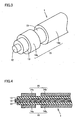
- Fig. 1 is a model diagram for illustrating the device structure of an electrode for a crusher and a crusher employing the electrode for a crusher according to a first embodiment of the present invention.
- Fig. 2 is a partially enlarged model diagram showing the forward end of the electrode for a crusher shown in Fig. 1.
- Fig. 3 is an enlarged schematic perspective view showing the forward end of the electrode for a crusher shown in Fig. 1.
- Fig. 4 is a schematic sectional view of the electrode for a crusher shown in Fig. 2.
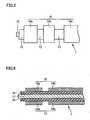
- Fig. 5 is a partially enlarged model diagram showing a first modification of the electrode for a crusher shown in Figs. 1 to 4.
- Fig. 6 is a schematic sectional view showing a second modification of the electrode for a crusher shown in Figs. 1 to 4.
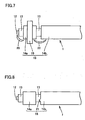
- Fig. 7 is a partially enlarged model diagram showing an electrode for a crusher according to a second embodiment of the present invention.
- Fig. 8 is a partially enlarged model diagram showing an electrode for a crusher according to a third embodiment of the present invention.
- Fig. 9 is a partially enlarged model diagram showing an electrode for a crusher according to a fourth embodiment of the present invention.
- Fig. 10 is a schematic sectional view of the electrode for a crusher shown in Fig. 9.
- Fig. 11 is a schematic sectional view showing a first modification of the electrode for a crusher shown in Figs. 9 and 10.
- Fig. 12 is a schematic sectional view showing a second modification of the electrode for a crusher shown in Figs. 9 and 10.
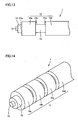
- Fig. 13 is a partially enlarged model diagram showing a third modification of the electrode for a crusher shown in Figs. 9 and 10.
- Fig. 14 is a schematic perspective view showing an electrode for a crusher according to a fifth embodiment of the present invention.
- Fig. 15 is a schematic sectional view of the electrode for a crusher shown in Fig. 14.
- Fig. 16 is a model diagram showing a modification of the electrode for a crusher according to the fifth embodiment shown in Figs. 14 and 15.
- Fig. 17 is a model diagram showing an electrode for a crusher employed for an experiment.
- Fig. 18 is a model diagram showing a state causing discharges in the experiment.
- Fig. 19 is a model diagram showing a conventional crusher.
- Fig. 20 is a model diagram showing the basic structure of the crusher shown in Fig. 19.
- Fig. 21 is a partially enlarged model diagram showing the forward end of the electrode shown in Fig. 20.
-
- Embodiments of the present invention are now described with reference to the drawings. In the following drawings, identical or corresponding parts are denoted by the same reference numerals, and redundant description is not repeated.
- An electrode for a crusher and a crusher according to a first embodiment of the present invention are described with reference to Figs. 1 to 4.
- Referring to Figs. 1 to 4, the crusher according to the present invention comprises a
coaxial electrode 1, apulse power source 6, apower source 9 and acoaxial cable 5. Thepulse power source 6 consists of a circuit including acapacitor 8, aswitch 7 and the like. Thepower source 9 is connected to thepulse power source 6. The circuit of thepulse power source 6 is grounded. Thecoaxial electrode 1 which is the electrode for a crusher is connected to thepulse power source 6 through thecoaxial cable 5. Thecoaxial electrode 1 comprises acenter electrode 12 serving as a central conductor extending along a central axis, aninsulator 13 serving as an insulating member arranged on the outer peripheral surface of thiscenter electrode 12, and aperipheral electrode 15 serving as a peripheral conductor arranged on the outer peripheral surface of thisinsulator 13. Thecoaxial electrode 1 is inserted in apreliminary hole 10 formed in a crushedobject 2 such as rock.Water 11 serving as en electrolyte is arranged in thepreliminary hole 10. An end of thecenter electrode 12 projects from theforward end 16 of thecoaxial electrode 1. Theperipheral electrode 15 includes aperipheral electrode part 14a serving as a first conductor located closer to theforward end 16 and aperipheral electrode part 14b serving as a second conductor arranged at a space from thisperipheral electrode part 14a in the extensional direction of the central axis. - When the
switch 7 of thepulse power source 6 is closed and charges stored in thecapacitor 8 are introduced into thecoaxial electrode 1, a first discharge is caused between the end of thecenter electrode 12 and theperipheral electrode part 14a, to form anarc 20. A discharge is caused also between theperipheral electrode part 14a and theperipheral electrode part 14b, to form anotherarc 20. - Thus, two
arcs 20 can be formed as described above when a current is supplied to thecoaxial electrode 1 serving as the electrode for a crusher and this current flows between thecenter electrode 12 and theperipheral electrode 15. In other words, discharges are caused at least on two portions in thecoaxial electrode 1 according to the present invention. while a discharge is caused only on one portion of an end in the conventional coaxial electrode. The number of portions causing discharges is so increased that discharge resistance can be increased beyond that in the prior art when setting the current to a constant value. As already described, the energy consumed by discharges is proportionate to the value obtained by multiplying the square of the value of the current supplied to thecoaxial electrode 1 by the discharge resistance, whereby the energy (i.e., the energy utilized for crushing) consumed by the discharges can be reliably increased beyond that in the prior art. Therefore, thecoaxial electrode 1 serving as the electrode for a crusher and a crusher capable of increasing crushability can be implemented. - A first modification of the electrode for a crusher shown in Figs. 1 to 4 is described with reference to Fig. 5.
- Referring to Fig. 5, a
coaxial electrode 1 which is the electrode for a crusher basically has a structure similar to that of the coaxial electrode shown in Figs. 1 to 4. In the coaxial electrode shown in Fig. 5, however, aperipheral electrode 15 includes threeperipheral electrode parts 14a to 14c. Theperipheral electrode parts 14a to 14c are arranged at spaces from each other respectively. In this case, an effect similar to that of the coaxial electrode shown in Figs. 1 to 4 can be attained while discharges can be caused on three portions, i.e., between an end of acenter electrode 12 and theperipheral electrode part 14a, between theperipheral electrode part 14a and theperipheral electrode part 14b and between theperipheral electrode part 14b and theperipheral electrode part 14c. Thus, discharge resistance can be further improved, whereby energy emitted by discharges can be further increased. Consequently, the ability of the crusher can be further improved. - The number of the peripheral electrode parts may be further increased for increasing the number of portions causing discharges. In this case, the ability of the crusher is further improved.
- A second modification of the electrode for a crusher shown in Figs. 1 to 4 is described with reference to Fig. 6.
- Referring to Fig. 6, a
coaxial electrode 1 which is the electrode for a crusher basically has a structure similar to that of the coaxial electrode shown in Figs. 1 to 4. However, a flexible strandedconductor 17 is employed as a center electrode. Further, aflexible insulator 18 of a rubber-based insulator or urethane is employed as an insulator. - When discharges are caused on a plurality of portions of the
coaxial electrode 1 in the central axis direction as in the present invention in an operation of crushing rock or the like, an impact may also transversely be applied to thecoaxial electrode 1. When employing thecoaxial electrode 1 having a certain degree of flexibility as described above in this case, the transverse impact can be absorbed by deformation of thecoaxial cable 1. Therefore, such an accident that thecoaxial electrode 1 is broken by the impact can be prevented. Thus, the life of thecoaxial electrode 1 can be increased. - An electrode for a crusher according to a second embodiment of the present invention is described with reference to Fig. 7.
- Referring to Fig. 7, a
coaxial electrode 1 serving as the electrode for a crusher basically has a structure similar to that of the coaxial electrode shown in Figs. 1 to 4, while a diametricalconvex portion 19 projecting in the outer peripheral direction and extending in the circumferential direction is formed on the central portion of aperipheral electrode part 14a. - In this case, it follows that a first discharge (arc 20) is caused between a portion of a
center electrode 12 located on an end of thecoaxial electrode 1 and theperipheral electrode part 14a serving as a first conductor while a second discharge (arc 20) is caused between theperipheral electrode part 14a and aperipheral electrode part 14b serving as a second conductor. In other words, twoarcs 20 are generated to hold theperipheral electrode part 14a therebetween. The diametricalconvex portion 19 is formed by relatively increasing the diameter of a region held between both ends in the extensional direction of a central axis in theperipheral electrode part 14a, so that the region causing the first discharge and the region causing the second discharge can be isolated from each other through this diametricalconvex portion 19. Consequently, thearcs 20 resulting from the first and second discharges can be prevented from integration. Thus, the number of discharge portions can be prevented from reduction, whereby discharge resistance can be prevented from reduction. Therefore, the ability of the crusher can be reliably improved. - An electrode for a crusher according to a third embodiment of the present invention is described with reference to Fig. 8.
- Referring to Fig. 8, a
coaxial electrode 1 serving as the electrode for a crusher basically has a structure similar to that of the coaxial electrode shown in Figs. 1 to 4, while a convex portion 21 serving as a projection projecting in a direction substantially parallel to the extensional direction of the central axis of acenter electrode 12 is formed on aperipheral electrode part 14b. - In this case, the convex portion 21 serving as the projection is formed on the
peripheral electrode part 14b so that the distance between aperipheral electrode part 14a and theperipheral electrode part 14b can be locally reduced when a current is supplied to thecoaxial electrode 1, whereby charges can be concentrated to this convex portion 21. Therefore, a discharge can be preferentially caused on the portion formed with this convex portion 21. Thus, the position of the region causing the discharge can be arbitrarily changed by changing the position of the convex portion 21. - The convex portion 21 may alternatively be formed on the
peripheral electrode part 14a, or may be formed on both of theperipheral electrode parts peripheral electrode parts - In addition, a convex portion may be formed on a portion of the
peripheral electrode part 14a closer to an end (the side exposing the center electrode 12) of thecoaxial electrode 1. In this case, the position causing a discharge can be changed between thecenter electrode 12 and theperipheral electrode part 14a by changing the position of this convex portion. Further, a similar effect can be attained also when forming the convex portion on an end of thecenter electrode 12. - An electrode for a crusher according to a third embodiment of the present invention is described with reference to Figs. 9 and 10.
- Referring to Figs. 9 and 10, a
coaxial electrode 1 serving as the electrode for a crusher basically has a structure similar to that of the coaxial electrode shown in Figs. 1 to 4, whileprojections peripheral electrode parts - The
projections holes peripheral electrode parts projections holes screw 23a inserted into the threadedhole 25a is inserted into and fixed to the threadedhole 24a of theperipheral electrode part 14a, thereby fixing theprojection 22a to theperipheral electrode part 14a. Ascrew 23b inserted into the threadedhole 25b is inserted into and fixed to the threadedhole 24b of theperipheral electrode part 14b, thereby fixing theprojection 22b to theperipheral electrode part 14b. - In this case, the shapes of the
peripheral electrode parts projections projections - A first modification of the electrode for a crusher shown in Figs. 9 and 10 is described with reference to Fig. 11. Fig. 11 corresponds to Fig. 10.
- Referring to Fig. 11, a
coaxial electrode 1 serving as the electrode for a crusher basically has a structure similar to that of thecoaxial electrode 1 shown in Figs. 9 and 10. However, ends 26a and 26b ofprojections peripheral electrode parts side walls peripheral electrode parts ends 26a and 26b of theprojections side walls peripheral electrode parts - According to this structure, the effect according to the coaxial electrode shown in Fig. 8 can also be simultaneously attained in addition to the effect according to the coaxial electrode shown in Figs. 9 and 10.
- A second modification of the electrode for a crusher shown in Figs. 9 and 10 is described with reference to Fig. 12. Fig. 12 corresponds to Fig. 10.
- Referring to Fig. 12, a
coaxial electrode 1 serving as the electrode for a crusher basically has a structure similar to that of thecoaxial electrode 1 shown in Figs. 9 and 10. However,projections peripheral electrode parts - A third modification of the electrode for a crusher shown in Figs. 9 and 10 is described with reference to Fig. 13. Fig. 13 corresponds to Fig. 9.
- Referring to Fig. 13, a
coaxial electrode 1 serving as the electrode for a crusher basically has a structure similar to that of thecoaxial electrode 1 shown in Figs. 9 and 10. In thecoaxial electrode 1 shown in Fig. 13, however,convex portions 21a to 21c are formed on both ends of aperipheral electrode part 14a and an end of aperipheral electrode part 14b to project in a direction substantially parallel to the extensional direction of the central axis of acenter electrode 12. Theconvex portions 21a to 21c are made of materials similar to those forming theperipheral electrode parts convex portions convex part 21a in the circumferential direction of the central axis of thecenter electrode 12. When a current is supplied to the coaxial electrode, therefore, a discharge (first discharge) between thecenter electrode 12 and theperipheral electrode part 14a is caused on the region between thecenter electrode 12 and theconvex portion 21a. On the other hand, a discharge (second discharge) between theperipheral electrode part 14a and theperipheral electrode part 14b is caused on the region between theconvex portions - Thus, an arc resulting from the first discharge and an arc resulting from the second discharge can be prevented from connection. Therefore, energy utilized for crushing can be prevented from reduction resulting from connection of the arcs in the first and second discharges.
- An electrode for a crusher according to a fifth embodiment of the present invention is described with reference to Figs. 14 and 15.
- Referring to Figs. 14 and 15, a
coaxial electrode 1 which is the electrode for a crusher basically has a structure similar to that of the coaxial electrode shown in Figs. 1 to 4. In thecoaxial electrode 1 shown in Figs. 14 and 15, however, aperipheral electrode 15 includes fourperipheral electrode parts 14a to 14d. Theperipheral electrode parts 14a to 14d are arranged at spaces from each other respectively. It is assumed that L1 to L3 represent the widths of theperipheral electrodes 14a to 14c in a central axis direction respectively. It is also assumed that the space between theperipheral electrodes peripheral electrodes peripheral electrodes center electrode 12 and theperipheral electrode part 14a, between theperipheral electrode part 14a and theperipheral electrode part 14b, between theperipheral electrode part 14b and theperipheral electrode part 14c and between theperipheral electrode part 14c and theperipheral electrode part 14d. Therefore, discharge resistance can be further improved, whereby energy emitted by discharges can be further increased. Consequently, the ability of the crusher can be further improved. - A modification of the electrode for a crusher according to the fifth embodiment is described with reference to Fig. 16.
- Referring to Fig. 16, a
coaxial electrode 1 serving as the electrode for a crusher basically has a structure similar to that of thecoaxial electrode 1 shown in Figs. 14 and 15. In thecoaxial electrode 1 shown in Fig. 16, however,convex portions 21a to 21d are formed on the respective ones ofperipheral electrode parts 14a to 14c. Theconvex portions 21a to 21d are formed to project in a direction substantially parallel to the extensional direction of the central axis of acenter electrode 12. Theconvex portions 21a to 21d are formed on positions different from each other in the circumferential direction of the central axis of thecenter electrode 12. - A discharge (first discharge) between the forward end of the
center electrode 12 and theperipheral electrode part 14a is caused on the region between theconvex portion 21a and thecenter electrode 12. A discharge (second discharge) between theperipheral electrode part 14a and theperipheral electrode part 14b is caused on the region between theconvex portion 21b and theperipheral electrode 14b. A discharge (third discharge) between theperipheral electrode part 14b and theperipheral electrode part 14c is caused on the region between theconvex portion 21c and theperipheral electrode 14c. A discharge (fourth discharge) between theperipheral electrode part 14c and aperipheral electrode part 14d is caused on the region between theconvex portion 21d and theperipheral electrode 14d. - Thus, the
convex portions 21a to 21d serving as projections are so formed that charges can be concentrated to theconvex portions 21a to 21d, whereby the first to fourth discharges can be caused in the vicinity of the portions formed with theconvex portions 21a to 21d respectively. Thus, the positions causing the first to fourth discharges can be arbitrarily changed by changing the positions of theconvex portions 21a to 21d. - When the
convex portions 21a to 21d are arranged as shown in Fig. 16, it follows that the first to fourth discharges caused in the coaxial electrode are formed on positions different from each other in the circumferential direction of the central axis of thecenter electrode 12. Therefore, arcs of adjacent discharges can be reliably prevented from connection. - While the
convex portions 21a to 21d are formed to project in the direction substantially parallel to the extensional direction of the central axis of thecenter electrode 12 in Fig. 16, theconvex portions 21a to 21d may alternatively be formed to project in the radial direction of the central axis as shown in Figs. 9 to 12. Also in this case, an effect similar to that of the coaxial electrode shown in Fig. 16 can be attained. - The widths (the lengths in the extensional direction of the central axis of the center electrode 12) of the
peripheral electrodes 14a to 14d in the first to fifth embodiments of the present invention are preferably at least 10 mm. In this case, the arcs formed following the discharges can grow to sufficient sizes with no restriction by the widths of theperipheral electrodes 14a to 14d. Therefore, the energy utilized for crushing can be increased. - The widths of the
peripheral electrodes 14a to 14d in the first to fifth embodiments of the present invention may be at least 20 mm. Thus, also when two adjacent discharges are caused on positions close to each other in the circumferential direction of the central axis of thecenter electrode 12, arcs resulting from the two discharges can be reliably prevented from connection. - In order to confirm the effects of the present invention, the inventor has made a discharge experiment with the electrode for a crusher according to the present invention. This experiment is described with reference to Figs. 17 and 18.
- Referring to Fig. 17, a
coaxial electrode 1 serving as the electrode for a crusher prepared by the inventor basically has a structure similar to that of the electrode for a crusher according to the fifth embodiment of the present invention. In other words, thecoaxial electrode 1 comprises acenter electrode 12, aninsulator 13 arranged on the outer peripheral surface of thiscenter electrode 12 andperipheral electrode parts 14a to 14d arranged on the outer peripheral surface of thisinsulator 13. Thecenter electrode 12 extends along a central axis, and consists of copper. The diameter of thecenter electrode 12 is 20 mm. Theinsulator 13 consists of FRP (fiber reinforced plastics), and the thickness thereof is 10 mm. Theperipheral electrode parts 14a to 14d forming aperipheral electrode 15 consist of copper, and the thickness thereof is 5 mm. Therefore, the outer diameter of thecoaxial electrode 1 is 50 mm. The width L of theperipheral electrode parts 14a to 14c is 27 mm, and the distance W between theperipheral electrodes 14a to 14d was set to 10 mm. A capacitor having electrostatic capacitance of 2 mF was charged up to 15 kV, and thereafter this capacitor and the aforementionedcoaxial electrode 1 were connected with each other through a cable having circuit impedance of 3 µH, thereby causing discharges in thecoaxial electrode 1. - As shown in Fig. 18, arcs 20a having relatively small sizes are caused between the
peripheral electrodes 14a to 14d immediately after starting the discharges. The sizes of the arcs are increased with time, to finally form arcs 20b having relatively large sizes. In the sufficiently enlarged (grown) arcs 20b, it was observed that ends of thearcs 20b in the direction along the central axis of thecenter electrode 12 inwardly extended by a length LA from the ends of theperipheral electrode parts 14a to 14d. The value of the length LA was about 10 mm. - Also when the charging voltage for the capacitor was varied in the range of 6 to 15 kV, the situation of formation of the arcs remained substantially unchanged and the value of the length LA was substantially 10 mm. Also when the distance W between the
peripheral electrodes 14a to 14d was varied, this length LA remained substantially unchanged. - Thus, it is understood that sufficiently grown
large arcs 20b can be formed in discharges when the width L of theperipheral electrodes 14a to 14d is at least 10 mm (when the width L of theperipheral electrodes 14a to 14d is set to less than 10 mm, the arcs cannot be sufficiently grown and hence it is conceivable that the amount of energy utilized for crushing is consequently reduced. Depending on the positions of adjacent arcs, there is a possibility of such a phenomenon that the adjacent arcs (for example, the arc generated between theperipheral electrodes peripheral electrodes - In the
coaxial electrode 1,convex portions 21a to 21d may be formed on theperipheral electrodes 14a to 14d on positions different from each other in the circumferential direction of the central axis of thecenter electrode 12, as shown in Fig. 16. In this case, arcs can be generated on different positions in the circumferential direction of the central axis of thecenter electrode 12. Also when the width L of theperipheral electrodes 14a to 14c is about 10 mm, therefore, theadjacent arcs 20b can be reliably prevented from connection. - When the width L of the
peripheral electrodes 14a to 14d is set to a length of at least 20 mm as in thecoaxial electrode 1 employed for the experiment, thearcs 20b can be reliably prevented from connection even if theadjacent arcs 20b are formed on positions close to each other in the circumferential direction of the central axis of thecenter electrode 12. - The embodiments and Example disclosed this time must be considered as illustrative and not restrictive in al points. The scope of the present invention is shown not by the aforementioned embodiments and Example but by the scope of claim for patent, and it is intended that all modifications in the meaning and range equivalent to the scope of claim for patent are included.
- According to the present invention, as hereinabove described, discharges can be caused on a plurality of positions with a single electrode for a crusher, whereby energy utilized for crushing can be increased.
- As hereinabove described, the electrode for a crusher according to the present invention can be applied to crushing of rock or bedrock, crushing of an artificial structure of concrete, or the like.
Claims (15)
- An electrode (1) for a crusher, comprising:said peripheral conductor (15) includes:a central conductor (12, 17) extending along a central axis and having an outer peripheral surface;an insulating member (13, 18) arranged on the outer peripheral surface of said central conductor (12, 17); anda peripheral conductor (15) arranged to enclose said insulating member (13, 18), whereina first conductor (14a), anda second conductor (14b) arranged at a space from said first conductor (14a) in the extensional direction of said central axis.
- The electrode (1) for a crusher according to claim 1, wherein
said central conductor (12, 17) includes an end causing a discharge,
said first conductor (14a) is arranged closer to said end in the extensional direction of said central axis and includes both ends in the extensional direction of said central axis and a region held between said both ends,
both ends of said first conductor have portions having relatively small diameters, and
the region held between said both ends of said first conductor includes a portion (19) having a relatively large diameter. - The electrode (1) for a crusher according to claim 1, wherein
a projection (21, 21a to 21c, 22a, 22b, 28a, 28b) is formed on at least either one of said first and second conductors (14a, 14b). - The electrode (1) for a crusher according to claim 3, wherein
said projection (21, 21a to 21c, 22a, 22b) projects in a direction substantially parallel to the extensional direction of said central axis. - The electrode (1) for a crusher according to claim 3, wherein
said projection (22a, 22b, 28a, 28b) projects in the radial direction of said central axis. - The electrode (1) for a crusher according to claim 3, wherein
said projection (21a to 21c) includes:a first projection (21a) formed on either one of said first and second conductors (14a, 14b), anda second projection (21b, 21c) formed on a position different from the position of said first projection (21a) in the circumferential direction of said central axis on at least either one of said first and second conductors (14a, 14b). - The electrode (1) for a crusher according to claim 1, wherein
the length of at least either one of said first and second conductors (14a, 14b) is at least 10 mm in the extensional direction of said central axis. - The electrode (1) for a crusher according to claim 1, wherein
said peripheral conductor (15) includes at least one additional conductor (14c, 14d) arranged at a space from said second conductor (14b) in the extensional direction of said central axis. - The electrode (1) for a crusher according to claim 8, wherein
a projection (21a to 21d) is formed on at least one conductor selected from a group consisting of said first conductor (14a), said second conductor (14b) and said additional conductor (14c, 14d). - The electrode (1) for a crusher according to claim 9, wherein
said projection (21a to 21d) projects in a direction substantially parallel to the extensional direction of said central axis. - The electrode (11) for a crusher according to claim 9, wherein
said projection projects in the radial direction of said central axis. - The electrode (1) for a crusher according to claim 9, wherein
said projection (21a to 21d) includes:a first projection (21a) formed on one conductor selected from the group consisting of said first conductor (14a), the second conductor (14b) and the additional conductor (14c, 14d), anda second projection (21b to 21d) formed on a position different from the position of said first projection (21a) in the circumferential direction of said central axis in at least one conductor selected from the group consisting of said first conductor (14a), the second conductor (14b) and the additional conductor (14c, 14d). - The electrode (1) for a crusher according to claim 8, wherein
the length of at least one conductor selected from a group consisting of said first conductor (14a), the second conductor (14b) and the additional conductor (14c, 14d) is at least 10 mm in the extensional direction of said central axis. - The electrode (1) for a crusher according to claim 1, wherein
said central conductor (17) includes a stranded conductor, and
said insulating member (18) contains a flexible material. - A crusher comprising the electrode (1) for a crusher according to claim 1.
Applications Claiming Priority (3)
| Application Number | Priority Date | Filing Date | Title |
|---|---|---|---|
| JP2001108388 | 2001-04-06 | ||
| JP2001108388A JP3563363B2 (en) | 2000-12-08 | 2001-04-06 | Electrode for crusher and crusher |
| PCT/JP2002/003387 WO2002083312A1 (en) | 2001-04-06 | 2002-04-04 | Crushing apparatus electrode and crushing apparatus |
Publications (2)
| Publication Number | Publication Date |
|---|---|
| EP1375004A1 true EP1375004A1 (en) | 2004-01-02 |
| EP1375004A4 EP1375004A4 (en) | 2005-03-16 |
Family
ID=18960536
Family Applications (1)
| Application Number | Title | Priority Date | Filing Date |
|---|---|---|---|
| EP02714461A Withdrawn EP1375004A4 (en) | 2001-04-06 | 2002-04-04 | ELECTRODE FOR MILLING APPARATUS AND MILLING APPARATUS |
Country Status (6)
| Country | Link |
|---|---|
| US (1) | US6935702B2 (en) |
| EP (1) | EP1375004A4 (en) |
| KR (1) | KR100512812B1 (en) |
| CN (1) | CN1461239A (en) |
| CA (1) | CA2416034A1 (en) |
| WO (1) | WO2002083312A1 (en) |
Cited By (2)
| Publication number | Priority date | Publication date | Assignee | Title |
|---|---|---|---|---|
| WO2010092136A1 (en) | 2009-02-13 | 2010-08-19 | Camille Compagnie D'assistance Miniere Et Industrielle | Method and system for reusing materials and/or products by pulsed power |
| WO2011023443A1 (en) | 2009-08-26 | 2011-03-03 | Camille Compagnie D'assistance Miniere Et Industrielle | Method and system for reusing material and/or products by pulsed power |
Families Citing this family (28)
| Publication number | Priority date | Publication date | Assignee | Title |
|---|---|---|---|---|
| US8172006B2 (en) | 2004-08-20 | 2012-05-08 | Sdg, Llc | Pulsed electric rock drilling apparatus with non-rotating bit |
| US9190190B1 (en) | 2004-08-20 | 2015-11-17 | Sdg, Llc | Method of providing a high permittivity fluid |
| US8789772B2 (en) | 2004-08-20 | 2014-07-29 | Sdg, Llc | Virtual electrode mineral particle disintegrator |
| US7416032B2 (en) | 2004-08-20 | 2008-08-26 | Tetra Corporation | Pulsed electric rock drilling apparatus |
| US10060195B2 (en) | 2006-06-29 | 2018-08-28 | Sdg Llc | Repetitive pulsed electric discharge apparatuses and methods of use |
| SK50872007A3 (en) | 2007-06-29 | 2009-01-07 | Ivan Kočiš | Device for excavation boreholes in geological formation and method of energy and material transport in this boreholes |
| SK288264B6 (en) | 2009-02-05 | 2015-05-05 | Ga Drilling, A. S. | Device to carry out the drillings and method of carry out the drillings |
| US20100237850A1 (en) * | 2009-03-19 | 2010-09-23 | Ahmed Abdullah Salem Al-Ghamdi | Device and method for testing food quality |
| SK50622009A3 (en) | 2009-09-24 | 2011-05-06 | Ivan Kočiš | Method for material dislodging and device there of |
| US8628146B2 (en) * | 2010-03-17 | 2014-01-14 | Auburn University | Method of and apparatus for plasma blasting |
| CA2860775A1 (en) | 2011-01-07 | 2012-07-12 | Sdg Llc | Apparatus and method for supplying electrical power to an electrocrushing drill |
| US10407995B2 (en) | 2012-07-05 | 2019-09-10 | Sdg Llc | Repetitive pulsed electric discharge drills including downhole formation evaluation |
| US10113364B2 (en) | 2013-09-23 | 2018-10-30 | Sdg Llc | Method and apparatus for isolating and switching lower voltage pulses from high voltage pulses in electrocrushing and electrohydraulic drills |
| CN103753701B (en) * | 2013-12-30 | 2015-12-09 | 华中科技大学 | A kind of Pulse discharge concrete recovery system |
| US10577767B2 (en) * | 2018-02-20 | 2020-03-03 | Petram Technologies, Inc. | In-situ piling and anchor shaping using plasma blasting |
| US11268796B2 (en) * | 2018-02-20 | 2022-03-08 | Petram Technologies, Inc | Apparatus for plasma blasting |
| US10866076B2 (en) * | 2018-02-20 | 2020-12-15 | Petram Technologies, Inc. | Apparatus for plasma blasting |
| US10844702B2 (en) * | 2018-03-20 | 2020-11-24 | Petram Technologies, Inc. | Precision utility mapping and excavating using plasma blasting |
| CN108871130B (en) * | 2018-06-29 | 2024-05-17 | 中国地质大学(北京) | Plasma blasting rock mechanical device capable of realizing hole wall sealing |
| CN110215985B (en) * | 2019-07-05 | 2021-06-01 | 东北大学 | High-voltage electric pulse device for ore crushing pretreatment |
| CN111910952A (en) * | 2020-06-11 | 2020-11-10 | 哈尔滨理工大学 | Environment-friendly concrete structure crushing device and crushing method adopting high-voltage pulse technology |
| US12312956B2 (en) | 2020-09-03 | 2025-05-27 | Petram Technologies, Inc. | Robust plasma blast probe tip |
| US11536124B2 (en) * | 2020-09-03 | 2022-12-27 | Petram Technologies, Inc. | Sliced and elliptical head probe for plasma blast applications |
| CN112483086B (en) * | 2020-10-30 | 2022-02-08 | 北京科技大学 | System for causing metal ore bed to be cracked by instant electric pulse and using method |
| CN114869399B (en) * | 2021-02-05 | 2025-03-07 | 沛嘉医疗科技(苏州)有限公司 | Electrode assembly and shock wave device using the same |
| US12611219B2 (en) | 2021-02-05 | 2026-04-28 | Peijia Medical (Suzhou) Co., Ltd. | Electrode assembly and shock wave apparatus using the electrode assembly |
| US11203400B1 (en) | 2021-06-17 | 2021-12-21 | General Technologies Corp. | Support system having shaped pile-anchor foundations and a method of forming same |
| CN115337076A (en) * | 2022-07-15 | 2022-11-15 | 深圳英美达医疗技术有限公司 | Shock wave balloon catheter |
Family Cites Families (8)
| Publication number | Priority date | Publication date | Assignee | Title |
|---|---|---|---|---|
| US3713166A (en) * | 1970-12-18 | 1973-01-23 | Ball Brothers Res Corp | Flush mounted antenna and receiver tank circuit assembly |
| US4115783A (en) * | 1977-06-14 | 1978-09-19 | The United States Of America As Represented By The Secretary Of The Army | Broadband hybrid monopole antenna |
| US4653697A (en) * | 1985-05-03 | 1987-03-31 | Ceee Corporation | Method and apparatus for fragmenting a substance by the discharge of pulsed electrical energy |
| JPS63221857A (en) | 1987-03-10 | 1988-09-14 | 桜井 誠也 | Crusher |
| ZA91612B (en) | 1990-04-20 | 1991-10-30 | Noranda Inc | Plasma blasting method |
| US5425570A (en) * | 1994-01-21 | 1995-06-20 | Maxwell Laboratories, Inc. | Method and apparatus for plasma blasting |
| KR0184541B1 (en) | 1995-10-30 | 1999-04-01 | 박주탁 | Gold Schmidt Rock Device |
| KR100308081B1 (en) | 1999-03-02 | 2001-09-24 | 정기형 | Electro-power impactor cell for plasma blasting |
-
2002
- 2002-04-04 CN CN02801114A patent/CN1461239A/en active Pending
- 2002-04-04 US US10/333,076 patent/US6935702B2/en not_active Expired - Fee Related
- 2002-04-04 EP EP02714461A patent/EP1375004A4/en not_active Withdrawn
- 2002-04-04 KR KR10-2002-7016565A patent/KR100512812B1/en not_active Expired - Fee Related
- 2002-04-04 WO PCT/JP2002/003387 patent/WO2002083312A1/en not_active Ceased
- 2002-04-04 CA CA002416034A patent/CA2416034A1/en not_active Abandoned
Non-Patent Citations (2)
| Title |
|---|
| No further relevant documents disclosed * |
| See also references of WO02083312A1 * |
Cited By (3)
| Publication number | Priority date | Publication date | Assignee | Title |
|---|---|---|---|---|
| WO2010092136A1 (en) | 2009-02-13 | 2010-08-19 | Camille Compagnie D'assistance Miniere Et Industrielle | Method and system for reusing materials and/or products by pulsed power |
| WO2010092134A1 (en) | 2009-02-13 | 2010-08-19 | Camille Compagnie D'assistance Miniere Et Industrielle | Method and system for reusing materials and/or products by pulsed power |
| WO2011023443A1 (en) | 2009-08-26 | 2011-03-03 | Camille Compagnie D'assistance Miniere Et Industrielle | Method and system for reusing material and/or products by pulsed power |
Also Published As
| Publication number | Publication date |
|---|---|
| KR100512812B1 (en) | 2005-09-13 |
| US6935702B2 (en) | 2005-08-30 |
| WO2002083312A1 (en) | 2002-10-24 |
| US20040026548A1 (en) | 2004-02-12 |
| KR20030007874A (en) | 2003-01-23 |
| CN1461239A (en) | 2003-12-10 |
| CA2416034A1 (en) | 2003-01-13 |
| EP1375004A4 (en) | 2005-03-16 |
Similar Documents
| Publication | Publication Date | Title |
|---|---|---|
| US6935702B2 (en) | Crushing apparatus electrode and crushing apparatus | |
| US6457778B1 (en) | Electro-power impact cell for plasma blasting | |
| US6283555B1 (en) | Plasma blasting with coaxial electrodes | |
| US6627820B2 (en) | Organic composite insulator and method of producing the same | |
| JP3563363B2 (en) | Electrode for crusher and crusher | |
| US7842907B2 (en) | Microwave generator | |
| RU2388124C2 (en) | High-voltage switch and its application in microwave generator | |
| EP1065502B1 (en) | Method for analyzing the breakdown characteristics of a gaseous dielectric in a highly non-uniform field | |
| JP4783936B2 (en) | Crusher electrode and crusher | |
| KR19980018739A (en) | THE METHOD AND DEVICE FOR DESTRUCTION BY PULSE ELECTRIC ENERGY DISCHARGE, AND THE METHOD AND DEVICE FOR HIGH VOLTAGE PULSE GENERATION | |
| JP4098596B2 (en) | Crusher electrode, crusher and crushing method | |
| JP4783937B2 (en) | Method for manufacturing electrode for crushing device | |
| JP3563369B2 (en) | Crushing method | |
| JP3898931B2 (en) | Crusher electrode and crusher | |
| KR970065961A (en) | Electrodes for plasma waves | |
| JP2002361112A (en) | Electrode for crushing device, crushing device and crushing method | |
| KR100707751B1 (en) | Electrode for High Power System | |
| CN212847768U (en) | Pulse high-voltage switch wire harness | |
| JP3103017B2 (en) | Destruction equipment for destroyed objects | |
| KR100698226B1 (en) | Electrode for High Power System | |
| JPH11260589A (en) | Static eliminator | |
| RU893113C (en) | Controlled gas-filled discharger | |
| JP2000179277A (en) | Electrolysis electrode | |
| EP0405816A2 (en) | A discharge tube arrangement | |
| KR20010009453A (en) | High power helical arc switch |
Legal Events
| Date | Code | Title | Description |
|---|---|---|---|
| PUAI | Public reference made under article 153(3) epc to a published international application that has entered the european phase |
Free format text: ORIGINAL CODE: 0009012 |
|
| 17P | Request for examination filed |
Effective date: 20021223 |
|
| AK | Designated contracting states |
Kind code of ref document: A1 Designated state(s): AT BE CH CY DE DK ES FI FR GB GR IE IT LI LU MC NL PT SE TR |
|
| A4 | Supplementary search report drawn up and despatched |
Effective date: 20050201 |
|
| RIC1 | Information provided on ipc code assigned before grant |
Ipc: 7F 42D 3/04 B Ipc: 7E 21C 37/18 B Ipc: 7B 02C 19/18 B Ipc: 7B 02C 19/00 A |
|
| STAA | Information on the status of an ep patent application or granted ep patent |
Free format text: STATUS: THE APPLICATION IS DEEMED TO BE WITHDRAWN |
|
| 18D | Application deemed to be withdrawn |
Effective date: 20040703 |