EP1374962A1 - Perfectionnement à un dispositif pour séparer un mélange comprenant au moins une phase gazeuse et une phase liquide, ledit dispositif étant intégré dans une enceinte - Google Patents
Perfectionnement à un dispositif pour séparer un mélange comprenant au moins une phase gazeuse et une phase liquide, ledit dispositif étant intégré dans une enceinte Download PDFInfo
- Publication number
- EP1374962A1 EP1374962A1 EP02291587A EP02291587A EP1374962A1 EP 1374962 A1 EP1374962 A1 EP 1374962A1 EP 02291587 A EP02291587 A EP 02291587A EP 02291587 A EP02291587 A EP 02291587A EP 1374962 A1 EP1374962 A1 EP 1374962A1
- Authority
- EP
- European Patent Office
- Prior art keywords
- fraction
- liquid
- separator
- pipe
- enclosure
- Prior art date
- Legal status (The legal status is an assumption and is not a legal conclusion. Google has not performed a legal analysis and makes no representation as to the accuracy of the status listed.)
- Granted
Links
- 239000007791 liquid phase Substances 0.000 title claims abstract description 22
- 239000000203 mixture Substances 0.000 title claims abstract description 21
- 238000000926 separation method Methods 0.000 title claims description 27
- 239000007788 liquid Substances 0.000 claims abstract description 100
- 239000007789 gas Substances 0.000 claims abstract description 57
- 210000003918 fraction a Anatomy 0.000 claims abstract description 19
- 210000002196 fr. b Anatomy 0.000 claims abstract description 13
- 239000007792 gaseous phase Substances 0.000 claims abstract description 9
- 230000005484 gravity Effects 0.000 claims abstract description 3
- 239000002245 particle Substances 0.000 claims description 28
- 238000004064 recycling Methods 0.000 claims description 28
- 239000007787 solid Substances 0.000 claims description 22
- 230000005587 bubbling Effects 0.000 claims description 13
- 229930195733 hydrocarbon Natural products 0.000 claims description 13
- 150000002430 hydrocarbons Chemical class 0.000 claims description 13
- 239000003054 catalyst Substances 0.000 claims description 11
- 239000007790 solid phase Substances 0.000 claims description 7
- 239000004215 Carbon black (E152) Substances 0.000 claims description 6
- 239000001257 hydrogen Substances 0.000 claims description 6
- 229910052739 hydrogen Inorganic materials 0.000 claims description 6
- UFHFLCQGNIYNRP-UHFFFAOYSA-N Hydrogen Chemical compound [H][H] UFHFLCQGNIYNRP-UHFFFAOYSA-N 0.000 claims description 4
- 230000033001 locomotion Effects 0.000 claims description 4
- 238000000605 extraction Methods 0.000 abstract 2
- 238000006243 chemical reaction Methods 0.000 description 14
- 239000012071 phase Substances 0.000 description 14
- 230000003197 catalytic effect Effects 0.000 description 10
- 239000012530 fluid Substances 0.000 description 9
- 238000000034 method Methods 0.000 description 9
- 238000009835 boiling Methods 0.000 description 7
- 239000012263 liquid product Substances 0.000 description 4
- 238000011144 upstream manufacturing Methods 0.000 description 4
- 238000007599 discharging Methods 0.000 description 3
- 238000009434 installation Methods 0.000 description 3
- 238000005259 measurement Methods 0.000 description 3
- JTJMJGYZQZDUJJ-UHFFFAOYSA-N phencyclidine Chemical class C1CCCCN1C1(C=2C=CC=CC=2)CCCCC1 JTJMJGYZQZDUJJ-UHFFFAOYSA-N 0.000 description 3
- 238000010079 rubber tapping Methods 0.000 description 3
- 239000002002 slurry Substances 0.000 description 3
- 239000003245 coal Substances 0.000 description 2
- 239000010779 crude oil Substances 0.000 description 2
- 150000002431 hydrogen Chemical class 0.000 description 2
- 238000002156 mixing Methods 0.000 description 2
- 239000000725 suspension Substances 0.000 description 2
- 238000013019 agitation Methods 0.000 description 1
- 230000015572 biosynthetic process Effects 0.000 description 1
- 230000000903 blocking effect Effects 0.000 description 1
- 238000004581 coalescence Methods 0.000 description 1
- 238000010908 decantation Methods 0.000 description 1
- 230000006866 deterioration Effects 0.000 description 1
- 230000001627 detrimental effect Effects 0.000 description 1
- 238000004821 distillation Methods 0.000 description 1
- 230000000694 effects Effects 0.000 description 1
- 238000011049 filling Methods 0.000 description 1
- 238000005194 fractionation Methods 0.000 description 1
- -1 hydrodesulfurization Chemical class 0.000 description 1
- 230000001939 inductive effect Effects 0.000 description 1
- 230000003993 interaction Effects 0.000 description 1
- 239000000463 material Substances 0.000 description 1
- 238000012856 packing Methods 0.000 description 1
- 238000005192 partition Methods 0.000 description 1
- 239000003208 petroleum Substances 0.000 description 1
- 238000004525 petroleum distillation Methods 0.000 description 1
- 230000001737 promoting effect Effects 0.000 description 1
- 230000000630 rising effect Effects 0.000 description 1
- 239000000126 substance Substances 0.000 description 1
- 238000005292 vacuum distillation Methods 0.000 description 1
Images


Classifications
-
- B—PERFORMING OPERATIONS; TRANSPORTING
- B01—PHYSICAL OR CHEMICAL PROCESSES OR APPARATUS IN GENERAL
- B01D—SEPARATION
- B01D19/00—Degasification of liquids
- B01D19/0042—Degasification of liquids modifying the liquid flow
- B01D19/0052—Degasification of liquids modifying the liquid flow in rotating vessels, vessels containing movable parts or in which centrifugal movement is caused
- B01D19/0057—Degasification of liquids modifying the liquid flow in rotating vessels, vessels containing movable parts or in which centrifugal movement is caused the centrifugal movement being caused by a vortex, e.g. using a cyclone, or by a tangential inlet
-
- B—PERFORMING OPERATIONS; TRANSPORTING
- B01—PHYSICAL OR CHEMICAL PROCESSES OR APPARATUS IN GENERAL
- B01D—SEPARATION
- B01D53/00—Separation of gases or vapours; Recovering vapours of volatile solvents from gases; Chemical or biological purification of waste gases, e.g. engine exhaust gases, smoke, fumes, flue gases, aerosols
- B01D53/14—Separation of gases or vapours; Recovering vapours of volatile solvents from gases; Chemical or biological purification of waste gases, e.g. engine exhaust gases, smoke, fumes, flue gases, aerosols by absorption
Definitions
- the present invention relates to a device bringing into play in the same enclosure a solid phase and liquid and gas phases.
- the invention generally finds its application in the fields of conversion and / or treatment of distillates or residues from petroleum distillation. More precisely, said invention allows to improve, within a reaction vessel, the separation of a mixture comprising a gaseous fraction and a liquid fraction optionally comprising particles solids, said mixture coming from a zone of contacting a liquid phase, a gas phase and solid particles.
- said solid particles may for example be dispersed in said liquid phase within a suspension in a lower zone of the enclosure (slurry reactor).
- said phase solid may be included in a bubbling bed of solid particles.
- the present invention finds for example its application in the conversion of a charge introduced into said enclosure in the form liquid and containing hydrocarbons, said conversion being effected by bringing into contact with a gas phase, comprising for example hydrogen (hydroconversion) and with a solid phase which most often exhibits catalytic activity.
- a gas phase comprising for example hydrogen (hydroconversion) and with a solid phase which most often exhibits catalytic activity.
- Said charge can be, without departing from the scope of the invention, an atmospheric residue obtained by direct distillation of crude oil, a distillate obtained by vacuum distillation of a atmospheric residue of a crude oil or a liquid hydrocarbon charge from a coal.
- the invention can also, for example, be applied to processes for hydrotreating feedstocks hydrocarbons such as hydrodesulfurization, hydrodenitrogenation processes, hydrodemetallization or hydrodearomatization of various petroleum fractions.
- the present device is applicable to any process requiring contacting a gas phase and a liquid phase with a bed of solid particles
- the invention will be the following description, without limitation, in the particular case of the hydroconversion of a charge of hydrocarbons in a bubbling bed of solid catalytic particles.
- the bubbling bed process used for the hydroconversion of heavy fractions of hydrocarbons or a liquid hydrocarbon feedstock from a coal consists generally to bring into contact, in upward co-current flow, a charge hydrocarbon in liquid phase and a gas phase in a reactor containing a solid phase usually comprising a hydroconversion catalyst.
- the area reaction preferably comprises at least one means for withdrawing the particles solids located near the bottom of the reactor and at least one means for adding said particles containing a catalyst near the top of said reactor.
- Said area most often includes at least one circuit allowing the recycling of the liquid phase, located inside or outside the reaction zone, said recycling being intended, according to a technique known to those skilled in the art, to maintain a level sufficient bed expansion to ensure the proper functioning of the reaction zone in three-phase regime (gas / solid / liquid).
- US patent Re 25,770 describes for example such a process.
- a mixture of hydrocarbons liquids and hydrogen is injected through a catalyst bed in such a way that the bed is expanding.
- the level of catalyst is controlled by recycling the liquid, said level of catalyst remaining below that of the liquid.
- Gas and liquid hydrogenated cross an interface delimiting an area containing the major part of solid particles from the catalyst bed and are found in a practically free area of said particles.
- said fluids are then divided into two fractions: a fraction containing most of the liquid is recycled to the boiling pump and another part is withdrawn from the reactor with gas.
- said gas / liquid separation is not complete and a quantity substantial gas is entrained with the liquid towards the boiling pump via the conduit of recycles. This entrainment of gas is harmful because it causes a cavitation phenomenon of the pump as well as a deterioration of the catalyst level control which can go up to the total loss of bed expansion.
- US patent 4,221,653 describes equipment internal to the reactor and consisting of a cup preferably conical in shape with chimneys arranged on two circles concentric. Depending on the position of the conduits, the composition of the fluid passing through it varies. A distinction is made between gas-rich and liquid-rich conduits. Rich conduits in gas are those located on the outskirts. Their entry is located on the surface of the cup and their outlet is placed far enough from the outlets of the liquid-rich tubes and the conduit to recycle to minimize gas-liquid interactions. The entry of liquid-rich conduits is located below the surface of the cup. After crossing the cup recycles, most of the liquid is recycled to the boiling pump and the rest is withdrawn from the reactor with the gas. A fraction of gas, estimated at less than 8% in volume, however is entrained with the recycled liquid.
- US Patent 4,886,644 proposes to improve the previous device by adding inserts helical which communicate to the fluid a tangential speed. It is also proposed adding cyclones over the conduits to further improve the efficiency of the separation of the gaseous fraction and the liquid fraction.
- Patent 4,810,359 describes a device where the separation of the gaseous and liquid fractions is operated using a cyclone placed at the head of the reactor.
- the cyclone is connected to the recycles which brings the liquid back to a pump. Thanks to this device, a major part of the gaseous fraction is removed from the recycled liquid but a substantial part of the liquid is entrained in the gas of the upper part of said cyclone.
- Patent application EP 732,389 proposes using two reactors in series by including a gas-liquid separator between said two reactors. Part of the fluid from the first reactor is recycled to said first reactor so as to maintain the boiling of the catalyst while the other part is sent to said gas / liquid separator. The essentially liquid fraction resulting from this separation then feeds at least partially a second reactor arranged in series. For economic reasons, the separator placed after the reactor is much smaller than the reactor and control of the liquid level in the external separator is therefore very difficult in this type of process.
- said recycling cup sometimes commonly called “recycle” is conical shape and placed substantially in the center of said enclosure.
- said second discharge pipe is connected to recycling means in the enclosure of at least part of fraction A.
- the installation further comprises a second separation element or secondary separator of inertial type, allowing the separation of said fraction B into a gaseous fraction evacuated by the first line and a liquid fraction evacuated by the second line.
- each secondary separator is connected by a pipe to a primary separator, the number of primary separators being equal to the number of secondary separators.
- each secondary separator is connected by a leading to a plurality of primary separators.
- the secondary separator is not physically connected to the primary separator, the outlet ports of the primary separator and inlet of said secondary separator located in a part of the enclosure containing an essentially gaseous phase.
- the installation can comprise a third separation element or inertial type tertiary separator, connected in the enclosure to the inlet of the duct evacuation of the gas phase outside the enclosure, said tertiary separator treating the gas fraction from the secondary separator.
- said initial mixture further comprises a solid phase, said solid phase being separated by the primary separator and discharged outside the enclosure with fraction A containing the majority of the liquid.
- the device comprises separate means for recycling and withdrawal of fraction A containing the majority of the liquid and a minority of gases.
- these separate means include concentric conduits, one ensuring recycling, at least one ensuring racking.
- the withdrawal is ensured by a second pipe concentric with the recycling pipe and extending the recycling equipment, said second pipe having an upper orifice placed near the level of expansion of the liquid phase and being connected in its part. lower than means for removing fraction A and controlling the liquid phase within the enclosure.
- the present device finds its application particularly in the separation of effluents from a reaction process in a bubbling bed.
- the present invention can be applied to the hydroconversion of a hydrocarbon feedstock in the presence of hydrogen and catalytic particles.
- the pressure conditions prevailing inside the enclosure will typically be between 10 and 20 MPa, the reaction temperature most often between 350 and 480 ° C. and the equivalent diameter of the solid particles used advantageously between 500 microns and 5 mm.
- the invention describes a device making it possible to improve the separation of the liquid (for example in the case of a bubbling bed) or solid / liquid (for example in the case of a slurry reactor) fractions. of the gaseous fraction, said fractions coming from a zone for bringing a liquid phase, a gaseous phase and solid particles into contact.
- the invention makes it possible both to ensure a minimum entrainment of gas in the recycled liquid ensuring the setting in motion of the solid particles and to produce at the head of the reactor a gas practically free of liquid.
- the invention also makes it possible to reduce the cost of the installations described in the prior art, for example by eliminating external separation equipment.
- the present invention can typically be advantageously applied in the context of the modernization of already existing units.
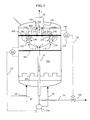
- FIG. 1 illustrates the particular but non-limiting case of a reactor 1 for hydroconversion of a heavy load of hydrocarbons in the presence of hydrogen (H 2 ) and of catalytic particles within a bubbling bed 700.
- Said reactor 1 is supplied with a liquid feed (comprising a mixture of heavy hydrocarbons) via a pipe 10 and a gaseous feed (mainly comprising hydrogen) via a pipe 20, the mixing between the two phases being possible upstream or in the reactor itself.
- Equipment 200 used for the distribution of the liquid and gaseous charges is placed in the lower part of the reactor. These pieces of equipment are, for example, plates with holes or plates fitted with valves, arranged over the entire section of the reactor 1 in a substantially horizontal plane.
- the liquid and gaseous charges are brought into contact with solid catalytic particles of known size and shape and optimized by a person skilled in the art within the bubbling bed 700.
- the catalytic particles are maintained in suspension by the rising speed of the liquid phase. Most often, said speed fixes the rate of expansion of the bed of solid catalytic particles, the gas flow rate being kept constant.
- Level 500 consisting of a slightly turbulent plane due to the agitation caused by the passage of gas bubbles, delimits the zone rich in solid catalytic particles. This level, for a given solid particle inventory, depends solely on the gas and liquid flow rates passing through the reaction zone. Above the level 500, said particles are not significantly entrained.
- the zone situated between the interface 500 delimiting the bed of said particles and the interface 600 consists for the most part of a mixture of a gaseous fraction and a liquid fraction.
- the gaseous fraction flows in the form of bubbles in the continuous liquid fraction.
- Above the interface 600 is an essentially gaseous phase, containing only projections of liquid dispersed in the continuous gaseous phase.
- Boiling of the catalyst is obtained by recycling said liquid fraction in the reactor so as to maintain a suitable liquid surface speed to avoid decantation of solid catalytic particles and to allow a contact time between the liquid, the gas and said particles under the interface 500 long enough to meet the kinetic and thermodynamic constraints of the reaction.
- the liquid is therefore withdrawn from the reactor under the interface 600 by means of equipment 210 which can be a recycling cup most often placed substantially in the center of reactor 1 and preferably conical, for example as described in the US patent 4221653.
- the liquid from the equipment 210 feeds a downcomer 30 then a pump 190.
- the pump 190 When the pump 190 is discharged, the liquid is transported through a conduit 40 and reinjected into the reactor upstream of the distribution means 200.
- the system for supplying the liquid recycling circuit or filling equipment 210 is equipped with devices to promote gas-liquid separation, the training of gas with the recycled liquid being detrimental to the proper functioning of the pump.
- the invention one or more primary separators 280 promoting a vortex effect in the flow.
- These separators can advantageously surround a conduit 220 in which is arranged a propeller inducing a centrifugal movement of the fluids present within said conduit 220.
- the lower opening 230 of conduit 220 connects the area between the interfaces 500 and 600 and the interior of the equipment 210.
- the upper opening 240 of the conduit 220 is located at or near interface 600 whose position can oscillate, during the operation of the reactor, around an average value, for example a distance corresponding to 1 to 20 times the diameter of conduit 220, typically about 3 times.
- Said opening 240 opens onto the inside of a shaped enclosure 290 generally cylindrical.
- the liquid free of the majority of the gas flows down to outside the duct 220 and inside the enclosure 290 and feeds the recycles 210 through an opening 250 located in the space between the vertical walls of the enclosure 290 and the conduit 220.
- the gas, in the form of bubbles, flows towards the part top of enclosure 290 to interface 600 located near opening 240 then is evacuated from this enclosure by an upper opening 270 located above interface 600.
- the disengagement system 210 allowing the supply of the system recycling (30, 190, 40) as described above is located inside the reactor and advantageously has a substantially axial symmetry, generally conical, around of the axis of the reactor 1 enclosure and covers a passage section representing generally between 50 and 100% of the passage section of the reactor, and preferably between 80 to 98% of this section.
- the pump 190 is preferably located outside the reactor but without departing from the scope of the invention may also be internal to said pregnant.
- the liquid products of the reaction are preferably withdrawn upstream of the pump 190 via line 50 as shown in FIG. 1. Without departing from the scope of the invention, said withdrawal can however be carried out downstream of said pump 190.
- the secondary inertials 310 can be positioned downstream of the conduit 270 of each primary separator 280.
- the number of separators 310 is less than or equal to the number of separators 280.
- FIG. 2 shows in more detail the connection between the separator primary 280 and the secondary separator 310.
- a conduit 260 preferably bent, connects the outlet opening 270 of each separator 280 to the inlet opening of a secondary separator 310.
- the separators 310 are cyclones consisting of a cylindrical enclosure comprising an inlet opening 320, an opening of outlet 300 located under the inlet opening 320 and near the interface 600 for discharging the liquid and an opening 265 for discharging the substantially cleaned gas of at least 50% of the liquid having penetrated by 320, located above entry 320 and clearly above interface 600.
- the gas phase still charged with droplets from the primary separator 280 via the conduit 260 enters tangentially through the opening 320 in the cylindrical body of the secondary separator 310 and rotates around the gas outlet conduit 355 located in the center and oriented along the axis principal of said body.
- the liquid coming from the enclosure 310 and discharged through the opening 300 joins the interface 600 by mixing with the fluids located in the cup 210 under the interface 600.
- the gas leaving through the opening 265 flows in the phase essentially gas diluted 800 located above interface 600.
- the gas from the secondary separator 310 then flows to a conduit 70 for discharging the gases (see FIG. 1) through one or more openings made in the wall of the reactor 1 and located above the interface 600 at a greater distance and advantageously close to a tenth of the diameter of the enclosure of the reactor 1.
- the liquid extracted from the gas is discharged through an opening 300 located at the base of the cylinder.
- a device 315 making it possible to avoid the formation of a liquid vortex favoring the entrainment of gas with the liquid, said device comprising for example blades crossed (not shown in Figure 1).
- tertiary inertial separators 350 which can, for example, be cyclones of structure and functioning substantially similar to separators secondary 310 or structured packings.
- the entry opening (s) 330 of the 350 separators connect the diluted and essentially gaseous phase located above the interface 600 inside the enclosure of the separator (s) 350.
- the separators tertiary 350 allow finally obtaining a gaseous effluent substantially cleaned of at least minus 50% of the liquid having entered through the opening 330.
- gas circulating in the conduit 70 contains less than 1% by mass of liquid thanks to the use combined separation means 280, 310 and 350.
- Liquid products from line 30 and substantially free of most of the gases are recycled downstream of the reactor via a liquid recycling line 40 and under the action of a recycle pump 190.
- the liquid effluent contains very small quantities of gas (most often less than 1% by mass) thanks to separation equipment 280, 310 and 350 used above the recycling cup 210.
- measurement and control means can be implemented to ensure proper operation of the reactor.
- the level measurement obtained using this means can feed a regulation loop 175 which, by comparison with the setpoint entered by the operator via a control device 176, controls the speed of rotation of the recycle pump 190. Thanks to such a system, a drop in the level of the interface 500 with respect to a given setpoint is corrected by an increase in the speed of rotation of the pump 190 which induces an increase in the flow rate of recycled liquid in the recycling circuit (30, 40) and results in an increase in speed surface of liquid in the reactor and as a result of the expansion rate of the catalyst bed.
- the level of the interface 600 In order to control the level of the interface 600, one can for example consider evaluating the density profile in the reactor using a differential pressure sensor connected to the reactor by two pressure taps, one 140 located clearly above the interface desired and the other 150 located clearly below this same interface. To avoid the clogging of these pressure taps, we could for example breathe into the taps pressure of known and controlled quantities of gas (e.g. gas charge initial) or liquid (e.g. recycled liquid).
- the level measurement obtained from this way feeds a regulation loop 130 which activates, for example under the action a control member 131, the opening of a valve 100 located on a conduit evacuation 50 of the liquid products from the reactor. Said conduit 50 is preferably placed in diversion on line 30, upstream of pump 190.
- a variation of interface 600 compared to a given setpoint will be corrected respectively by a variation in the opening of the valve 100, a variation in the flow of liquid withdrawn by line 50 and consequently a variation in the fraction of recycled liquid, the flow rates supply of gas and liquid in lines 10 and 20, for example remaining constant.
- FIG. 3 illustrates another embodiment of the invention allowing both the disengagement of the gas in the recycle liquid and the separation of the liquid entrained in the gas flow.
- the gas charged with droplets from the primary separator enters tangentially through the opening 320 of a cyclone 310 of the same kind as that previously described in connection with FIG. 2.
- the primary separators 280 and secondary 310 are not connected, the gas phase still charged with droplets and from the primary separator 280 being initially discharged in the phase essentially gas diluted 800 located above interface 600.
- the recycling means (30, 190, 40) previously described in relation to Figure 1 are separated from the withdrawal means (50, 100) of the liquid phase.
- the evacuation pipe (30) of Figure 1 comprises (illustrated in Figure 4) separate means of racking and recyle.
- the same numbering designates the same elements in the two figures.
- a second pipe 31 is inserted in the down pipe 30, the two pipes being concentric.
- the two lines are fixed in the reactor 1 according to any technique known to those skilled in the art.
- said pipe 31 preferably has a flared shape and truncated. Said upper part is placed between the pressure tapping zones 140 and 150, so that in operation, its inlet port 32 is flush with or either at a level slightly lower than that of interface 600.
- the orifices of liquid phase outlet from separators 280 and 310 are sufficiently far from the orifice inlet 32 allowing the entry of said flush liquid phase in the pipe 31, such that a minimum of gas is entrained with the liquid in said line 31.
- the respective diameters and lengths of the concentric pipes 30 and 31 are sufficiently distinct to allow expansion of the internal pipe 31 without blocking complete or partial of the external pipe 30.
- Another possible solution would be for example the use of materials having different thermal expansion coefficients for the two pipes.
- the stitching of the withdrawal and / or 40 recycling pipes of the liquid fraction may for example be carried out outside or inside reactor 1.
- the gaseous fraction is evacuated at the head of the reactor by the line 70.
- Part of the liquid fraction feeds the pump 190 and the recycling of the liquid phase via line 30.
- another part of said liquid fraction is evacuated via line 31, via opening 32 and feeds line 50 for withdrawing liquid products from the reactor.
- the valve 100 allows the control of the flow of liquid withdrawn.
- the decoupling of the withdrawal means (31, 50, 100) and the recycling means (30, 190, 40) has the advantage of better control of the different interfaces (500, 600) at the reactor level.
- dissociating these means we effectively prevent any loss of boiling of the bed during a wide opening of the valve 100 and / or difficulties in maintaining the interface 600 between the two sockets 150 and 140, for example during variations significant flow rates of withdrawn liquid or injected charge flow rate.
- An alarm system may also be provided in the case where level 600 would come closer to the pressure tapping area 140 and / or the pressure tapping area pressure 150.
Landscapes
- Chemical & Material Sciences (AREA)
- Chemical Kinetics & Catalysis (AREA)
- Engineering & Computer Science (AREA)
- Analytical Chemistry (AREA)
- General Chemical & Material Sciences (AREA)
- Oil, Petroleum & Natural Gas (AREA)
- Devices And Processes Conducted In The Presence Of Fluids And Solid Particles (AREA)
- Degasification And Air Bubble Elimination (AREA)
- Production Of Liquid Hydrocarbon Mixture For Refining Petroleum (AREA)
Abstract
Description
La demande de brevet EP 732,389 propose d'utiliser deux réacteurs en série en incluant un séparateur gaz-liquide entre lesdits deux réacteurs. Une partie du fluide issu du premier réacteur est recyclée vers ledit premier réacteur de façon à maintenir l'ébullition du catalyseur tandis que l'autre partie est envoyée dans ledit séparateur gaz/liquide. La fraction essentiellement liquide résultante de cette séparation alimente ensuite au moins en partie un second réacteur disposé en série.
Pour des raisons économiques, le séparateur placé après le réacteur est bien plus petit que le réacteur et le contrôle du niveau de liquide dans le séparateur externe est par conséquent très difficile dans ce type de procédé.
- un équipement tel qu'une coupelle de recycle muni d'au moins un passage pour ledit mélange, ledit passage pouvant comprendre par exemple une cheminée comprenant préférentiellement des inserts générant un mouvement centrifuge au sein de la ou desdites cheminées,
- un premier élément de séparation ou séparateur primaire placé immédiatement après la ou lesdites cheminées et permettant une séparation dudit mélange en une fraction A contenant la majorité du liquide et une minorité de gaz et une fraction B essentiellement gazeuse contenant une minorité du liquide,
- une première conduite, placée à proximité de la partie supérieure de ladite enceinte, permettant l'évacuation de la fraction B essentiellement gazeuse issue du séparateur primaire,
- une deuxième conduite prolongeant la coupelle de recycle et par laquelle s'écoule gravitairement et est évacuée la fraction A contenant la majorité du liquide issu dudit séparateur primaire,
Selon un premier mode de réalisation de l'invention, chaque séparateur secondaire est relié par une conduite à un séparateur primaire, le nombre de séparateurs primaires étant égal au nombre de séparateurs secondaires.
Le présent dispositif trouve particulièrement son application dans la séparation des effluents issus d'un procédé réactionnel en lit bouillonnant. Par exemple, la présente invention peut être appliquée à l'hydroconversion d'une charge d'hydrocarbures en présence d'hydrogène et de particules catalytiques. Ainsi, dans le cas de l'hydroconversion au sein d'un lit bouillonnant de particules solides catalytiques d'une charge d'hydrocarbures dont le point d'ébullition est supérieur à 360°C, les conditions de pression régnant à l'intérieur de l'enceinte seront typiquement comprises entre 10 et 20 MPa, la température réactionnelle le plus souvent comprise entre 350 et 480°C et le diamètre équivalent des particules solides utilisées avantageusement compris entre 500 microns et 5 mm.
Dans le cas d'un lit bouillonnant, l'invention permet à la fois d'assurer un entraínement minimal de gaz dans le liquide recyclé assurant la mise en mouvement des particules solides et de produire en tête du réacteur un gaz pratiquement exempt de liquide.
Grâce au contrôle du niveau de liquide présent dans l'enceinte et à une séparation interne à l'enceinte réactionnelle des différentes fractions précédemment décrites, l'invention permet en outre de réduire le coût des installations décrites dans l'art antérieur par exemple en supprimant les équipements de séparation externes. La présente invention pourra typiquement être avantageusement appliquée dans le cadre de la modernisation d'unités déjà existantes.
La phase gazeuse encore chargée de gouttelettes issues du séparateur primaire 280 via le conduit 260 entre tangentiellement par l'ouverture 320 dans le corps cylindrique du séparateur secondaire 310 et tourne autour du conduit de sortie du gaz 355 situé au centre et orienté selon l'axe principal dudit corps.
Le liquide issu de l'enceinte 310 et évacué par l'ouverture 300 rejoint l'interface 600 en se mélangeant aux fluides situés dans la coupelle 210 sous l'interface 600. Le gaz sortant par l'ouverture 265 s'écoule dans la phase diluée essentiellement gazeuse 800 située au-dessus de l'interface 600.
Selon un premier mode de réalisation de l'invention, le gaz issu du séparateur secondaire 310 s'écoule ensuite vers un conduit 70 d'évacuation des gaz (voir figure 1) par une ou plusieurs ouvertures pratiquées dans la paroi du réacteur 1 et situées au-dessus de l'interface 600 à une distance supérieure et avantageusement proche d'un dixième du diamètre de l'enceinte du réacteur 1. Le liquide extrait du gaz est évacué grâce à une ouverture 300 située à la base du cylindre. Dans le cas où l'ouverture 300 est située sous l'interface 600, on utilisera avantageusement un dispositif 315 permettant d'éviter la formation d'un vortex liquide favorisant l'entraínement de gaz avec le liquide, ledit dispositif comprenant par exemple des pales croisées (non représentées sur la figure 1).
Claims (13)
- Dispositif de séparation d'un mélange comprenant au moins une phase gazeuse et une phase liquide, ledit mélange étant issu d'une zone de mise en contact d'une charge liquide, d'une charge gazeuse et de particules solides, ledit dispositif étant intégré dans une enceinte et comprenant au moins :ledit dispositif comprenant en outre des moyens de contrôle (130) du niveau d'expansion de ladite phase liquide dans ladite enceinte, lesdits moyens étant configurés de façon à maintenir ledit niveau à une distance de l'orifice de sortie de la fraction B supérieure ou égale à 0,05 fois le diamètre interne de ladite enceinte.un équipement de recycle (210) muni d'au moins un passage pour ledit mélange,un premier élément de séparation (280) ou séparateur primaire placé immédiatement après le ou lesdits passages et permettant une séparation dudit mélange en une fraction A contenant la majorité du liquide et une minorité de gaz et une fraction B essentiellement gazeuse contenant une minorité du liquide,une conduite (70), placée à proximité de la partie supérieure de ladite enceinte, permettant l'évacuation de la fraction B essentiellement gazeuse issue du séparateur primaire,une conduite d'évacuation (30) prolongeant l'équipement de recycle (210) et par laquelle s'écoule gravitairement et est évacuée la fraction A contenant la majorité du liquide issu dudit séparateur primaire,ladite conduite d'évacuation (30) comprenant des moyens séparés de recycle (60, 190, 40) et de soutirage (31, 50) de ladite fraction A,
- Dispositif selon la revendication 1 dans lequel lesdits moyens de soutirage sont constitués par une seconde conduite (31), concentrique à la conduite (30), prolongeant l'équipement de recycle (210), ladite seconde conduite (31) présentant un orifice supérieur (32) placé à proximité du niveau d'expansion de la phase liquide et étant reliée dans sa partie inférieure à des moyens d'évacuation (50) de la fraction A et de contrôle (100, 130) de la phase liquide au sein de ladite enceinte.
- Dispositif selon l'une des revendications 1 ou 2 dans lequel ledit équipement de recycle (210) est de forme conique et placée sensiblement au centre de ladite enceinte.
- Dispositif selon l'une des revendications 1 à 3 dans lequel ladite conduite d'évacuation (30) est reliée à des moyens de recycle (190, 40) dans l'enceinte d'au moins une partie de la fraction A.
- Dispositif selon l'une des revendications 1 à 4 comprenant en outre un deuxième élément de séparation ou séparateur secondaire (310) de type inertiel, permettant la séparation de ladite fraction B en une fraction gazeuse évacuée par la conduite (70) et une fraction liquide évacuée par la conduite (30).
- Dispositif selon l'une quelconque des revendications 1 à 5, dans lequel chaque séparateur secondaire (310) est relié par une conduite (260) à un séparateur primaire (280), le nombre de séparateurs primaires (280) étant égal au nombre de séparateurs secondaires (310).
- Dispositif selon l'une quelconque des revendications 1 à 5, dans lequel chaque séparateur secondaire (310) est relié par une conduite (260) à une pluralité de séparateurs primaires (280).
- Dispositif selon l'une quelconque des revendications 1 à 7 dans lequel le séparateur secondaire (310) n'est pas physiquement relié au séparateur primaire (280), les orifices de sortie du séparateur primaire et d'entrée (320) dudit séparateur secondaire se trouvant dans une partie (800) de l'enceinte contenant une phase essentiellement gazeuse.
- Dispositif selon l'une quelconque des revendications 1 à 8 comprenant un troisième élément de séparation ou séparateur tertiaire (350) de type inertiel, relié dans l'enceinte immédiatement à l'orifice d'entrée du conduit (70), ledit séparateur tertiaire traitant la fraction gazeuse issue du séparateur secondaire.
- Dispositif selon l'une quelconque des revendications 1 à 9 dans lequel ledit équipement (210) est une coupelle de recycle munie d'au moins une cheminée (220) comprenant des inserts générant un mouvement centrifuge au sein de la ou lesdites cheminées (220)
- Dispositif selon l'une quelconque des revendications 1 à 10 dans lequel ledit mélange comprend en outre une phase solide, ladite phase solide étant séparée par le séparateur primaire et évacué par la conduite (30) avec la fraction A contenant la majorité du liquide.
- Application du dispositif selon l'une quelconque des revendications 1 à 11 à la séparation des effluents issus d'un lit bouillonnant.
- Application du dispositif selon l'une quelconque des revendications 1 à 11 à l'hydroconversion d'une charge d'hydrocarbures en présence d'hydrogène et de particules catalytiques.
Priority Applications (2)
| Application Number | Priority Date | Filing Date | Title |
|---|---|---|---|
| EP02291587A EP1374962B1 (fr) | 2002-06-26 | 2002-06-26 | Perfectionnement à un dispositif pour séparer un mélange comprenant au moins une phase gazeuse et une phase liquide, ledit dispositif étant intégré dans une enceinte |
| CA002391597A CA2391597C (fr) | 2002-06-26 | 2002-06-27 | Perfectionnement a un dispositif interne de separation d'un melange comprenant au moins une phase gazeuse et une phase liquide |
Applications Claiming Priority (2)
| Application Number | Priority Date | Filing Date | Title |
|---|---|---|---|
| EP02291587A EP1374962B1 (fr) | 2002-06-26 | 2002-06-26 | Perfectionnement à un dispositif pour séparer un mélange comprenant au moins une phase gazeuse et une phase liquide, ledit dispositif étant intégré dans une enceinte |
| CA002391597A CA2391597C (fr) | 2002-06-26 | 2002-06-27 | Perfectionnement a un dispositif interne de separation d'un melange comprenant au moins une phase gazeuse et une phase liquide |
Publications (2)
| Publication Number | Publication Date |
|---|---|
| EP1374962A1 true EP1374962A1 (fr) | 2004-01-02 |
| EP1374962B1 EP1374962B1 (fr) | 2006-04-05 |
Family
ID=32991640
Family Applications (1)
| Application Number | Title | Priority Date | Filing Date |
|---|---|---|---|
| EP02291587A Expired - Lifetime EP1374962B1 (fr) | 2002-06-26 | 2002-06-26 | Perfectionnement à un dispositif pour séparer un mélange comprenant au moins une phase gazeuse et une phase liquide, ledit dispositif étant intégré dans une enceinte |
Country Status (2)
| Country | Link |
|---|---|
| EP (1) | EP1374962B1 (fr) |
| CA (1) | CA2391597C (fr) |
Cited By (1)
| Publication number | Priority date | Publication date | Assignee | Title |
|---|---|---|---|---|
| CN119368104A (zh) * | 2023-07-26 | 2025-01-28 | 中国石油化工股份有限公司 | 三相分离器及应用该分离器的沸腾床反应器 |
Families Citing this family (2)
| Publication number | Priority date | Publication date | Assignee | Title |
|---|---|---|---|---|
| FR3029802B1 (fr) | 2014-12-11 | 2022-01-07 | Axens | Dispositif permettant de limiter l'entrainement de particules solides en sortie d'un lit fluidise triphasique |
| CN117883830A (zh) * | 2022-10-08 | 2024-04-16 | 中国石油化工股份有限公司 | 三相分离器 |
Citations (3)
| Publication number | Priority date | Publication date | Assignee | Title |
|---|---|---|---|---|
| US3414386A (en) * | 1965-07-15 | 1968-12-03 | Cities Service Res & Dev Co | Reaction vessel for improved temperature regulation in exothermic reactions |
| EP0428796A1 (fr) * | 1987-12-02 | 1991-05-29 | Texaco Development Corporation | Appareillage pour dégazer un liquide dans un procédé en lit entraîné |
| US5066467A (en) * | 1990-10-05 | 1991-11-19 | Texaco Inc. | Liquid degasser in an ebullated bed process |
-
2002
- 2002-06-26 EP EP02291587A patent/EP1374962B1/fr not_active Expired - Lifetime
- 2002-06-27 CA CA002391597A patent/CA2391597C/fr not_active Expired - Fee Related
Patent Citations (3)
| Publication number | Priority date | Publication date | Assignee | Title |
|---|---|---|---|---|
| US3414386A (en) * | 1965-07-15 | 1968-12-03 | Cities Service Res & Dev Co | Reaction vessel for improved temperature regulation in exothermic reactions |
| EP0428796A1 (fr) * | 1987-12-02 | 1991-05-29 | Texaco Development Corporation | Appareillage pour dégazer un liquide dans un procédé en lit entraîné |
| US5066467A (en) * | 1990-10-05 | 1991-11-19 | Texaco Inc. | Liquid degasser in an ebullated bed process |
Cited By (1)
| Publication number | Priority date | Publication date | Assignee | Title |
|---|---|---|---|---|
| CN119368104A (zh) * | 2023-07-26 | 2025-01-28 | 中国石油化工股份有限公司 | 三相分离器及应用该分离器的沸腾床反应器 |
Also Published As
| Publication number | Publication date |
|---|---|
| CA2391597C (fr) | 2007-08-28 |
| CA2391597A1 (fr) | 2003-12-27 |
| EP1374962B1 (fr) | 2006-04-05 |
Similar Documents
| Publication | Publication Date | Title |
|---|---|---|
| EP0403381B1 (fr) | Procédé et dispositif de régulation ou controle du niveau thermique d'un solide pulverulent, comportant un échangeur de chaleur à compartiments en lit fluidisé ou mobile | |
| FR2894849A1 (fr) | Nouveau reacteur a deux zones reactionnelles fluidisees avec systeme de separation gaz/solide integre | |
| FR2675714A1 (fr) | Procede et dispositif d'echange thermique de particules solides pour regeneration en craquage catalytique. | |
| CA2702474C (fr) | Dispositif de separation d'un solide finement divise en suspension dans un liquide visqueux | |
| EP3538627B1 (fr) | Nouveau dispositif de separation gaz liquide pour equiper les reacteurs en lit fluidise triphasique tels que ceux utilises dans le procede h-oil | |
| FR2883200A1 (fr) | Dispositif pour le melange et la repartition d'un gaz et d' un liquide en amont d'un lit granulaire | |
| EP1275425B1 (fr) | Dispositif interne de séparation d'un mélange comprenant au moins une phase gazeuse et une phase liquide | |
| EP1086734B1 (fr) | Système de séparation gaz/liquide intervenant dans un procédé de conversion d'hydrocarbures | |
| WO2018086958A1 (fr) | Nouveau dispositif de separation gaz liquide pour equiper les reacteurs en lit fluidise triphasique tels que ceux utilises dans le procede h-oil | |
| EP2162207B1 (fr) | Enceinte contenant un lit granulaire et une distribution d'une phase gazeuse et d'une phase liquide circulant en un écoulement ascendant dans cette enceinte. | |
| EP1374962B1 (fr) | Perfectionnement à un dispositif pour séparer un mélange comprenant au moins une phase gazeuse et une phase liquide, ledit dispositif étant intégré dans une enceinte | |
| EP3618947A1 (fr) | Nouveau dispositif de distribution de melange polyphasique dans une enceinte comportant un milieu fluidise | |
| US20090269252A1 (en) | Operation of catalyst withdrawal wells with packing | |
| US7060228B2 (en) | Internal device for separating a mixture that comprises at least one gaseous phase and one liquid phase | |
| EP1466958A2 (fr) | Procédé et installation de traitement d'hydrocarbures et de séparation des phases produites par ledit traitement | |
| WO2021115893A1 (fr) | Dispositif et procédé de séparation gaz-solide de craquage catalytique en lit fluidisé avec déflecteur sous fenêtre | |
| FR2767715A1 (fr) | Dispositif de separation et de stripage et son utilisation en craquage catalytique en lit fluidise | |
| EP1800728A1 (fr) | Nouveau système de séparation gaz solide et de stripage pour les unités de craquage catalytique en lit fluidisé | |
| EP3569677B1 (fr) | Dispositif limitateur de vortex et de depots solides | |
| FR3072302A1 (fr) | Dispositif comprenant des injections laterales de liquide pour limiter les phenomenes de depots solides dans les equipements a fond conique | |
| EP2188215B1 (fr) | Procede de separation solide/liquide d'effluent et separateur pour sa mise en oeuvre | |
| WO2021115794A1 (fr) | Dispositif et procédé de séparation gaz-solide de craquage catalytique en lit fluidisé avec paroi externe de préstripage verticale | |
| RU2723020C2 (ru) | Колонна подачи отработавшего катализатора в регенератор, содержащая её система регенерации отработавшего катализатора и способ регенерации отработавшего катализатора с её использованием | |
| FR3100992A1 (fr) | Séparateur gaz/liquide haute pression et procédé de séparation mettant en œuvre un tel séparateur | |
| FR3130832A1 (fr) | Dispositif de séparation gaz-liquide avec une zone d’accompagnement du liquide en sortie, notamment pour réacteur en lit fluidisé triphasique |
Legal Events
| Date | Code | Title | Description |
|---|---|---|---|
| PUAI | Public reference made under article 153(3) epc to a published international application that has entered the european phase |
Free format text: ORIGINAL CODE: 0009012 |
|
| AK | Designated contracting states |
Kind code of ref document: A1 Designated state(s): AT BE CH CY DE DK ES FI FR GB GR IE IT LI LU MC NL PT SE TR |
|
| AX | Request for extension of the european patent |
Extension state: AL LT LV MK RO SI |
|
| 17P | Request for examination filed |
Effective date: 20040702 |
|
| AKX | Designation fees paid |
Designated state(s): BE FI FR IT NL |
|
| AXX | Extension fees paid |
Extension state: SI Payment date: 20040702 |
|
| REG | Reference to a national code |
Ref country code: DE Ref legal event code: 8566 |
|
| 17Q | First examination report despatched |
Effective date: 20050204 |
|
| GRAP | Despatch of communication of intention to grant a patent |
Free format text: ORIGINAL CODE: EPIDOSNIGR1 |
|
| GRAS | Grant fee paid |
Free format text: ORIGINAL CODE: EPIDOSNIGR3 |
|
| GRAA | (expected) grant |
Free format text: ORIGINAL CODE: 0009210 |
|
| AK | Designated contracting states |
Kind code of ref document: B1 Designated state(s): BE FI FR IT NL |
|
| AX | Request for extension of the european patent |
Extension state: SI |
|
| PLBE | No opposition filed within time limit |
Free format text: ORIGINAL CODE: 0009261 |
|
| STAA | Information on the status of an ep patent application or granted ep patent |
Free format text: STATUS: NO OPPOSITION FILED WITHIN TIME LIMIT |
|
| 26N | No opposition filed |
Effective date: 20070108 |
|
| REG | Reference to a national code |
Ref country code: FR Ref legal event code: CD |
|
| REG | Reference to a national code |
Ref country code: FR Ref legal event code: PLFP Year of fee payment: 15 |
|
| REG | Reference to a national code |
Ref country code: FR Ref legal event code: PLFP Year of fee payment: 16 |
|
| REG | Reference to a national code |
Ref country code: FR Ref legal event code: PLFP Year of fee payment: 17 |
|
| PGFP | Annual fee paid to national office [announced via postgrant information from national office to epo] |
Ref country code: FI Payment date: 20200622 Year of fee payment: 19 Ref country code: FR Payment date: 20200626 Year of fee payment: 19 |
|
| PGFP | Annual fee paid to national office [announced via postgrant information from national office to epo] |
Ref country code: BE Payment date: 20200625 Year of fee payment: 19 Ref country code: IT Payment date: 20200618 Year of fee payment: 19 Ref country code: NL Payment date: 20200625 Year of fee payment: 19 |
|
| REG | Reference to a national code |
Ref country code: FI Ref legal event code: MAE |
|
| PG25 | Lapsed in a contracting state [announced via postgrant information from national office to epo] |
Ref country code: FI Free format text: LAPSE BECAUSE OF NON-PAYMENT OF DUE FEES Effective date: 20210626 |
|
| REG | Reference to a national code |
Ref country code: NL Ref legal event code: MM Effective date: 20210701 |
|
| REG | Reference to a national code |
Ref country code: BE Ref legal event code: MM Effective date: 20210630 |
|
| PG25 | Lapsed in a contracting state [announced via postgrant information from national office to epo] |
Ref country code: NL Free format text: LAPSE BECAUSE OF NON-PAYMENT OF DUE FEES Effective date: 20210701 Ref country code: FR Free format text: LAPSE BECAUSE OF NON-PAYMENT OF DUE FEES Effective date: 20210630 |
|
| PG25 | Lapsed in a contracting state [announced via postgrant information from national office to epo] |
Ref country code: IT Free format text: LAPSE BECAUSE OF NON-PAYMENT OF DUE FEES Effective date: 20210626 Ref country code: BE Free format text: LAPSE BECAUSE OF NON-PAYMENT OF DUE FEES Effective date: 20210630 |