EP1374773A1 - System for informing of driver's mental condition - Google Patents
System for informing of driver's mental condition Download PDFInfo
- Publication number
- EP1374773A1 EP1374773A1 EP03013049A EP03013049A EP1374773A1 EP 1374773 A1 EP1374773 A1 EP 1374773A1 EP 03013049 A EP03013049 A EP 03013049A EP 03013049 A EP03013049 A EP 03013049A EP 1374773 A1 EP1374773 A1 EP 1374773A1
- Authority
- EP
- European Patent Office
- Prior art keywords
- driver
- mental condition
- vehicle
- threshold value
- mental
- Prior art date
- Legal status (The legal status is an assumption and is not a legal conclusion. Google has not performed a legal analysis and makes no representation as to the accuracy of the status listed.)
- Granted
Links
Images






Classifications
-
- A—HUMAN NECESSITIES
- A61—MEDICAL OR VETERINARY SCIENCE; HYGIENE
- A61B—DIAGNOSIS; SURGERY; IDENTIFICATION
- A61B5/00—Measuring for diagnostic purposes; Identification of persons
- A61B5/16—Devices for psychotechnics; Testing reaction times ; Devices for evaluating the psychological state
- A61B5/18—Devices for psychotechnics; Testing reaction times ; Devices for evaluating the psychological state for vehicle drivers or machine operators
-
- G—PHYSICS
- G08—SIGNALLING
- G08B—SIGNALLING SYSTEMS, e.g. PERSONAL CALLING SYSTEMS; ORDER TELEGRAPHS; ALARM SYSTEMS
- G08B21/00—Alarms responsive to a single specified undesired or abnormal condition and not otherwise provided for
- G08B21/02—Alarms for ensuring the safety of persons
- G08B21/06—Alarms for ensuring the safety of persons indicating a condition of sleep, e.g. anti-dozing alarms
-
- A—HUMAN NECESSITIES
- A61—MEDICAL OR VETERINARY SCIENCE; HYGIENE
- A61B—DIAGNOSIS; SURGERY; IDENTIFICATION
- A61B5/00—Measuring for diagnostic purposes; Identification of persons
- A61B5/02—Detecting, measuring or recording for evaluating the cardiovascular system, e.g. pulse, heart rate, blood pressure or blood flow
- A61B5/024—Measuring pulse rate or heart rate
-
- Y—GENERAL TAGGING OF NEW TECHNOLOGICAL DEVELOPMENTS; GENERAL TAGGING OF CROSS-SECTIONAL TECHNOLOGIES SPANNING OVER SEVERAL SECTIONS OF THE IPC; TECHNICAL SUBJECTS COVERED BY FORMER USPC CROSS-REFERENCE ART COLLECTIONS [XRACs] AND DIGESTS
- Y10—TECHNICAL SUBJECTS COVERED BY FORMER USPC
- Y10S—TECHNICAL SUBJECTS COVERED BY FORMER USPC CROSS-REFERENCE ART COLLECTIONS [XRACs] AND DIGESTS
- Y10S128/00—Surgery
- Y10S128/92—Computer assisted medical diagnostics
Definitions
- the present invention relates to a driver mental condition information system for informing of a driver's mental condition.
- Systems for providing the driver of a vehicle with information on a driver's mental condition such as sleepiness and fatigue are known (e.g., Japanese Patent Kokai No. 8-140949).
- a driver mental condition information system physiological data of a driver is detected, and a mental condition of the driver is then converted into a numerical value in accordance with the physiological data detected to compare the numerical value with a threshold value, thereby determining whether the mental condition of the driver has become too poor to assure the safe operation of a vehicle due to sleepiness, fatigue or the like. If the mental condition of the driver is determined to have become too poor, a warning is issued to the driver by means of a lamp or sound.
- the conventional system has been designed to present only binary information that allowed a warning to be issued when the numerical value indicative of the mental condition of the driver exceeded the threshold value.
- the system is not able to precisely inform of the driver's mental condition that varied every moment.
- a driver mental condition information system comprises physiological data detecting means for detecting physiological data of a driver of a vehicle, mental condition calculating means for calculating a mental condition of the driver as a mental condition evaluation value in accordance with the physiological data, evaluation threshold value setting means for setting a threshold value for evaluating the mental condition of the driver, and indication means for indicating the mental condition of the driver using the mental condition evaluation value along with the threshold value.
- a method for displaying a driver's mental condition comprises the steps of: detecting physiological data of a driver of a vehicle, calculating a mental condition of the driver as a mental condition evaluation value in accordance with the physiological data, setting a threshold value for evaluating of the mental condition of the driver, and indicating the mental condition of the driver using the mental condition evaluation value along with the threshold value.
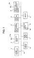
- Fig. 1 is a view showing a driver mental condition information system according to the present invention.
- the driver mental condition information system comprises a system controller 1, a navigation device 2, a physiological data detecting device 3, a driver detecting device 4, a vehicle-to-vehicle wireless communication device 5, a display device 6, a sound output device 7, an operation device 8, and a memory 9.
- the system controller 1, the navigation device 2, the physiological data detecting device 3, the driver detecting device 4, the vehicle-to-vehicle wireless communication device 5, the display device 6, the sound output device 7, and the operation device 8 are connected to each other via a system bus 10.
- the system controller 1 comprises for example, a microcomputer for controlling the entire system.
- the navigation device 2 basically detects a current location of a vehicle in which the system is mounted and allows a map of a surrounding area including the current location to be displayed on the display device 6, thereby providing the driver and a passenger with route guidance for traveling from the current location to a desired destination.
- the navigation device 2 includes a GPS (Global Positioning System) device 11, a vehicle speed sensor 12, an angular speed sensor 13, an acceleration sensor 14, a map data storage device 15, and a navigation controller 16.
- the GPS device 11 connected to a GPS antenna 11a receives at the antenna 11a radio waves transmitted from satellites, and computes the GPS vehicle self-location data, which contains a current location and a traveling direction of the vehicle, based on the received signal.
- the vehicle speed sensor 12, the angular speed sensor 13, and the acceleration sensor 14 are self-contained sensors for detecting vehicle data such as on a location and a traveling direction of the vehicle without obtaining information from outside the vehicle.
- the vehicle speed sensor 12 detects a speed of the vehicle.
- the angular speed sensor 13 detects an angular speed of the vehicle.
- the acceleration sensor 14 detects an acceleration of the vehicle.
- the map data storage device 15 is a drive unit for storage media such as DVD and reads information data such as map data pre-stored on the storage media.
- Te navigation controller 16 is connected to the GPS device 11, the vehicle speed sensor 12, the angular speed sensor 13, the acceleration sensor 14, and the map data storage device 15 to control the entire navigation system.
- the navigation device 2 also generates information on current time.
- the physiological data detecting device 3 detects the number of heartbeats of the driver and then outputs physiological data indicative of the number of heartbeats.
- the physiological data detecting device 3 detects the conduction state of electrodes and the potential difference therebetween when the driver grips the steeling wheel of the vehicle, thereby providing the physiological data.
- the physiological data detecting device 3 is provided with a pair of electrodes 102a, 102b, generally denoted by 102, and a pair of electrodes 103a, 103b, generally denoted by 103.
- the electrodes 102 are each separately installed on the outer and inner positions on the left side of a steering wheel 101, where the driver places his or her left hand.
- the electrodes 103 are each separately installed on the outer and inner positions on the right side of the steering wheel 101, where the driver places his or her right hand.
- the electrodes 102a, 103a are individually supplied with the same constant current at a terminal V from a power source (not shown), while although not illustrated, the electrodes 102b, 103b are both connected to the ground.
- a left-hand skin resistance 104 is inserted between the electrodes 102a, 102b, which constitute the left-hand electrodes 102
- a right-hand skin resistance 105 is inserted between the electrodes 103a, 103b, which constitute the right-hand electrodes 103.
- the potentials at the electrodes 102a, 103a are each supplied to a differential amplifier 107.
- the differential amplifier 107 amplifies the potential difference between both the electrodes and then outputs a heartbeat signal at a limited frequency band.
- the heartbeat signal is supplied to a heartbeat rate counter 108.
- the heartbeat rate counter 108 counts the number of heartbeats (heartbeat rate) as physiological data in accordance with the heartbeat signal.
- the peripheral bloodstream in a hand placed on the steering wheel is detected with an optical sensor installed at the steering wheel using so-called pulse waves.
- the heart can be irradiated with weak microwaves generated by a high frequency circuit installed in a seat belt or the like to analyze the difference between the irradiation signal and its return signal, thereby measuring heartbeats.
- the number of heartbeats usually increases in a nervous or irritating condition. A change in these conditions can be judged in accordance with an electrocardiography to thereby evaluate the mental condition of the driver.
- using skin resistance, perspiration or the electrodermal reaction (different from the electrocardiography) between the right and left hands can also be examined, thereby judging the mental condition.
- the driver's mental condition can be thus grasped with higher accuracy in combination with the electrodermal reaction indicative of a temporary tension.
- the driver detecting device 4 is a sensor for detecting information on a driver to identify the driver. For example, the driver detecting device 4 detects a parameter by which the driver is identified, such as the voice pattern, iris, or fingerprint of the driver. The driver detection data indicative of the driver's parameter is supplied to the system controller 1 via the system bus 10.
- the vehicle-to-vehicle wireless communication device 5 provided to communicate with other vehicles, transmits and receives radio signals via an antenna 5a.
- information in the radio signal transmitted contains vehicle ID information for identifying the vehicle, driver information indicative of the driver, data on a current location and a traveling speed of the vehicle, and sleepiness information.
- the data to be sent is supplied from the system controller 1 to the vehicle-to-vehicle wireless communication device 5 via the system bus 10, while the data received at the vehicle-to-vehicle wireless communication device 5 is supplied from the vehicle-to-vehicle wireless communication device 5 to the system controller 1 via the system bus 10. It is possible to utilize an on-board telephone or a cellular phone as the vehicle-to-vehicle wireless communication device 5.
- the display device 6 is for example, a liquid crystal display device, displays information instructed by the system controller 1 or the navigation device 2. Although detailed later, the information to be displayed includes a map, levels of sleepiness, a red zone, and a warning indication.
- the sound output device 7 issues a warning sound in response to an instruction from the system controller 1.
- the operation device 8 receives an operational input provided by a user such as a driver.
- the operation device 8 is provided with a setting switch 8a which the driver operates to generate a sleepiness setting request signal and send it to the system bus 10.
- the drowsy driver will depress the setting switch 8a.
- the system controller 1 provides operational control to the memory 9 to store a variety of data therein.
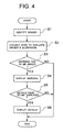
- step S1 a determination is made in accordance with the driver detection data output from the driver detecting device 4. That is, if the driver parameters available to identify the driver have already been registered, the associated driver is identified in accordance with the driver detection data. An unregistered driver has to input his or her name at the operation device 8 to be identified.
- step S2 the system controller 1 collects map data and navigation data from the navigation device 2 and physiological data from the physiological data detecting device 3 to perform a sleepiness evaluation operation (step S2).
- a sleepiness evaluation value Pn is calculated in accordance with the physiological data to determine whether the sleepiness evaluation value Pn is greater than a sleepiness evaluation threshold value SN to fall within a red zone. Further information on the sleepiness evaluation operation can be found in Japanese Patent Kokai No. 8-140949, and will not be detailed herein. However, a method for calculating the sleepiness evaluation value Pn is not limited to the one disclosed in Japanese Patent Kokai No. 8-140949, but any other methods can also be employed.
- step S3 the controller 1 judges that a sleepiness warning should be issued. Therefore, since the sleepiness evaluation value Pn is a value in the red zone, a warning is displayed on the display device 6 (step S4).
- Fig. 5 is a view showing an example of a mental condition display window displayed on the display device 6.
- a mental condition display window displayed on the display device 6.
- variations in the driver sleepiness evaluation value with time are shown in a graph 54 while a red zone 55 for the driver is also shown at the same time.
- the display is presented so that up/down correction buttons 56, 57 displayed or the operation device 8 can be operated to adjust the range of the red zone 55 or the sleepiness evaluation threshold value SN.
- brief traffic information 58 is also displayed within the window frame 53.
- the mental condition display window may be displayed beside a usual navigation window or switched over to a navigation window or vice versa through an operation at the operation device 8.
- the display window makes it possible for the driver to grasp variations in his or her own mental condition during driving.
- the warning displayed in step S4 on such a mental condition display window shows that the graph 54 representing the sleepiness evaluation value falls within the range of the red zone 55 as shown in Fig. 5, while the warning is presented visibly and audibly in a predetermined form.
- traffic information on the route to the nearest service area is displayed in a window for the traffic information 58.
- the process may provide control such that the mental condition display window is forcedly displayed on the display device 6.
- the system controller 1 also determines whether details have to be displayed (step S5). For example, if the driver operates the operation device 8 to require details to be displayed, the system controller 1 determines that the details have to be displayed.
- the process reads out the maximum value, an average value, and the minimum value of the sleepiness evaluation value Pn from a predetermined area in the memory 9 to display the details (step S6).
- the details to be displayed include variations in physiological data (heartbeat rate) and its average value, which are indicated in the graph as shown in Fig. 6. In the details displayed, also included is the current heartbeat rate.
- the operation for adjusting the red zone 55 is described below.
- the system controller 1 executes a red zone adjustment routine while displaying a warning.
- the description will be given to a case where adjustments are made by means of the up/down correction buttons 56, 57 displayed.
- the operations carried out by the driver on the up/down correction buttons 56, 57 are individually detected by means of a touch switch (not shown), and the detected contents are supplied to the system controller 1 via the system bus 10.
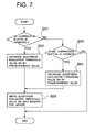
- the process first determines whether the up correction button 56 has been operated (step S51). If the up correction button 56 has been operated, the sleepiness evaluation threshold value SN of the driver is increased by a predetermined value (e.g., one)(step S52). On the other hand, if the up correction button 56 has not been operated, the process determines whether the down correction button 57 has been operated (step S53). If the down correction button 57 has been operated, the sleepiness evaluation threshold value SN of the driver is decreased by a predetermined value (step S54). After step S52 or S54 has been completed, the sleepiness evaluation threshold value SN is written into the memory 9 for update (step S55). The sleepiness evaluation threshold value SN is that of the driver identified in step S1, and the sleepiness evaluation threshold value SN of the driver identified in step S1 is updated in step S55.
- a predetermined value e.g., one
- the processing in the red zone adjustment routine allows the sleepiness evaluation threshold value SN to be properly set for each driver. This enables a warning to sleepiness to be issued to each driver at a proper timing.
- the operation device 8 can also be operated so that the red zone adjustment routine is executed at a desired point in time.
- the driver can operate a predetermined button (e.g., a sleepiness button, described below) at the operation device 8 when the driver actually feels sleepy, such that the sleepiness evaluation value Pn at that time point is employed as the sleepiness evaluation threshold value SN.
- a predetermined button e.g., a sleepiness button, described below
- the system controller 1 determines whether the sleepiness button has been operated (step S61). If the sleepiness button has been operated, the process reads out a sleepiness evaluation value Pn stored in the memory 9 (step S62), and then writes the sleepiness evaluation value Pn in the memory 9 as a sleepiness evaluation threshold value SN (step S63).
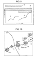
- step S4 the warning can be displayed as shown in Fig. 9.
- the example of displaying the warning shows that a driver "B” drove the same vehicle after a driver "A” had driven it.
- information on variations in the sleepiness evaluation values Pn of the drivers A, B is plotted in conjunction with the display of their red zones 55 as well as a message 59, "Sleepiness is detected.”
- the system controller 1 reads out, as shown in Fig. 11, the sleepiness evaluation value Pn and the location of the vehicle at a current time, the sleepiness evaluation value Pn and the location of the vehicle at a time of a predetermined period X (e.g., ten minutes) before the current time, and the sleepiness evaluation value Pn and the location of the vehicle at a time of a predetermined period 2X before the current time point (step S71), and further reads the sleepiness evaluation threshold value SN (step S72).
- a predetermined period X e.g., ten minutes
- the controller 1 then creates a red zone frame corresponding to the sleepiness evaluation threshold value SN (step S73), and then defines the size of a circle in the red zone for each of the current sleepiness evaluation value Pn, the sleepiness evaluation value Pn at the time of X before the current time, and the sleepiness evaluation value Pn at the time of 2X before the current time, thereby creating display data (step S74).
- the size of a circle increases in the central portion of the red zone frame as the sleepiness evaluation value Pn increases.
- the system controller 1 acquires the current locations of other vehicles and the sleepiness evaluation value Pn via the vehicle-to-vehicle wireless communication device 5 (step S75), and then creates display data (step S76).
- the system controller 1 supplies, to the display device 6, the display data of its own vehicle created in step S74 and the display data of the other vehicles created in step S76 in conjunction with their respective location data (step S77).
- the display device 6 then processes the supplied display data for display and then superimposes the resulting data as shown in Fig. 10 on the map indicated by the map data from the navigation device 2. For example, on the map displayed, the sleepiness evaluation value Pn at the time of 2X before the current time is displayed at the self-location of the vehicle at the time of 2X before the current time on the traveled path as a marker 71 having a circular size corresponding to a sleepiness level 1.
- the sleepiness evaluation value Pn at the time of X before the current time at the self-location of the vehicle at the time of X before the current time is displayed as a marker 72 having a circular size corresponding to a sleepiness level 2, with the current sleepiness evaluation value Pn displayed at the current location of the vehicle as a marker 73 having a circular size corresponding to a sleepiness level 3.
- the current locations of the other vehicles are indicated with markers 74, 75 in other shapes.
- the markers 74, 75 may be different in shape from driver to driver as shown in Fig. 10 or shaped corresponding to the level of sleepiness.
- the markers of the vehicle itself and other vehicles are not limited to the aforementioned examples, e.g., the current mental condition information evaluation value or the evaluation threshold value such as for sleepiness levels may also be indicated in accordance with not only the size of markers but also the color or pattern thereof. On the other hand, the shape or the like of the markers may be changed depending on the mental condition such as sleepiness, fatigue, and irritation.
- the driver's mental conditions of the vehicle itself and other vehicles can be displayed in conjunction with information on their respective locations, however, when the sleepiness or the like of the driver has been detected, the nearest service area may be displayed, followed by a navigational operation performed at the same time.
- the present invention has been described with reference to, but not limited to, the case where the driver's sleepiness is determined, however, another mental condition such as fatigue, strain, and irritation may also be determined.
- the physiological data is not limited to the heartbeat rate of the driver, but other physiological data such as fluctuations in heartbeat, respiratory rate, and blood pressure may also be detected.
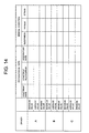
- the database as shown in Fig. 13 is formed when various types of vehicle data and physiological data are detected and various types of mental conditions are determined.
- the physiological data and the mental condition are stored in a database with the maximum value, an average value, and the minimum value.
- information on changes in mental condition is visually presented to the driver; however, the information on changes in mental condition may also be presented with variations in sound (e.g., changes in frequency of the sound generated).
- the system according to the present invention comprises evaluation threshold value setting means for setting a threshold value for evaluating the mental condition of a driver and presentation means for presenting the mental condition of the driver using a mental condition evaluation value in conjunction with the evaluation threshold value, thereby making it possible to precisely inform of the mental condition of the driver of a vehicle.
Landscapes
- Health & Medical Sciences (AREA)
- Life Sciences & Earth Sciences (AREA)
- Physics & Mathematics (AREA)
- Engineering & Computer Science (AREA)
- Heart & Thoracic Surgery (AREA)
- Surgery (AREA)
- Psychiatry (AREA)
- Psychology (AREA)
- Social Psychology (AREA)
- Educational Technology (AREA)
- Developmental Disabilities (AREA)
- Biophysics (AREA)
- Pathology (AREA)
- Biomedical Technology (AREA)
- Child & Adolescent Psychology (AREA)
- Medical Informatics (AREA)
- Molecular Biology (AREA)
- Hospice & Palliative Care (AREA)
- Animal Behavior & Ethology (AREA)
- General Health & Medical Sciences (AREA)
- Public Health (AREA)
- Veterinary Medicine (AREA)
- Business, Economics & Management (AREA)
- Emergency Management (AREA)
- General Physics & Mathematics (AREA)
- Measurement Of The Respiration, Hearing Ability, Form, And Blood Characteristics Of Living Organisms (AREA)
- Auxiliary Drives, Propulsion Controls, And Safety Devices (AREA)
- Measuring Pulse, Heart Rate, Blood Pressure Or Blood Flow (AREA)
- Measurement And Recording Of Electrical Phenomena And Electrical Characteristics Of The Living Body (AREA)
- Navigation (AREA)
Abstract
Description
Claims (13)
- A driver mental condition information system comprisingphysiological data detecting means for detecting physiological data of a driver of a vehicle,mental condition calculating means for calculating a mental condition of the driver as a mental condition evaluation value in accordance with the physiological data,evaluation threshold value setting means for setting a threshold value for evaluating the mental condition of the driver, andindication means for indicating the mental condition of the driver using the mental condition evaluation value along with the threshold value.
- A driver mental condition information system according to claim 1, further comprisingstorage means for sequentially storing the mental condition evaluation value calculated by said mental condition calculating means, whereinsaid indication means indicates a variation in mental condition of the driver using the mental condition evaluation value stored in said storage means along with the threshold value.
- A driver mental condition information system according to claim 1, further comprisingdriver identifying means for identifying a driver of the vehicle, whereinsaid evaluation threshold value setting means is allowed to set the threshold value at a desired value for each driver identified by said driver identifying means, andsaid indication means indicates the mental condition evaluation value of the driver along with the threshold value corresponding to the driver identified by said driver identifying means.
- A driver mental condition information system according to claim 1, whereinsaid evaluation threshold value setting means has adjusting means for adjusting the threshold value in response to an input operation.
- A driver mental condition information system according to claim 1, further comprisingmental condition evaluation means for comparing the mental condition evaluation value with the threshold value to evaluate the mental condition of the driver, whereinsaid indication means displays the mental condition of the driver as a warning when the mental condition of the driver is detected as a predetermined condition by said mental condition evaluation means.
- A driver mental condition information system according to claim 2, whereinsaid storage means has a database for storing physiological data, the mental condition evaluation value, and the threshold value for each driver.
- A driver mental condition information system according to claim 5, further comprisingself-location detecting means for detecting a self-location of the vehicle, whereinsaid indication means indicates a nearest service area when the mental condition of the driver is detected as a predetermined condition by said mental condition evaluation means.
- A driver mental condition information system according to claim 1, further comprisingself-location detecting means for detecting a self-location of the vehicle, anda navigation device for outputting display map data indicative of a map including the self-location of the vehicle detected by said self-location detecting means, whereinsaid indication means displays a map in accordance with the display map data, and displays the mental condition evaluation value of the driver at each point on a travel path corresponding to the self-location detected by said navigation device on the map displayed.
- A driver mental condition information system according to claim 8, whereinsaid indication means displays the threshold value along with the mental condition evaluation value displayed on said display map.
- A driver mental condition information system according to claim 8, whereinsaid indication means displays the mental condition evaluation value of the driver at each point on said travel path as a variation in shape size, color, or pattern.
- A driver mental condition information system according to claim 8, further comprisingvehicle-to-vehicle wireless communication means for collecting, by radio waves, a location and a mental condition evaluation value of a driver of another vehicle near the vehicle, whereinsaid indication means displays the mental condition evaluation value of the driver of the other vehicle at a position of said display map corresponding to the location of the other vehicle collected by said vehicle-to-vehicle wireless communication means.
- A driver mental condition information system according to claim 8, whereinwhen a mental condition of the driver is detected as a predetermined condition by said mental condition evaluation means, said indication means indicates a nearest service area and executes a navigational guidance operation for leading to the service area.
- A method for displaying a driver's mental condition comprising the steps of:detecting physiological data of a driver of a vehicle,calculating a mental condition of the driver as a mental condition evaluation value in accordance with the physiological data,setting a threshold value for evaluating of the mental condition of the driver, andindicating the mental condition of the driver using the mental condition evaluation value along with the threshold value.
Applications Claiming Priority (2)
| Application Number | Priority Date | Filing Date | Title |
|---|---|---|---|
| JP2002188285A JP3846872B2 (en) | 2002-06-27 | 2002-06-27 | Driver mental state information provision system |
| JP2002188285 | 2002-06-27 |
Publications (2)
| Publication Number | Publication Date |
|---|---|
| EP1374773A1 true EP1374773A1 (en) | 2004-01-02 |
| EP1374773B1 EP1374773B1 (en) | 2005-10-19 |
Family
ID=29717653
Family Applications (1)
| Application Number | Title | Priority Date | Filing Date |
|---|---|---|---|
| EP03013049A Expired - Lifetime EP1374773B1 (en) | 2002-06-27 | 2003-06-10 | System for informing of driver's mental condition |
Country Status (4)
| Country | Link |
|---|---|
| US (1) | US6960168B2 (en) |
| EP (1) | EP1374773B1 (en) |
| JP (1) | JP3846872B2 (en) |
| DE (1) | DE60301910T2 (en) |
Cited By (5)
| Publication number | Priority date | Publication date | Assignee | Title |
|---|---|---|---|---|
| WO2007141462A1 (en) * | 2006-06-09 | 2007-12-13 | Universite Joseph Fourier | Method and device for assisting the driving of a motor vehicle |
| EP2322904A1 (en) * | 2009-11-17 | 2011-05-18 | Honeywell International Inc. | Navigation based on cognitive and/or physiological data |
| WO2016115053A1 (en) * | 2015-01-12 | 2016-07-21 | Harman International Industries, Incorporated | Cognitive load driving assistant |
| WO2016202450A1 (en) * | 2015-06-19 | 2016-12-22 | Audi Ag | A method for controlling an interface device of a motor vehicle |
| WO2016206790A1 (en) * | 2015-06-24 | 2016-12-29 | Audi Ag | A method for operating a motor vehicle, determination device and motor vehicle with a determination device |
Families Citing this family (56)
| Publication number | Priority date | Publication date | Assignee | Title |
|---|---|---|---|---|
| JP4111062B2 (en) * | 2003-05-27 | 2008-07-02 | 株式会社デンソー | Sleepiness level detection device |
| JP2005315802A (en) * | 2004-04-30 | 2005-11-10 | Olympus Corp | User support device |
| USD545140S1 (en) | 2004-07-29 | 2007-06-26 | Kai R$D Center Co., Ltd. | Handle for a knife |
| JP4502844B2 (en) * | 2005-02-25 | 2010-07-14 | アルパイン株式会社 | Warning device and warning method |
| JP4645891B2 (en) * | 2005-03-24 | 2011-03-09 | 日本精機株式会社 | Vehicle driving support apparatus and vehicle driving support method |
| JP4591328B2 (en) * | 2005-11-18 | 2010-12-01 | 株式会社デンソー | Vehicle running state detection device, navigation device, and program |
| US20090209829A1 (en) * | 2006-03-24 | 2009-08-20 | Pioneer Corporation | Apparatus for detecting driver's mental state and method for detecting mental state |
| JP4895097B2 (en) * | 2006-03-27 | 2012-03-14 | マツダ株式会社 | Occupant status detection device |
| US9067565B2 (en) | 2006-05-22 | 2015-06-30 | Inthinc Technology Solutions, Inc. | System and method for evaluating driver behavior |
| US7859392B2 (en) | 2006-05-22 | 2010-12-28 | Iwi, Inc. | System and method for monitoring and updating speed-by-street data |
| WO2008055078A2 (en) * | 2006-10-27 | 2008-05-08 | Vivometrics, Inc. | Identification of emotional states using physiological responses |
| JP4793650B2 (en) * | 2006-11-07 | 2011-10-12 | アイシン精機株式会社 | Physical condition management system |
| JP4211841B2 (en) * | 2006-11-15 | 2009-01-21 | トヨタ自動車株式会社 | Driver state estimation device, server, driver information collection device, and driver state estimation system |
| JP2008132012A (en) * | 2006-11-27 | 2008-06-12 | Denso Corp | Pulse wave detector |
| JP2008234009A (en) * | 2007-03-16 | 2008-10-02 | Denso Corp | Health management support system |
| US9129460B2 (en) * | 2007-06-25 | 2015-09-08 | Inthinc Technology Solutions, Inc. | System and method for monitoring and improving driver behavior |
| US8818618B2 (en) | 2007-07-17 | 2014-08-26 | Inthinc Technology Solutions, Inc. | System and method for providing a user interface for vehicle monitoring system users and insurers |
| US9117246B2 (en) | 2007-07-17 | 2015-08-25 | Inthinc Technology Solutions, Inc. | System and method for providing a user interface for vehicle mentoring system users and insurers |
| US7876205B2 (en) | 2007-10-02 | 2011-01-25 | Inthinc Technology Solutions, Inc. | System and method for detecting use of a wireless device in a moving vehicle |
| JP5115704B2 (en) * | 2007-10-31 | 2013-01-09 | 株式会社エクォス・リサーチ | Steering |
| US8416067B2 (en) | 2008-09-09 | 2013-04-09 | United Parcel Service Of America, Inc. | Systems and methods for utilizing telematics data to improve fleet management operations |
| US11482058B2 (en) | 2008-09-09 | 2022-10-25 | United Parcel Service Of America, Inc. | Systems and methods for utilizing telematics data to improve fleet management operations |
| KR101173944B1 (en) * | 2008-12-01 | 2012-08-20 | 한국전자통신연구원 | System and method for controlling sensibility of driver |
| JP2010134534A (en) * | 2008-12-02 | 2010-06-17 | Toyota Motor Corp | Driving support device |
| JP2010140358A (en) * | 2008-12-12 | 2010-06-24 | Toyota Motor Corp | Traveling support device |
| US8963702B2 (en) | 2009-02-13 | 2015-02-24 | Inthinc Technology Solutions, Inc. | System and method for viewing and correcting data in a street mapping database |
| US20100234692A1 (en) * | 2009-03-13 | 2010-09-16 | Bo-Jau Kuo | System for health management used in vehicle and method thereof |
| KR101303648B1 (en) * | 2009-12-08 | 2013-09-04 | 한국전자통신연구원 | Sensing Device of Emotion Signal and method of the same |
| DE102010048273A1 (en) | 2010-10-12 | 2011-05-26 | Daimler Ag | Method for alert-dependent initialization of vehicle action, involves determining vehicle position on digital road map of navigation system, where local vehicle environment is determined as environment sensor data by vehicle-sensor device |
| US9953468B2 (en) | 2011-03-31 | 2018-04-24 | United Parcel Service Of America, Inc. | Segmenting operational data |
| US9208626B2 (en) | 2011-03-31 | 2015-12-08 | United Parcel Service Of America, Inc. | Systems and methods for segmenting operational data |
| JP5652324B2 (en) * | 2011-05-19 | 2015-01-14 | 株式会社デンソー | Massage equipment |
| US8766819B2 (en) * | 2011-06-17 | 2014-07-01 | The Boeing Company | Crew allertness monitoring of biowaves |
| WO2014176473A1 (en) * | 2013-04-25 | 2014-10-30 | GM Global Technology Operations LLC | Situation awareness system and method |
| US9172477B2 (en) | 2013-10-30 | 2015-10-27 | Inthinc Technology Solutions, Inc. | Wireless device detection using multiple antennas separated by an RF shield |
| US9805521B1 (en) | 2013-12-03 | 2017-10-31 | United Parcel Service Of America, Inc. | Systems and methods for assessing turns made by a vehicle |
| JP6270580B2 (en) * | 2014-03-26 | 2018-01-31 | 本田技研工業株式会社 | Vehicle information terminal |
| US9618359B2 (en) * | 2014-09-25 | 2017-04-11 | Intel Corporation | Wearable sensor data to improve map and navigation data |
| DE102015200775A1 (en) * | 2015-01-20 | 2016-07-21 | Bayerische Motoren Werke Aktiengesellschaft | Independent assessment of an emotional state and a cognitive burden |
| JP2016182242A (en) * | 2015-03-26 | 2016-10-20 | パイオニア株式会社 | Drowsiness calculation device |
| US10309788B2 (en) | 2015-05-11 | 2019-06-04 | United Parcel Service Of America, Inc. | Determining street segment headings |
| US10328852B2 (en) * | 2015-05-12 | 2019-06-25 | University Of North Dakota | Systems and methods to provide feedback to pilot/operator by utilizing integration of navigation and physiological monitoring |
| JP6380295B2 (en) * | 2015-08-25 | 2018-08-29 | マツダ株式会社 | Driver status detection device |
| US20170105667A1 (en) * | 2015-10-15 | 2017-04-20 | Josh WEI | Stress and Heart Rate Trip Monitoring System and Method |
| JP6175476B2 (en) * | 2015-12-01 | 2017-08-02 | 本田技研工業株式会社 | Vehicle steering device |
| JP6698437B2 (en) * | 2016-06-14 | 2020-05-27 | サンスター株式会社 | Computer, display method, and computer control program |
| WO2018027407A1 (en) * | 2016-08-06 | 2018-02-15 | 吕秋萍 | Data collection method for iris matched speed limiting technology, and speed limiting system |
| WO2018027406A1 (en) * | 2016-08-06 | 2018-02-15 | 吕秋萍 | Method for limiting top speed based on iris, and speed limiting system |
| US10249194B2 (en) * | 2016-08-30 | 2019-04-02 | International Business Machines Corporation | Modifying behavior of autonomous vehicle based on advanced predicted behavior analysis of nearby drivers |
| US10192171B2 (en) * | 2016-12-16 | 2019-01-29 | Autonomous Fusion, Inc. | Method and system using machine learning to determine an automotive driver's emotional state |
| JP2019093175A (en) * | 2019-02-05 | 2019-06-20 | パイオニア株式会社 | Drowsiness calculation device |
| KR20210143344A (en) * | 2019-04-19 | 2021-11-29 | 엘지전자 주식회사 | Vehicle control device and control method of the device |
| JP7302275B2 (en) * | 2019-05-15 | 2023-07-04 | 株式会社デンソー | Drowsiness estimation device |
| JP7234846B2 (en) * | 2019-07-30 | 2023-03-08 | 富士通株式会社 | Information processing device, near-miss detection method, and near-miss detection system |
| JP2021003560A (en) * | 2020-08-26 | 2021-01-14 | パイオニア株式会社 | Drowsiness calculation device |
| CN112336349B (en) * | 2020-10-12 | 2024-05-14 | 易显智能科技有限责任公司 | Method and related device for identifying psychological state of driver |
Citations (4)
| Publication number | Priority date | Publication date | Assignee | Title |
|---|---|---|---|---|
| US4706072A (en) * | 1983-11-30 | 1987-11-10 | Aisin Seiki Kabushiki Kaisha | Human condition monitoring and security controlling apparatus on a road-vehicle |
| EP0713675A2 (en) * | 1994-11-16 | 1996-05-29 | Pioneer Electronic Corporation | Driving mental condition detecting apparatus |
| WO1996016830A1 (en) * | 1994-11-28 | 1996-06-06 | The Driver Alert Technology Company Limited | Driver alertness monitor |
| WO2000044580A1 (en) * | 1999-01-27 | 2000-08-03 | Compumedics Sleep Pty. Ltd. | Vigilance monitoring system |
Family Cites Families (11)
| Publication number | Priority date | Publication date | Assignee | Title |
|---|---|---|---|---|
| JPS6076428A (en) * | 1983-09-30 | 1985-04-30 | Aisin Seiki Co Ltd | Driving condition warning device |
| JPS61244327A (en) * | 1985-04-23 | 1986-10-30 | 株式会社日本自動車部品総合研究所 | Pulse meter for driver |
| JP2809338B2 (en) * | 1994-08-23 | 1998-10-08 | 住友電気工業株式会社 | Navigation device |
| JPH0944800A (en) * | 1995-07-26 | 1997-02-14 | Mitsubishi Electric Corp | Car information system |
| JP3992314B2 (en) * | 1996-12-13 | 2007-10-17 | いすゞ自動車株式会社 | Doze driving detection device |
| JPH10288532A (en) * | 1997-04-15 | 1998-10-27 | Toyota Motor Corp | Voice guidance device for vehicles |
| JPH11151231A (en) * | 1997-11-20 | 1999-06-08 | Nissan Motor Co Ltd | Mental fatigue evaluation device for vehicles |
| JPH11314534A (en) * | 1998-05-06 | 1999-11-16 | Nissan Motor Co Ltd | Prevention device for caution ability reduction for vehicles |
| JP2000247195A (en) * | 1999-02-25 | 2000-09-12 | Nissan Motor Co Ltd | Vehicle control device |
| KR100382154B1 (en) * | 2000-02-22 | 2003-05-01 | 박원희 | Device For Sensing Of Driver's Condition |
| US6599243B2 (en) * | 2001-11-21 | 2003-07-29 | Daimlerchrysler Ag | Personalized driver stress prediction using geographical databases |
-
2002
- 2002-06-27 JP JP2002188285A patent/JP3846872B2/en not_active Expired - Fee Related
-
2003
- 2003-06-06 US US10/455,726 patent/US6960168B2/en not_active Expired - Fee Related
- 2003-06-10 EP EP03013049A patent/EP1374773B1/en not_active Expired - Lifetime
- 2003-06-10 DE DE60301910T patent/DE60301910T2/en not_active Expired - Lifetime
Patent Citations (5)
| Publication number | Priority date | Publication date | Assignee | Title |
|---|---|---|---|---|
| US4706072A (en) * | 1983-11-30 | 1987-11-10 | Aisin Seiki Kabushiki Kaisha | Human condition monitoring and security controlling apparatus on a road-vehicle |
| EP0713675A2 (en) * | 1994-11-16 | 1996-05-29 | Pioneer Electronic Corporation | Driving mental condition detecting apparatus |
| JPH08140949A (en) * | 1994-11-16 | 1996-06-04 | Pioneer Electron Corp | Driving mental condition detector |
| WO1996016830A1 (en) * | 1994-11-28 | 1996-06-06 | The Driver Alert Technology Company Limited | Driver alertness monitor |
| WO2000044580A1 (en) * | 1999-01-27 | 2000-08-03 | Compumedics Sleep Pty. Ltd. | Vigilance monitoring system |
Cited By (7)
| Publication number | Priority date | Publication date | Assignee | Title |
|---|---|---|---|---|
| WO2007141462A1 (en) * | 2006-06-09 | 2007-12-13 | Universite Joseph Fourier | Method and device for assisting the driving of a motor vehicle |
| EP2322904A1 (en) * | 2009-11-17 | 2011-05-18 | Honeywell International Inc. | Navigation based on cognitive and/or physiological data |
| WO2016115053A1 (en) * | 2015-01-12 | 2016-07-21 | Harman International Industries, Incorporated | Cognitive load driving assistant |
| US10399575B2 (en) | 2015-01-12 | 2019-09-03 | Harman International Industries, Incorporated | Cognitive load driving assistant |
| WO2016202450A1 (en) * | 2015-06-19 | 2016-12-22 | Audi Ag | A method for controlling an interface device of a motor vehicle |
| WO2016206790A1 (en) * | 2015-06-24 | 2016-12-29 | Audi Ag | A method for operating a motor vehicle, determination device and motor vehicle with a determination device |
| CN106274479A (en) * | 2015-06-24 | 2017-01-04 | 奥迪股份公司 | Operate the method for motor vehicles and determine device |
Also Published As
| Publication number | Publication date |
|---|---|
| JP2004024704A (en) | 2004-01-29 |
| DE60301910D1 (en) | 2006-03-02 |
| JP3846872B2 (en) | 2006-11-15 |
| EP1374773B1 (en) | 2005-10-19 |
| DE60301910T2 (en) | 2006-07-20 |
| US20040002638A1 (en) | 2004-01-01 |
| US6960168B2 (en) | 2005-11-01 |
Similar Documents
| Publication | Publication Date | Title |
|---|---|---|
| EP1374773B1 (en) | System for informing of driver's mental condition | |
| US6870478B2 (en) | Information providing system and information providing method | |
| EP1891490B1 (en) | Dialogue system | |
| US11490843B2 (en) | Vehicle occupant health monitor system and method | |
| JP2020194576A (en) | Automatic driving control device, automatic driving control method, and program | |
| JP3783610B2 (en) | Navigation system | |
| US11208108B2 (en) | Monitoring biological information of a passenger in a vehicle | |
| JP2007122579A (en) | Vehicle control device | |
| JPH0944800A (en) | Car information system | |
| KR20180117961A (en) | Physiological information sensing safety belt and autonomous driving system using the same | |
| CN116829431A (en) | Devices and related methods for analyzing vehicle drivers' perception of hazards | |
| JP2009254544A (en) | Crew information acquisition device and crew information acquisition system, and vehicle controller and vehicle control system using the same | |
| JP6493858B2 (en) | Road information database construction support system and driving support system using a database constructed by the road information database construction support system | |
| US20260028037A1 (en) | Notification apparatus, notification method, and recording medium | |
| US20260027969A1 (en) | Notification apparatus, notification method, and recording medium | |
| US20260029242A1 (en) | Driving assistance apparatus, driving assistance method, storage medium, and driving assistance system | |
| US20260028038A1 (en) | Notification apparatus, notification method, and recording medium | |
| US20260027967A1 (en) | Notification control apparatus, notification control method, and storage medium | |
| EP4364645B1 (en) | Method and system for monitoring vital data of an occupant of a vehcile | |
| US12030505B2 (en) | Vehicle occupant mental wellbeing assessment and countermeasure deployment | |
| CN119389214B (en) | Driving attention information processing method, device, equipment, system, vehicle and storage medium | |
| JP2000276698A (en) | Device for notifying inappropriate drive in vehicle travel guiding device | |
| JP2023135475A (en) | Information processing device, information processing method, program and storage medium |
Legal Events
| Date | Code | Title | Description |
|---|---|---|---|
| PUAI | Public reference made under article 153(3) epc to a published international application that has entered the european phase |
Free format text: ORIGINAL CODE: 0009012 |
|
| AK | Designated contracting states |
Kind code of ref document: A1 Designated state(s): AT BE BG CH CY CZ DE DK EE ES FI FR GB GR HU IE IT LI LU MC NL PT RO SE SI SK TR |
|
| AX | Request for extension of the european patent |
Extension state: AL LT LV MK |
|
| 17P | Request for examination filed |
Effective date: 20040702 |
|
| AKX | Designation fees paid |
Designated state(s): DE FR GB |
|
| 17Q | First examination report despatched |
Effective date: 20040823 |
|
| GRAP | Despatch of communication of intention to grant a patent |
Free format text: ORIGINAL CODE: EPIDOSNIGR1 |
|
| GRAS | Grant fee paid |
Free format text: ORIGINAL CODE: EPIDOSNIGR3 |
|
| GRAA | (expected) grant |
Free format text: ORIGINAL CODE: 0009210 |
|
| AK | Designated contracting states |
Kind code of ref document: B1 Designated state(s): DE FR GB |
|
| REG | Reference to a national code |
Ref country code: GB Ref legal event code: FG4D |
|
| REF | Corresponds to: |
Ref document number: 60301910 Country of ref document: DE Date of ref document: 20060302 Kind code of ref document: P |
|
| ET | Fr: translation filed | ||
| PLBE | No opposition filed within time limit |
Free format text: ORIGINAL CODE: 0009261 |
|
| STAA | Information on the status of an ep patent application or granted ep patent |
Free format text: STATUS: NO OPPOSITION FILED WITHIN TIME LIMIT |
|
| 26N | No opposition filed |
Effective date: 20060720 |
|
| REG | Reference to a national code |
Ref country code: GB Ref legal event code: 746 Effective date: 20070515 |
|
| PGFP | Annual fee paid to national office [announced via postgrant information from national office to epo] |
Ref country code: FR Payment date: 20110621 Year of fee payment: 9 |
|
| PGFP | Annual fee paid to national office [announced via postgrant information from national office to epo] |
Ref country code: GB Payment date: 20110608 Year of fee payment: 9 |
|
| PGFP | Annual fee paid to national office [announced via postgrant information from national office to epo] |
Ref country code: DE Payment date: 20110608 Year of fee payment: 9 |
|
| GBPC | Gb: european patent ceased through non-payment of renewal fee |
Effective date: 20120610 |
|
| REG | Reference to a national code |
Ref country code: FR Ref legal event code: ST Effective date: 20130228 |
|
| REG | Reference to a national code |
Ref country code: DE Ref legal event code: R119 Ref document number: 60301910 Country of ref document: DE Effective date: 20130101 |
|
| PG25 | Lapsed in a contracting state [announced via postgrant information from national office to epo] |
Ref country code: GB Free format text: LAPSE BECAUSE OF NON-PAYMENT OF DUE FEES Effective date: 20120610 Ref country code: FR Free format text: LAPSE BECAUSE OF NON-PAYMENT OF DUE FEES Effective date: 20120702 Ref country code: DE Free format text: LAPSE BECAUSE OF NON-PAYMENT OF DUE FEES Effective date: 20130101 |