EP1374142B1 - An optical scanner data collection network employing multi-packet transmission of decoded data - Google Patents
An optical scanner data collection network employing multi-packet transmission of decoded data Download PDFInfo
- Publication number
- EP1374142B1 EP1374142B1 EP02715034A EP02715034A EP1374142B1 EP 1374142 B1 EP1374142 B1 EP 1374142B1 EP 02715034 A EP02715034 A EP 02715034A EP 02715034 A EP02715034 A EP 02715034A EP 1374142 B1 EP1374142 B1 EP 1374142B1
- Authority
- EP
- European Patent Office
- Prior art keywords
- data
- symbol
- optical
- data collection
- collection network
- Prior art date
- Legal status (The legal status is an assumption and is not a legal conclusion. Google has not performed a legal analysis and makes no representation as to the accuracy of the status listed.)
- Expired - Lifetime
Links
Images


Classifications
-
- G—PHYSICS
- G06—COMPUTING OR CALCULATING; COUNTING
- G06K—GRAPHICAL DATA READING; PRESENTATION OF DATA; RECORD CARRIERS; HANDLING RECORD CARRIERS
- G06K7/00—Methods or arrangements for sensing record carriers, e.g. for reading patterns
- G06K7/10—Methods or arrangements for sensing record carriers, e.g. for reading patterns by electromagnetic radiation, e.g. optical sensing; by corpuscular radiation
- G06K7/10544—Methods or arrangements for sensing record carriers, e.g. for reading patterns by electromagnetic radiation, e.g. optical sensing; by corpuscular radiation by scanning of the records by radiation in the optical part of the electromagnetic spectrum
- G06K7/10821—Methods or arrangements for sensing record carriers, e.g. for reading patterns by electromagnetic radiation, e.g. optical sensing; by corpuscular radiation by scanning of the records by radiation in the optical part of the electromagnetic spectrum further details of bar or optical code scanning devices
- G06K7/10881—Methods or arrangements for sensing record carriers, e.g. for reading patterns by electromagnetic radiation, e.g. optical sensing; by corpuscular radiation by scanning of the records by radiation in the optical part of the electromagnetic spectrum further details of bar or optical code scanning devices constructional details of hand-held scanners
-
- G—PHYSICS
- G06—COMPUTING OR CALCULATING; COUNTING
- G06K—GRAPHICAL DATA READING; PRESENTATION OF DATA; RECORD CARRIERS; HANDLING RECORD CARRIERS
- G06K17/00—Methods or arrangements for effecting co-operative working between equipments covered by two or more of main groups G06K1/00 - G06K15/00, e.g. automatic card files incorporating conveying and reading operations
- G06K17/0022—Methods or arrangements for effecting co-operative working between equipments covered by two or more of main groups G06K1/00 - G06K15/00, e.g. automatic card files incorporating conveying and reading operations arrangements or provisions for transferring data to distant stations, e.g. from a sensing device
-
- H—ELECTRICITY
- H04—ELECTRIC COMMUNICATION TECHNIQUE
- H04L—TRANSMISSION OF DIGITAL INFORMATION, e.g. TELEGRAPHIC COMMUNICATION
- H04L67/00—Network arrangements or protocols for supporting network services or applications
- H04L67/01—Protocols
- H04L67/12—Protocols specially adapted for proprietary or special-purpose networking environments, e.g. medical networks, sensor networks, networks in vehicles or remote metering networks
-
- H—ELECTRICITY
- H04—ELECTRIC COMMUNICATION TECHNIQUE
- H04L—TRANSMISSION OF DIGITAL INFORMATION, e.g. TELEGRAPHIC COMMUNICATION
- H04L9/00—Cryptographic mechanisms or cryptographic arrangements for secret or secure communications; Network security protocols
- H04L9/40—Network security protocols
-
- H—ELECTRICITY
- H04—ELECTRIC COMMUNICATION TECHNIQUE
- H04L—TRANSMISSION OF DIGITAL INFORMATION, e.g. TELEGRAPHIC COMMUNICATION
- H04L69/00—Network arrangements, protocols or services independent of the application payload and not provided for in the other groups of this subclass
- H04L69/30—Definitions, standards or architectural aspects of layered protocol stacks
- H04L69/32—Architecture of open systems interconnection [OSI] 7-layer type protocol stacks, e.g. the interfaces between the data link level and the physical level
- H04L69/322—Intralayer communication protocols among peer entities or protocol data unit [PDU] definitions
- H04L69/329—Intralayer communication protocols among peer entities or protocol data unit [PDU] definitions in the application layer [OSI layer 7]
Definitions
- the present invention relates generally to data collection networks, and particularly to data collection networks that employ optical scanners as data input terminals.
- Data collection networks that use optical bar code scanners as input terminals are being employed in an ever-expanding variety of work environments. Examples of such network applications include retail, shipping, work-in-progress tracking, inventory control, manufacturing, route accounting, and health care. The sophistication of the networks and bar code scanners have grown markedly to keep pace with this demand.
- the cordless optical scanners currently on the market have the capability to read optical symbols having limited data capacity.
- the scanner reads the symbol and refers to a look-up table in memory to retrieve the information corresponding to the symbol.
- 2D optical codes have been developed to carry large amounts of information, obviating the need for scanners to perform code conversions using look-up tables.
- Portable data file optical codes for example, have maximum data capacities exceeding 1,000 bytes of information. PDF 417 can accommodate 2710 digits of information. Code One has a maximum data capacity of 1478 bytes. DataMatrix and MaxiCode symbols have similar data capacities. Unfortunately, currently available cordless optical scanners, and the data collection networks employing them, do not have the data transmission capabilities required to accommodate these large data codes.
- US ,142,550 which is regarded as closest prior art document, discloses a packet data transmission system which is used to link a number of remote hand-held data-gathering units such as bar code readers to a central computer which maintains a data base management system.
- Data packets are sent from the remote units by an RF link to intermediate base stations, then sent by the base stations to the central computer by a serial link.
- Direct sequence spread spectrum modulation is used for the RF link.
- the remote hand-held units initiate an exchange using RF transmission to and from the base stations, receiving only during a rigid time window following a transmission from the remote unit.
- the base stations cannot initiate communication to the remote units, but instead send data to the remote units only as part of the exchange.
- a data collection network that can accommodate 2 D data codes containing large amounts of information.
- a data collection network is needed to provide users with the data capacity required to perform increasingly complex tasks in an untethered working environment.
- the present invention relates to multi-packet transmission of decoded data using RF scanners.
- the present invention also provides a data collection network that can accommodate 2D data codes containing large amounts of information.
- the data collection network of the present invention provides users with the data transmission capacity required to perform increasingly complex tasks in an untethered working environment.
- One aspect of the present invention is a cordless optical scanner for reading a 2D optically encoded symbol.
- the optical scanner converts the 2D optically encoded symbol into decoded data.
- the optical scanner includes a packet assembly component operative to convert the decoded data into a plurality of packets.
- a communications component is coupled to the packet assembly component. The communications component is operative to transmit the plurality of packets to a base terminal.
- the present invention includes a data collection network having at least one cordless optical scanner.
- the optical scanner is operative to convert a 2D optical symbol into a plurality of data packets for transmission over an RF channel.
- a base terminal is coupled to the at least one cordless optical scanner via the RF channel. The base terminal is operative to reassemble the plurality of packets into decoded data.
- the present invention includes a method for transmitting information contained in a 2D optical symbol using a wireless network.
- the wireless network includes at least one cordless optical scanner and a base terminal.
- the method includes reading the 2D optical symbol with the cordless optical scanner to thereby generate decoded data.
- the decoded data is assembled into a plurality of packets.
- At least one packet of the plurality of packets includes at least 200 bytes of decoded data.
- the plurality of packets are transferred from the cordless optical scanner to the base terminal over an RF channel.
- the received plurality of packets are converted into the decoded data.
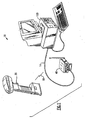
- FIG. 1 An exemplary embodiment of the data collection network of the present invention is shown in Figure 1 , and is designated generally throughout by reference numeral 10.
- the present invention for a data collection network includes a cordless optical scanner 20 for reading a 2D optically encoded symbol.
- the optical scanner converts the 2D optically encoded symbol into decoded data.
- the optical scanner includes a packet assembly component operative to convert the decoded data into a plurality of packets.
- a communications component transmits the packets to a base terminal.
- the present invention provides a data collection network that accommodates 2D data codes containing large amounts of data.
- the data collection network of the present invention provides users with the data transmission capacity required to perform increasingly complex data collection tasks in an untethered working environment.
- Data collection network 10 includes N-cordless optical scanners 20 coupled to base terminal 40 by means of radio link 16.
- Base terminal 40 is connected to host computer 100 by communications link 14.
- the optical scanner is a portable self-contained hand-held unit that is capable of scanning and decoding optically encoded symbols.
- the host computer 100 is provided by the user to further process data collected by base terminal 40.
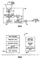
- Cordless scanner 20 includes scan assembly 22, which is connected to processor 24.
- Processor 24 is connected to memory 26 and I/O port 28.
- I/O port 28 is connected to radio controller 30.
- Radio controller 30 is likewise connected to antenna 32.
- Scan assembly 22 includes a light source and optics to illuminate the optical symbol. Reflected light returning from the optical symbol is captured by a photodetector element and converted into analog electrical signals representative of the optical symbol. Scan assembly 22 also includes signal processing electronics that digitize the analog signals. It will be apparent to those of ordinary skill in the pertinent art that modifications and variations can be made to scan assembly 22 of the present invention depending on cost and component selection. For example, scan assembly 22 may be image sensor based or laser based. Further, scan assembly 22 may be a linear scanner or an area scanner. A linear scanner captures one row of the 2D symbol at a time, whereas an area scanner captures an image of the entire 2D symbol with one scan.
- processor 24 may be of any suitable type, but by way of example, processor 24 includes an 8-bit microcomputer having an address space 64K bytes. Processor 24 uses the firmware stored in memory 26 to perform the various tasks necessary to operate scanner 20. Processor 24 may also include an ASIC device to manage and optimize scan assembly 22 operations. The firmware resident in the memory 26 includes decoding component and a packet assembly component. The structure of memory 26 will be discussed below.
- the communications component of optical scanner 20 includes radio controller 30. It will be apparent to those of ordinary skill in the pertinent art that radio controller 30 may be of any suitable type, but by way of example, radio controller 30 is adapted to provide frequency hopping spread spectrum communications (FHSS) between scanner 20 and base terminal 40.
- FHSS frequency hopping spread spectrum communications
- FHSS is a form of spread spectrum radio transmission that produces a narrow band signal that hops among a plurality of frequencies in a prearranged pattern.
- FHSS is often used in commercial environments because of its ability to minimize errors due to interference or jamming.
- optical scanners 20 and base terminal 40 may communicate using other wireless schemes and other modulation formats based on user requirements and environmental factors.
- Memory 26 includes read only memory 260 for storing optical scanner firmware.
- Memory 260 may be of any suitable type, but there is shown by way of example a 32K Byte erasable programmable read only memory (EPROM) 260.
- EPROM erasable programmable read only memory
- Memory 260 includes a main program, a parameter table, decoding routine, packet assembly routine, and other miscellaneous routines that run on processor 24.
- Memory 26 also includes data storage memory 262.
- Memory 262 may be of any suitable type, but there is shown by way of example 8K Bytes SRAM which is used by processor 24 for data storage. One portion of memory is used to store digitized scan data. Another portion is used to store the decoded data.
- the parameter table specifies the values of the parameters defining the mode in which the reader will operate. Examples of these parameters include the size and the frame rate of the scan assembly image sensor, the codes that will be enabled during autodiscrimination, communication protocols, beeper pitch and volume. As will be discussed more fully below, the subset of parameter values populating the scanner parameter table are chosen in accordance with the selected application. A complete set of application parameters are stored in base terminal 40 memory. Base terminal 40 uploads the subset of parameter values to scanner 20.
- the decoding routine is also stored in firmware. It uses parameters stored in the parameter table. Thus, the decoding routine can be modified by these parameters to decode any number of 2D optical symbols such as PDF 417, microPDF, Code One, DataMatrix or MaxiCode.
- the present invention also applies to stacked linear symbols and matrix symbols. This list is not all-inclusive. Any type of symbol can be used in conjunction with network 10.
- the firmware operates on a PDF417 symbol according to a two step process.
- the first step of the process is row decoding. This step includes locating sequences of PDF417 symbol characters adjoining a stop or start character. This process is complicated by a phenomenon known as scan-stitching wherein the scan path slides from row to row generating invalid characters.
- the decoding process takes advantage of the fact that all characters start with a space-to-bar transition that is aligned across rows.
- the second step of the decoding process is array decoding.
- array decoding the decoded PDF417 characters are placed into appropriate positions in a row and column matrix. These rows are then considered as one concatenated string which is error checked and corrected to generate the decoded data message.
- each packet can accommodate approximately 200 bytes of decoded data in a 256 byte packet. This is merely a representative example, and one of ordinary skill in the art will recognize that the scope of the present invention should not be limited to data packets of a certain size or format.
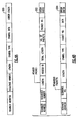
- FIG. 4A is a diagrammatic depiction of a data packet used to transmit decoded data from an optical scanner to a base terminal when only one data packet is required.
- a one packet message employs packet 200 which includes a scanner address field, sequence number field, a packet length field, a symbol type field, symbol data, and an error check field.
- the scanner address is a scanner identifier.
- Each scanner 20 numbers each packet with a sequence number, which is includes in the second field.
- the next field contains the length of the data field. After this, the packet contains a field identifying the type of symbol that was decoded. After the symbol type, the symbol data payload of the packet is inserted.
- packet 200 includes error checking bytes.
- Figure 4B is a diagrammatic depiction of a header packet and a data packet used to transmit decoded data from an optical scanner to a base terminal when more than one data packet is required.
- scanner 20 first transmits header packet 202. After base 40 acknowledges that it can process the remaining packets, scanner 20 transmits the remaining packets 204, which have the format of packet 204. If base 40 cannot process the remaining packets 204, or if there is another problem, base 40 will transmit an application packet to scanner 20 indicating the error.
- the definitions of the scanner address field, the sequence number field, symbol type, length, symbol data, and error check field were described above, and hence, will not be repeated.
- Header packet 202 also includes a header identification field, which identifies the packet as a header packet.
- packet 202 includes a total length field, which includes the total length of the data contained in the decoded symbol.
- the next field includes the total number of packets in the message.
- the second-last field is the packet number. In the header packet, this number is designated as packet number "one.”
- the remaining packets 204 also include a packet number field, which are incremented from 2 to N, depending on the total number of packets being transmitted in the message.
- packet 200, packet 202, and packet 204 may be of any suitable type
- the diagrammatic depictions in Figure 4A and Figure 4B are one embodiment of the present invention.
- the headers and field type can be implemented in a variety of ways.
- an exemplary optical scanner flow chart 300 according to the present invention is disclosed.
- step 302 the optical symbol is read.
- the image is captured and stored in memory 262 as digitized scan data.
- the digitized scan data is decoded in step 304, in accordance with the application being run on scanner 20.
- a PDF417 decoding process was discussed above. It will be apparent to those of ordinary skill in the pertinent art that microPDF, Code One, DataMatrix, MaxiCode or any other 2D symbol can also be decoded when practicing the present invention.
- processor 24 determines whether the symbol is an application selector symbol. Application selector symbols are used to reprogram scanner 20.
- step 316 base terminal 40 retrieves the corresponding parameter table subset and uploads it into scanner 20.
- step 318 scanner 20 stores the new parameter table information in memory 260 or 262.
- Scanner 20 is equipped with a reprogramming routine in firmware which causes scanner 20 to operate in accordance with the new up-loaded parameter table values.
- the scanner proceeds to block 308.
- the concatenated decoded data string is broken into decoded data payloads of approximately 200 bytes each. Of course, the last decoded data payload may only have a few bytes of data, depending on the message size.
- Block 308 generates headers 202 for each of the packets in the message. Subsequently, a payload is appended to its corresponding header.
- each packet is sent to radio controller 30 via I/O port 28. Radio controller 30 transmits each packet to base terminal 40 until the entire message has been transmitted, in accordance with block 312.
- Base terminal 40 transmits and receives messages from optical scanners 20 via antenna 42.
- Antenna 42 is connected to radio controller 44.
- Radio controller 44 is coupled to base terminal 48 via I/O port 46.
- Base terminal processor 48 is also connected to base terminal memory 50.
- Base terminal 40 also includes a second I/O port 52 that links processor 48 with host 100 via communications link 14.
- radio controller 44 may be of any suitable type, but by way of example, radio controller 44 is adapted to provide frequency hopping spread spectrum communications (FHSS) between scanner 20 and base terminal 40.
- FHSS frequency hopping spread spectrum communications
- optical scanners 20 and base terminal 40 may communicate using other wireless schemes and other modulation formats based on user requirements and environmental factors.
- Base terminal processor 48 may be of any suitable type adapted to facilitate contemporaneous execution of a plurality of applications.
- Each scanner 20 in network 10 may operate according to any number of applications.
- Each application may specify different data collection protocols, e.g., one scanner may be programmed to decode PDF417 whereas another may be programmed to decoded Code One symbols and read at different data rates.
- base 40 is adapted to interface with a plurality of scanners 20 transmitting a plurality of packets. The packets received from scanners 20 are interlaced and appropriately sorted by base 40. The operation of base terminal 40 will be discussed below in conjunction with Figure 10 .
- communications link 100 may be of any suitable type, but by way of example, base terminal 40 may be hard wired to host 100 via an RS-232 communications link.
- Link 14 may also be implemented using a "wedge" terminal disposed between base terminal 40 and host 100. In other embodiments, link 14 may be implemented using a LAN, or a universal serial bus.
- Host computer 100 may include at least one high level data processing software program such as a graphical display program, a spreadsheet program, or word processing program for arranging, displaying and/or organizing the decoded data in accordance with the user's needs and requirements.
- a high level data processing software program such as a graphical display program, a spreadsheet program, or word processing program for arranging, displaying and/or organizing the decoded data in accordance with the user's needs and requirements.
- Memory 50 includes erasable programmable read only memory (EPROM) 500, which is used for storing the base terminal firmware.
- EPROM erasable programmable read only memory
- Memory 500 includes a base terminal main program, a packet interpretation and disassembly routine, a scanner-application look-up table, an application-parameter look-up table, and other miscellaneous routines that run on processor 48.
- Memory 50 also includes data storage memory 502.
- Memory 502 may be of any suitable type, but there is shown by way of example a SRAM which is used by processor 48 for data storage.
- LUT 600 correlates each scanner 20 in network 10 with the current application of each scanner 20 using suitable addressing identifiers.
- LUT 600 can be stored in any memory structure in network 10, but it is preferably stored in base terminal memory 50.
- Figure 9 is a diagram showing the structure of an application-parameter look-up table 700 disposed in memory 500 of base terminal 40.
- Application parameter table 700 correlates each application with the parameters needed to control the various aspects of network operations. Further, application-parameter table 700 includes the plurality of parameters used to control symbology, scanning, decoding, and communications in optical scanners 20 for all of the applications supported by network 10.
- base terminal 40 reads the packet transmitted by scanner 20.
- Base terminal 40 determines in block 804 whether the packet contains an application selector symbol request, or decoded data. If the packet is an application selector packet, base terminal 40 retrieves the parameter table subset corresponding to the requested application from LUT 700 ( Figure 9 ), and changes the scanner-application LUT 600 accordingly. These actions are performed by blocks 806-808. If the packet is not an application selector packet, block 810 is performed and the remainder of the packet header is read.
- base terminal 40 identifies the scanner 20 from which the packet was sent, the current application being run on scanner 20, the message number, the number of packets in the message, and the number of the packet being evaluated. Using this information, the decoded data payload is stored in an appropriate place in data storage memory 502.
- base terminal processor 48 determines whether all the packets in the message were received. If not, the processor waits for additional packets to be received. If all packets have been received, processor 48 assembles all of the decoded data payloads into a concatenated data string. Of course, the concatenated data string includes all of the data stored in the 2D optical symbol decoded by scanner 20.
- base terminal 40 transmits the decoded data to host 100 via communications link 14.
Landscapes
- Engineering & Computer Science (AREA)
- Physics & Mathematics (AREA)
- Electromagnetism (AREA)
- Health & Medical Sciences (AREA)
- General Health & Medical Sciences (AREA)
- Theoretical Computer Science (AREA)
- General Physics & Mathematics (AREA)
- Computer Networks & Wireless Communication (AREA)
- Signal Processing (AREA)
- Computing Systems (AREA)
- General Engineering & Computer Science (AREA)
- Medical Informatics (AREA)
- Computer Security & Cryptography (AREA)
- Toxicology (AREA)
- Artificial Intelligence (AREA)
- Computer Vision & Pattern Recognition (AREA)
- Optical Communication System (AREA)
- Telephonic Communication Services (AREA)
- Data Exchanges In Wide-Area Networks (AREA)
- Small-Scale Networks (AREA)
Abstract
Description
- The present invention relates generally to data collection networks, and particularly to data collection networks that employ optical scanners as data input terminals.
- Data collection networks that use optical bar code scanners as input terminals are being employed in an ever-expanding variety of work environments. Examples of such network applications include retail, shipping, work-in-progress tracking, inventory control, manufacturing, route accounting, and health care. The sophistication of the networks and bar code scanners have grown markedly to keep pace with this demand.
- One area of sophistication relates to wireless networks. The demand for cordless optical scanners operating in a wireless environment is increasing. Many of the new optical scanner applications require freedom of movement. The presence of an electrical cord tethering the optical scanner to a base terminal can be very problematic. In manufacturing or industrial applications, the cord may become entangled in assembly lines or in other machinery having moving parts.
- The cordless optical scanners currently on the market have the capability to read optical symbols having limited data capacity. The scanner reads the symbol and refers to a look-up table in memory to retrieve the information corresponding to the symbol. 2D optical codes have been developed to carry large amounts of information, obviating the need for scanners to perform code conversions using look-up tables. Portable data file optical codes, for example, have maximum data capacities exceeding 1,000 bytes of information. PDF 417 can accommodate 2710 digits of information. Code One has a maximum data capacity of 1478 bytes. DataMatrix and MaxiCode symbols have similar data capacities. Unfortunately, currently available cordless optical scanners, and the data collection networks employing them, do not have the data transmission capabilities required to accommodate these large data codes.
-
US ,142,550 which is regarded as closest prior art document, discloses a packet data transmission system which is used to link a number of remote hand-held data-gathering units such as bar code readers to a central computer which maintains a data base management system. Data packets are sent from the remote units by an RF link to intermediate base stations, then sent by the base stations to the central computer by a serial link. Direct sequence spread spectrum modulation is used for the RF link. The remote hand-held units initiate an exchange using RF transmission to and from the base stations, receiving only during a rigid time window following a transmission from the remote unit. The base stations cannot initiate communication to the remote units, but instead send data to the remote units only as part of the exchange. - Thus, there is a need for an optical scanner data collection network that can accommodate 2 D data codes containing large amounts of information. A data collection network is needed to provide users with the data capacity required to perform increasingly complex tasks in an untethered working environment.
- The above problem is solved by a data collection network according to
independent claim 1 and a method for transmitting information contained in an optical symbol using a wireless network according to independent claim 43. Additional modifications and further developments of the present invention are derivable from the specification, the drawings and the dependent claims. - The existing problems of conventional optical scanners and data collection networks are addressed by the present invention. The present invention relates to multi-packet transmission of decoded data using RF scanners. The present invention also provides a data collection network that can accommodate 2D data codes containing large amounts of information. The data collection network of the present invention provides users with the data transmission capacity required to perform increasingly complex tasks in an untethered working environment.
- One aspect of the present invention is a cordless optical scanner for reading a 2D optically encoded symbol. The optical scanner converts the 2D optically encoded symbol into decoded data. The optical scanner includes a packet assembly component operative to convert the decoded data into a plurality of packets. A communications component is coupled to the packet assembly component. The communications component is operative to transmit the plurality of packets to a base terminal.
- In another aspect, the present invention includes a data collection network having at least one cordless optical scanner. The optical scanner is operative to convert a 2D optical symbol into a plurality of data packets for transmission over an RF channel. A base terminal is coupled to the at least one cordless optical scanner via the RF channel. The base terminal is operative to reassemble the plurality of packets into decoded data.
- In another aspect, the present invention includes a method for transmitting information contained in a 2D optical symbol using a wireless network. The wireless network includes at least one cordless optical scanner and a base terminal. The method includes reading the 2D optical symbol with the cordless optical scanner to thereby generate decoded data. The decoded data is assembled into a plurality of packets. At least one packet of the plurality of packets includes at least 200 bytes of decoded data. The plurality of packets are transferred from the cordless optical scanner to the base terminal over an RF channel. The received plurality of packets are converted into the decoded data.
- Additional features and advantages of the invention will be set forth in the detailed description which follows, and in part will be readily apparent to those skilled in the art from that description or recognized by practicing the invention as described herein, including the detailed description which follows, the claims, as well as the appended drawings.
- It is to be understood that both the foregoing general description and the following detailed description are merely exemplary of the invention, and are intended to provide an overview or framework for understanding the nature and character of the invention as it is claimed. The accompanying drawings are included to provide a further understanding of the invention, and are incorporated in and constitute a part of this specification. The drawings illustrate various embodiments of the invention, and together with the description serve to explain the principles and operation of the invention.
-
-
Figure 1 is a perspective view of the optical scanner data collection network according to the present invention; -
Figure 2 is a block diagram of the optical scanner according to the present invention; -
Figure 3 is a diagram representing the memory map of the optical scanner according to the present invention; -
Figure 4A is a diagrammatic depiction of a data packet used to transmit decoded data from an optical scanner to a base terminal when only one data packet is required; -
Figure 4B is a diagrammatic depiction of a header packet and a data packet used to transmit decoded data from an optical scanner to a base terminal when more than one data packet is required; -
Figure 5 is an exemplary optical scanner flow chart according to the present invention; -
Figure 6 is a block diagram of the base terminal according to the present invention; -
Figure 7 is a diagram representing the memory map ofbase terminal 40 according to the present invention; -
Figure 8 is a diagram showing the structure of a scanner-application look-up table disposed in the memory of the base terminal; -
Figure 9 is a chart showing the structure of an application-parameter look-up table disposed in the memory of the base terminal; and -
Figure 10 is an exemplary base terminal flow chart according to the present invention. - Reference will now be made in detail to the present preferred embodiments of the invention, examples of which are illustrated in the accompanying drawings. Wherever possible, the same reference numbers will be used throughout the drawings to refer to the same or like parts. An exemplary embodiment of the data collection network of the present invention is shown in
Figure 1 , and is designated generally throughout byreference numeral 10. - In accordance with the invention, the present invention for a data collection network includes a cordless
optical scanner 20 for reading a 2D optically encoded symbol. The optical scanner converts the 2D optically encoded symbol into decoded data. The optical scanner includes a packet assembly component operative to convert the decoded data into a plurality of packets. A communications component transmits the packets to a base terminal. The present invention provides a data collection network that accommodates 2D data codes containing large amounts of data. The data collection network of the present invention provides users with the data transmission capacity required to perform increasingly complex data collection tasks in an untethered working environment. - As embodied herein, and depicted in
Figure 1 , a perspective view of the optical scannerdata collection network 10 according to the present invention is shown.Data collection network 10 includes N-cordlessoptical scanners 20 coupled tobase terminal 40 by means ofradio link 16.Base terminal 40 is connected tohost computer 100 by communications link 14. As shown, the optical scanner is a portable self-contained hand-held unit that is capable of scanning and decoding optically encoded symbols. Typically thehost computer 100 is provided by the user to further process data collected bybase terminal 40. - As embodied herein and depicted in
Figure 2 , a block diagram of theoptical scanner 20 according to the present invention is shown.Cordless scanner 20 includesscan assembly 22, which is connected toprocessor 24.Processor 24 is connected tomemory 26 and I/O port 28. I/O port 28 is connected toradio controller 30.Radio controller 30 is likewise connected toantenna 32. -
Scan assembly 22 includes a light source and optics to illuminate the optical symbol. Reflected light returning from the optical symbol is captured by a photodetector element and converted into analog electrical signals representative of the optical symbol.Scan assembly 22 also includes signal processing electronics that digitize the analog signals. It will be apparent to those of ordinary skill in the pertinent art that modifications and variations can be made to scanassembly 22 of the present invention depending on cost and component selection. For example, scanassembly 22 may be image sensor based or laser based. Further, scanassembly 22 may be a linear scanner or an area scanner. A linear scanner captures one row of the 2D symbol at a time, whereas an area scanner captures an image of the entire 2D symbol with one scan. - It will be apparent to those of ordinary skill in the pertinent art that
processor 24 may be of any suitable type, but by way of example,processor 24 includes an 8-bit microcomputer having an address space 64K bytes.Processor 24 uses the firmware stored inmemory 26 to perform the various tasks necessary to operatescanner 20.Processor 24 may also include an ASIC device to manage and optimizescan assembly 22 operations. The firmware resident in thememory 26 includes decoding component and a packet assembly component. The structure ofmemory 26 will be discussed below. - The communications component of
optical scanner 20 includesradio controller 30. It will be apparent to those of ordinary skill in the pertinent art thatradio controller 30 may be of any suitable type, but by way of example,radio controller 30 is adapted to provide frequency hopping spread spectrum communications (FHSS) betweenscanner 20 andbase terminal 40. FHSS is a form of spread spectrum radio transmission that produces a narrow band signal that hops among a plurality of frequencies in a prearranged pattern. FHSS is often used in commercial environments because of its ability to minimize errors due to interference or jamming. However, those of ordinary skill in the art will recognize thatoptical scanners 20 andbase terminal 40 may communicate using other wireless schemes and other modulation formats based on user requirements and environmental factors. - As embodied herein and depicted in
Figure 3 , a diagram representing the memory map of the optical scanner according to the present invention is shown.Memory 26 includes read onlymemory 260 for storing optical scanner firmware.Memory 260 may be of any suitable type, but there is shown by way of example a 32K Byte erasable programmable read only memory (EPROM) 260.Memory 260 includes a main program, a parameter table, decoding routine, packet assembly routine, and other miscellaneous routines that run onprocessor 24.
Memory 26 also includesdata storage memory 262.Memory 262 may be of any suitable type, but there is shown by way of example 8K Bytes SRAM which is used byprocessor 24 for data storage. One portion of memory is used to store digitized scan data. Another portion is used to store the decoded data. - Referring back to
memory 260, the parameter table specifies the values of the parameters defining the mode in which the reader will operate. Examples of these parameters include the size and the frame rate of the scan assembly image sensor, the codes that will be enabled during autodiscrimination, communication protocols, beeper pitch and volume. As will be discussed more fully below, the subset of parameter values populating the scanner parameter table are chosen in accordance with the selected application. A complete set of application parameters are stored inbase terminal 40 memory.Base terminal 40 uploads the subset of parameter values toscanner 20. - The decoding routine is also stored in firmware. It uses parameters stored in the parameter table. Thus, the decoding routine can be modified by these parameters to decode any number of 2D optical symbols such as PDF 417, microPDF, Code One, DataMatrix or MaxiCode. The present invention also applies to stacked linear symbols and matrix symbols. This list is not all-inclusive. Any type of symbol can be used in conjunction with
network 10. - By way of example, the decoding routine for PDF417 symbols will be discussed. The firmware operates on a PDF417 symbol according to a two step process. The first step of the process is row decoding. This step includes locating sequences of PDF417 symbol characters adjoining a stop or start character. This process is complicated by a phenomenon known as scan-stitching wherein the scan path slides from row to row generating invalid characters. The decoding process takes advantage of the fact that all characters start with a space-to-bar transition that is aligned across rows.
- The second step of the decoding process is array decoding. In array decoding, the decoded PDF417 characters are placed into appropriate positions in a row and column matrix. These rows are then considered as one concatenated string which is error checked and corrected to generate the decoded data message.
- Subsequently, the decoded data message is assembled into one or more packets, depending on the length of the data embedded in the decoded symbol. This step is performed by the packet assembly routine. In one embodiment of the present invention, each packet can accommodate approximately 200 bytes of decoded data in a 256 byte packet. This is merely a representative example, and one of ordinary skill in the art will recognize that the scope of the present invention should not be limited to data packets of a certain size or format.
-
Figure 4A is a diagrammatic depiction of a data packet used to transmit decoded data from an optical scanner to a base terminal when only one data packet is required. A one packet message employspacket 200 which includes a scanner address field, sequence number field, a packet length field, a symbol type field, symbol data, and an error check field. The scanner address is a scanner identifier. Eachscanner 20 numbers each packet with a sequence number, which is includes in the second field. The next field contains the length of the data field. After this, the packet contains a field identifying the type of symbol that was decoded. After the symbol type, the symbol data payload of the packet is inserted. Finally,packet 200 includes error checking bytes. -
Figure 4B is a diagrammatic depiction of a header packet and a data packet used to transmit decoded data from an optical scanner to a base terminal when more than one data packet is required. When more than one packet is required,scanner 20 firsttransmits header packet 202. Afterbase 40 acknowledges that it can process the remaining packets,scanner 20 transmits the remainingpackets 204, which have the format ofpacket 204. Ifbase 40 cannot process the remainingpackets 204, or if there is another problem,base 40 will transmit an application packet toscanner 20 indicating the error. The definitions of the scanner address field, the sequence number field, symbol type, length, symbol data, and error check field were described above, and hence, will not be repeated.Header packet 202 also includes a header identification field, which identifies the packet as a header packet. In the next field,packet 202 includes a total length field, which includes the total length of the data contained in the decoded symbol. The next field includes the total number of packets in the message. The second-last field is the packet number. In the header packet, this number is designated as packet number "one." The remainingpackets 204 also include a packet number field, which are incremented from 2 to N, depending on the total number of packets being transmitted in the message. - One of ordinary skill in the art will recognize that
packet 200,packet 202, andpacket 204 may be of any suitable type, the diagrammatic depictions inFigure 4A and Figure 4B are one embodiment of the present invention. The headers and field type can be implemented in a variety of ways. - As embodied herein and depicted in
Figure 5 , an exemplary optical scanner flow chart 300 according to the present invention is disclosed. Instep 302 the optical symbol is read. As discussed above, the image is captured and stored inmemory 262 as digitized scan data. The digitized scan data is decoded instep 304, in accordance with the application being run onscanner 20. A PDF417 decoding process was discussed above. It will be apparent to those of ordinary skill in the pertinent art that microPDF, Code One, DataMatrix, MaxiCode or any other 2D symbol can also be decoded when practicing the present invention. After the symbol is decoded,processor 24 determines whether the symbol is an application selector symbol. Application selector symbols are used to reprogramscanner 20. If the symbol is an application selector symbol, a single packet containing the application selection information is sent to base terminal 40 instep 314. Instep 316,base terminal 40 retrieves the corresponding parameter table subset and uploads it intoscanner 20. Instep 318,scanner 20 stores the new parameter table information inmemory Scanner 20 is equipped with a reprogramming routine in firmware which causesscanner 20 to operate in accordance with the new up-loaded parameter table values. - If the decoded symbol is not an application selector symbol, the scanner proceeds to block 308. The concatenated decoded data string is broken into decoded data payloads of approximately 200 bytes each. Of course, the last decoded data payload may only have a few bytes of data, depending on the message size.
Block 308 generatesheaders 202 for each of the packets in the message. Subsequently, a payload is appended to its corresponding header. Inblock 310, each packet is sent toradio controller 30 via I/O port 28.Radio controller 30 transmits each packet tobase terminal 40 until the entire message has been transmitted, in accordance withblock 312. - As embodied herein and depicted in
Figure 6 , a block diagram ofbase terminal 40 according to the present invention is depicted.Base terminal 40 transmits and receives messages fromoptical scanners 20 viaantenna 42.Antenna 42 is connected toradio controller 44.Radio controller 44 is coupled tobase terminal 48 via I/O port 46.Base terminal processor 48 is also connected to baseterminal memory 50.Base terminal 40 also includes a second I/O port 52 that linksprocessor 48 withhost 100 via communications link 14. - As discussed above in conjunction with
radio controller 30 ofoptical scanner 20, it will be apparent to those of ordinary skill in the pertinent art thatradio controller 44 may be of any suitable type, but by way of example,radio controller 44 is adapted to provide frequency hopping spread spectrum communications (FHSS) betweenscanner 20 andbase terminal 40. Again, those of ordinary skill in the art will recognize thatoptical scanners 20 andbase terminal 40 may communicate using other wireless schemes and other modulation formats based on user requirements and environmental factors. -
Base terminal processor 48 may be of any suitable type adapted to facilitate contemporaneous execution of a plurality of applications. Eachscanner 20 innetwork 10 may operate according to any number of applications. Each application may specify different data collection protocols, e.g., one scanner may be programmed to decode PDF417 whereas another may be programmed to decoded Code One symbols and read at different data rates. Thus,base 40 is adapted to interface with a plurality ofscanners 20 transmitting a plurality of packets. The packets received fromscanners 20 are interlaced and appropriately sorted bybase 40. The operation ofbase terminal 40 will be discussed below in conjunction withFigure 10 . - As any skilled artisan will recognize, communications link 100 may be of any suitable type, but by way of example,
base terminal 40 may be hard wired to host 100 via an RS-232 communications link.Link 14 may also be implemented using a "wedge" terminal disposed betweenbase terminal 40 andhost 100. In other embodiments, link 14 may be implemented using a LAN, or a universal serial bus. -
Host computer 100 may include at least one high level data processing software program such as a graphical display program, a spreadsheet program, or word processing program for arranging, displaying and/or organizing the decoded data in accordance with the user's needs and requirements. - As embodied herein and depicted in
Figure 7 , a diagram representing the memory map ofbase terminal 40 according to the present invention is shown.Memory 50 includes erasable programmable read only memory (EPROM) 500, which is used for storing the base terminal firmware.Memory 500 includes a base terminal main program, a packet interpretation and disassembly routine, a scanner-application look-up table, an application-parameter look-up table, and other miscellaneous routines that run onprocessor 48. -
Memory 50 also includesdata storage memory 502.Memory 502 may be of any suitable type, but there is shown by way of example a SRAM which is used byprocessor 48 for data storage. - As embodied herein and depicted in
Figure 8 , a diagram showing the structure of a scanner-application look-up table 600 disposed inmemory 500 is shown.Network 10 may include N-optical scanners 20. Theoretically, there can be an infinite number applications. Look-up-table (LUT) 600 correlates eachscanner 20 innetwork 10 with the current application of eachscanner 20 using suitable addressing identifiers.LUT 600 can be stored in any memory structure innetwork 10, but it is preferably stored inbase terminal memory 50. -
Figure 9 is a diagram showing the structure of an application-parameter look-up table 700 disposed inmemory 500 ofbase terminal 40. Application parameter table 700 correlates each application with the parameters needed to control the various aspects of network operations. Further, application-parameter table 700 includes the plurality of parameters used to control symbology, scanning, decoding, and communications inoptical scanners 20 for all of the applications supported bynetwork 10. - As embodied herein and depicted in
Figure 10 , an exemplary base terminal flow chart according to the present invention is depicted. Inblock 802,base terminal 40 reads the packet transmitted byscanner 20.Base terminal 40 determines inblock 804 whether the packet contains an application selector symbol request, or decoded data. If the packet is an application selector packet,base terminal 40 retrieves the parameter table subset corresponding to the requested application from LUT 700 (Figure 9 ), and changes the scanner-application LUT 600 accordingly. These actions are performed by blocks 806-808. If the packet is not an application selector packet, block 810 is performed and the remainder of the packet header is read. Thus,base terminal 40 identifies thescanner 20 from which the packet was sent, the current application being run onscanner 20, the message number, the number of packets in the message, and the number of the packet being evaluated. Using this information, the decoded data payload is stored in an appropriate place indata storage memory 502. Inblock 814,base terminal processor 48 determines whether all the packets in the message were received. If not, the processor waits for additional packets to be received. If all packets have been received,processor 48 assembles all of the decoded data payloads into a concatenated data string. Of course, the concatenated data string includes all of the data stored in the 2D optical symbol decoded byscanner 20. Inblock 818,base terminal 40 transmits the decoded data to host 100 via communications link 14. - It will be apparent to those skilled in the art that various modifications and variations can be made to the present invention without departing from the scope of the claims. Thus, it is intended that the present invention cover the modifications and variations of this invention provided they come within the scope of the appended claims.
Claims (43)
- A data collection network comprising:a plurality of cordless optical scanners (20), anda base terminal (40) with an application parameter look-up table (700) stored therein, the look-up table storing application parameters for each of the plurality of the cordless optical scanners; wherein
at least one scanner of the plurality of cordless optical scanners (20) is configured to convert a 2D optical symbol into decoded data, and
to format the decoded data into a plurality of packets (202, 204),
the at least one scanner of the plurality of cordless optical scanners (20) is further configured to transmit a first packet (202) of the plurality of packets (202, 204) over a radio frequency channel (16) to the base terminal (40), and
the base terminal (40) is coupled to the at least one of the plurality of cordless optical scanners (20) over the radio frequency channel (16); and wherein
the base terminal (40) is operative to receive and reassemble the plurality of packets (202, 204) into decoded data, the data collection network being characterized in that
the first packet (202) of the plurality of packets (202, 204) contains a field designating the total length of the decoded data, and
the at least one scanner is further configurated to transmit an at least one second packet of the plurality of packets (202, 204) responsively to receiving an acknowledgment from the base terminal (40), the acknowledgment confirming the ability of the base terminal (40) to process the at least one second packet (204) of the plurality of packets (202, 204). - The data collection network of claim 1, wherein the base terminal (40) is configured to contemporaneously communicate with each of the plurality of optical scanners (20, 600).
- The data collection network of claim 2, wherein application parameters include a type of 2D optical symbol being decoded by each of the plurality of optical scanners (20, 600).
- The data collection network of claim 3, wherein the type of 2D optical symbol being decoded by the optical scanner (20, 600) is a portable data file symbol (PDF).
- The optical scanner (20, 600) of claim 3, wherein the type of 2D optical symbol being decoded by the optical scanner (20, 600) is a PDF 417 symbol.
- The optical scanner (20, 600) of claim 4, wherein the type of 2D optical symbol being decoded by the optical scanner (20, 600) is a micro PDF symbol.
- The optical scanner (20, 600) of claim 3, wherein the type of 2D optical symbol being decoded by the optical scanner (20, 600) is a Code One symbol.
- The optical scanner (20, 600) of claim 3, wherein the type of 2D optical symbol being decoded by the optical scanner (20, 600) is a DataMatrix symbol.
- The optical scanner (20, 600) of claim 3, wherein the type of 2D optical symbol being decoded by the optical scanner (20, 600) is a MaxiCode symbol.
- The data collection network of claim 2, wherein application parameters include transmission protocol data.
- The data collection network of claim 2, wherein application parameters include optical scanner (20, 600) scanning rate data.
- The data collection network of claim 2, wherein the base terminal (40) further comprises:a base communications component (44) operative to receive the transmitted plurality of packets from the plurality of optical scanners (20, 600);a base processor (48) coupled to the base communications component (44), the base processor (48) programmed to process the received plurality of packets (202, 204) to thereby recover the decoded data; anda first base memory (50) coupled to the base processor (48), the first base memory (50) being operative to store the decoded data.
- The data collection network of claim 12, wherein the base processor (48) further comprises:a packet interpreter component (50), the interpreter component (50) operative to read at least one informational field of the packet, whereby the plurality of packets (202, 204) is processed in accordance with information retrieved from the at least one informational field,a packet disassembler portion coupled to the packet interpreter component (50), the packet disassembler being operative to recover the decoded data portion; anda message assembler coupled to the packet disassembler, the message assembler being operative to assemble the decoded data portion of each packet to thereby produce the decoded data.
- The data collection network of claim 12, wherein the base communications component (44) further comprises:a transmitter component adapted to upload control data to the plurality of optical scanners (20, 600); anda receiver component adapted to receive the plurality of packets (202, 204) from the plurality of optical scanners (20, 600).
- The data collection network of claim 1, further comprising a host computer (100) coupled to the base terminal (40), the host computer (100) being adapted to further process the decoded data.
- The data collection network of claim 15, wherein the host computer (100) is coupled to the base terminal (40) by means of an RS-232 data link (14).
- The data collection network of claim 15, wherein the host computer (100) is coupled to the base terminal (40) by means of a wedge terminal.
- The data collection network of claim 15, wherein the host computer (100) is coupled to the base terminal (40) by means of a local area network (LAN) (14).
- The data collection network of claim 15, wherein the host computer (100) is coupled to the base terminal (40) by means of a universal serial bus (14).
- The data collection network of claim 1, where each of the plurality of packets (202, 204) includes a data structure including:a first field including an optical scanner (20, 600) identifier, the optical scanner (20, 600) identifier identifying an optical scanner (20, 600);a second field including an optical symbol identifier (200), the optical symbol identifier (200) identifying a type of optical symbol being decoded by the optical scanner (20, 600); anda third field including error checking information (200), the error checking information (200) enabling a receiving base station (40) to check a received message for errors.
- The data collection network of claim 20, wherein the data structure is included within a header packet (202) adapted to a multiple packet transmission format.
- The data collection network of claim 21, wherein the data structure is included within a non-header packet (204) adapted to a multiple packet transmission format.
- The data collection network of claim 20, wherein the data structure is included within a packet (202) adapted to a single packet transmission format.
- The data collection network of claim 20, wherein the data structure includes a fourth field for containing symbol data (200), the symbol data (200) representing data contained in an optical symbol of the type identified by the optical symbol identifier (200).
- The data collection network of claim 1 where the plurality of optical scanners (20, 600) comprises:a packet assembly component operative to convert the decoded data into at least one packet; anda communications component (30) coupled to the packet assembly component, the communications component being operative to transmit the plurality of packets (202, 204) to a base terminal (40).
- The data collection network of claim 25, wherein the plurality of packets (202, 204) includes a header packet (202).
- The data collection network of claim 26, wherein the header packet (202) includes decoded data if a transmission to the base terminal (40) includes only one packet.
- The data collection network of claim 27, wherein the header packet includes at least an optical scanner identifier (200), a length of the decoded data, and error checking information (200).
- The data collection network of claim 26, wherein the plurality of packets (202, 204) includes a non-header packet (204).
- The data collection network of claim 29, wherein the non-header packet (204) includes a field identifying a type of 2D optically encoded symbol being read by the optical scanner (20, 600).
- The data collection network of claim 30, wherein the 2D optically encoded symbol includes stacked linear symbols and matrix symbols.
- The data collection network of claim 25, where the optical scanner (20, 600) further comprises:a scan assembly (22) operative to read the 2D optically encoded symbol, whereby the symbol is converted into an electrical signal; anda decoding component (26) coupled to the scan assembly and the packet assembly component (26), the decoding component converting the electrical signal into the decoded data.
- The data collection network of claim 32, wherein the scan assembly (22) is a linear scan assembly.
- The data collection network of claim 32, wherein the scan assembly is an area scan assembly.
- The data collection network of claim 25, where the optical scanner (20, 600) further comprises:a scan assembly operative to read the 2D optically encoded symbol, whereby the 2D optically encoded symbol is converted into an electrical signal;a processor (24) coupled to the scan assembly (22), the processor being programmed to decode the electrical signal to thereby produce decoded data, assemble the decoded data into a plurality of packets (202, 204);a modulator coupled to the processor, the modulator being operative to modulate the plurality of packets (202, 204) using a transmission protocol; anda transmitter coupled to the modulator, the transmitter being operative to transmit the modulated plurality of packets (202, 204) over at least one frequency.
- The data collection network of claim 25, wherein the 2D optically encoded symbol is a portable data file (PDF) symbol.
- The data collection network of claim 36, wherein the portable data file symbol is a PDF 417 symbol.
- The data collection network of claim 36, wherein the portable data file symbol is a micro PDF symbol.
- The data collection network of claim 25, wherein the portable data file symbol is a Code One symbol.
- The data collection network of claim 25, wherein the portable data file symbol is a DataMatrix symbol.
- The data collection network of claim 25, wherein the portable data file symbol is a MaxiCode symbol.
- The data collection network of claim 1, wherein the communications component includes a radio device (30) for modulating and transmitting the plurality of packets (202, 204) in accordance with a transmission protocol.
- A method for transmitting information contained in an optical symbol using a wireless network, the wireless network including at least a plurality of cordless optical scanners (20) and a base terminal (40), the method comprising:converting a 2D optical symbol into decoded data by means of a cordless optical scanner;assembling the decoded data into a plurality of packets (202, 204);transferring a first packet (202) of the plurality of packets (202, 204) over a radio frequency channel (16) to the base terminal (40), wherein the base terminal (40) is coupled to the at least one of the plurality of cordless optical scanners (20) over the radio frequency channel (16); andreceiving and reassembling the plurality of packets (202, 204) into decoded data by means of the base terminal (40), the method being characterized byforming the first packet (202) of the plurality of packets (202, 204) such that it contains a field designating the total length of the decoded data, andtransmitting the at least one second packet of the plurality of packets (202, 204) responsively to receiving an acknowledgment from the base terminal (40), the acknowledgment confirming the ability of the base terminal (40) to process at least one second packet (204) of the plurality of packets (202, 204).
Applications Claiming Priority (3)
| Application Number | Priority Date | Filing Date | Title |
|---|---|---|---|
| US09/799,967 US20020125323A1 (en) | 2001-03-06 | 2001-03-06 | Optical scanner data collection network employing multi-packet transmission of decoded data |
| US799967 | 2001-03-06 | ||
| PCT/US2002/006542 WO2002073513A2 (en) | 2001-03-06 | 2002-03-05 | An optical scanner data collection network employing multi-packet transmission of decoded data |
Publications (2)
| Publication Number | Publication Date |
|---|---|
| EP1374142A2 EP1374142A2 (en) | 2004-01-02 |
| EP1374142B1 true EP1374142B1 (en) | 2010-07-28 |
Family
ID=25177184
Family Applications (1)
| Application Number | Title | Priority Date | Filing Date |
|---|---|---|---|
| EP02715034A Expired - Lifetime EP1374142B1 (en) | 2001-03-06 | 2002-03-05 | An optical scanner data collection network employing multi-packet transmission of decoded data |
Country Status (6)
| Country | Link |
|---|---|
| US (1) | US20020125323A1 (en) |
| EP (1) | EP1374142B1 (en) |
| AT (1) | ATE475942T1 (en) |
| AU (1) | AU2002247255A1 (en) |
| DE (1) | DE60237146D1 (en) |
| WO (1) | WO2002073513A2 (en) |
Families Citing this family (17)
| Publication number | Priority date | Publication date | Assignee | Title |
|---|---|---|---|---|
| US8245137B2 (en) * | 2002-07-25 | 2012-08-14 | Xerox Corporation | Electronic filing system with scan-placeholders |
| GB2424106B (en) * | 2005-03-08 | 2011-03-09 | Ranger Computers Ltd | Data recording equipment |
| USD588596S1 (en) * | 2006-02-01 | 2009-03-17 | Datalogic, S.P.A. | Coded information reader |
| US9652650B2 (en) * | 2006-10-20 | 2017-05-16 | Hand Held Products, Inc. | Method for updating indicia readers |
| USD599799S1 (en) * | 2008-02-01 | 2009-09-08 | Datalogic Scanning Group S.R.L. | Coded information reader |
| USD606544S1 (en) * | 2008-02-01 | 2009-12-22 | Datalogic Scanning Group S.R.L. | Coded information reader |
| USD682277S1 (en) | 2011-12-30 | 2013-05-14 | Datalogic Ip Tech S.R.L. | Coded information reader |
| USD692004S1 (en) * | 2012-08-31 | 2013-10-22 | Megaviz Limited | Barcode scanner and radio frequency identification reader combo |
| USD723563S1 (en) | 2012-12-21 | 2015-03-03 | Datalogic Ip Tech S.R.L. | Reader of coded information |
| USD730357S1 (en) | 2013-07-03 | 2015-05-26 | Hand Held Products, Inc. | Scanner |
| US9476823B2 (en) | 2013-07-23 | 2016-10-25 | General Electric Company | Borescope steering adjustment system and method |
| US10359620B2 (en) | 2013-07-23 | 2019-07-23 | General Electric Company | Borescope steering adjustment system and method |
| USD726186S1 (en) * | 2013-10-25 | 2015-04-07 | Symbol Technologies, Inc. | Scanner |
| USD826234S1 (en) | 2016-04-11 | 2018-08-21 | Hand Held Products, Inc. | Indicia scanner |
| USD734339S1 (en) * | 2013-12-05 | 2015-07-14 | Hand Held Products, Inc. | Indicia scanner |
| USD982585S1 (en) | 2013-12-05 | 2023-04-04 | Hand Held Products, Inc. | Indicia scanner |
| USD719574S1 (en) | 2014-01-09 | 2014-12-16 | Datalogic Ip Tech S.R.L. | Portable terminal |
Family Cites Families (28)
| Publication number | Priority date | Publication date | Assignee | Title |
|---|---|---|---|---|
| US4044227A (en) * | 1975-08-07 | 1977-08-23 | The Upjohn Company | Bar code reader |
| DE3686171T2 (en) * | 1985-02-28 | 1993-03-18 | Symbol Technologies Inc | PORTABLE SCAN HEAD WITH LASER DIODE. |
| US4850009A (en) * | 1986-05-12 | 1989-07-18 | Clinicom Incorporated | Portable handheld terminal including optical bar code reader and electromagnetic transceiver means for interactive wireless communication with a base communications station |
| US5218188A (en) * | 1989-10-24 | 1993-06-08 | Norand Corporation | Compact hand-held RF data terminal |
| US5514861A (en) * | 1988-05-11 | 1996-05-07 | Symbol Technologies, Inc. | Computer and/or scanner system mounted on a glove |
| US5142550A (en) * | 1989-06-29 | 1992-08-25 | Symbol Technologies, Inc. | Packet data communication system |
| US6286760B1 (en) * | 1994-08-17 | 2001-09-11 | Metrologic Instruments, Inc. | Automatic hand-supportable laser projection scanner for omni-directional reading of bar code symbols within a narrowly confined scanning volume |
| US5808285A (en) * | 1990-09-17 | 1998-09-15 | Metrologic Instruments, Inc. | Portable code symbol reading device with one-way wireless data packet transmission link to base unit employing condition-dependent acoustical signalling for data packet reception acknowledgement |
| US7077327B1 (en) * | 1990-09-17 | 2006-07-18 | Metrologic Instruments, Inc. | System for reading bar code symbols using bar code readers having RF signal transmission links with base stations |
| US5414251A (en) * | 1992-03-12 | 1995-05-09 | Norand Corporation | Reader for decoding two-dimensional optical information |
| JP3191999B2 (en) * | 1992-09-10 | 2001-07-23 | オリンパス光学工業株式会社 | Barcode symbol reader |
| US5932862A (en) * | 1994-03-04 | 1999-08-03 | Welch Allyn, Inc. | Optical reader having improved scanning-decoding features |
| US5773806A (en) * | 1995-07-20 | 1998-06-30 | Welch Allyn, Inc. | Method and apparatus for capturing a decodable representation of a 2D bar code symbol using a hand-held reader having a 1D image sensor |
| US7387253B1 (en) * | 1996-09-03 | 2008-06-17 | Hand Held Products, Inc. | Optical reader system comprising local host processor and optical reader |
| US5825006A (en) * | 1994-03-04 | 1998-10-20 | Welch Allyn, Inc. | Optical reader having improved autodiscrimination features |
| US5929418A (en) * | 1994-03-04 | 1999-07-27 | Welch Allyn, Inc. | Optical reader having improved menuing features |
| US5900613A (en) * | 1994-03-04 | 1999-05-04 | Welch Allyn, Inc. | Optical reader having improved reprogramming features |
| US5965863A (en) * | 1994-03-04 | 1999-10-12 | Welch Allyn, Inc. | Optical reader system comprising local host processor and optical reader |
| US5528025A (en) * | 1994-09-30 | 1996-06-18 | Swintek; William P. | Apparatus and method for the wireless exchange of bar code data |
| US6230970B1 (en) * | 1995-06-07 | 2001-05-15 | E-Comm, Incorporated | Low-power hand-held transaction device |
| US5565670A (en) * | 1995-03-21 | 1996-10-15 | Intermec Corporation | Cordless RF link for bar code input device modulating impulses corresponding to data state transitions |
| US5739518A (en) * | 1995-05-17 | 1998-04-14 | Metanetics Corporation | Autodiscrimination for dataform decoding and standardized recording |
| US5710416A (en) * | 1995-10-05 | 1998-01-20 | Ncr Corporation | Price verifier |
| US5992744A (en) * | 1997-02-18 | 1999-11-30 | Welch Allyn, Inc. | Optical reader having multiple scanning assemblies with simultaneously decoded outputs |
| US6161760A (en) * | 1998-09-14 | 2000-12-19 | Welch Allyn Data Collection, Inc. | Multiple application multiterminal data collection network |
| ES2274380T3 (en) * | 1998-12-03 | 2007-05-16 | Metrologic Instruments, Inc. | AUTOMATICALLY ACTIVATED BAR CODE READING SYSTEM BY MANUAL LASER SCANNING WITH DATA TRANSMISSION ACTIVATION SWITCH. |
| US6637658B2 (en) * | 2001-01-22 | 2003-10-28 | Welch Allyn, Inc. | Optical reader having partial frame operating mode |
| US6722569B2 (en) * | 2001-07-13 | 2004-04-20 | Welch Allyn Data Collection, Inc. | Optical reader having a color imager |
-
2001
- 2001-03-06 US US09/799,967 patent/US20020125323A1/en not_active Abandoned
-
2002
- 2002-03-05 EP EP02715034A patent/EP1374142B1/en not_active Expired - Lifetime
- 2002-03-05 AU AU2002247255A patent/AU2002247255A1/en not_active Abandoned
- 2002-03-05 DE DE60237146T patent/DE60237146D1/en not_active Expired - Lifetime
- 2002-03-05 WO PCT/US2002/006542 patent/WO2002073513A2/en not_active Ceased
- 2002-03-05 AT AT02715034T patent/ATE475942T1/en not_active IP Right Cessation
Also Published As
| Publication number | Publication date |
|---|---|
| EP1374142A2 (en) | 2004-01-02 |
| ATE475942T1 (en) | 2010-08-15 |
| DE60237146D1 (en) | 2010-09-09 |
| WO2002073513A3 (en) | 2002-11-21 |
| AU2002247255A1 (en) | 2002-09-24 |
| US20020125323A1 (en) | 2002-09-12 |
| WO2002073513A2 (en) | 2002-09-19 |
Similar Documents
| Publication | Publication Date | Title |
|---|---|---|
| US20020125323A1 (en) | Optical scanner data collection network employing multi-packet transmission of decoded data | |
| US6161760A (en) | Multiple application multiterminal data collection network | |
| US8063800B2 (en) | Efficient encoding and decoding of mixed data strings in RFID tags and other media | |
| US6379058B1 (en) | System for RF communication between a host and a portable printer | |
| US5142550A (en) | Packet data communication system | |
| US6115678A (en) | Universal host interface for data acquisition systems | |
| KR20070067181A (en) | Apparatus, apparatus and computer program products for generating, displaying and capturing a series of images of visually encoded data | |
| US20040264441A1 (en) | RFID system with packetized data storage in a mobile environment: methods, systems and program products | |
| EP0494298B1 (en) | Multi-level radio-frequency communication system | |
| WO2003024190A2 (en) | Bar code symbol reading device having intelligent data communication interface to a host system | |
| JP2007502093A (en) | System and method for electrically generating device pairs | |
| US6349202B1 (en) | Method of storing and transmitting markup language documents in a mobile radio communications system | |
| CN1146252C (en) | Message transmission system, method of operating the same and master station therefor | |
| CN221008276U (en) | A wireless barcode scanner with electronic tag setting function | |
| JP4673066B2 (en) | Reader / writer device | |
| US20060253415A1 (en) | Data-defined communication device | |
| JP2003516662A (en) | Method for transmitting electronic post information | |
| WO1987003444A1 (en) | Digital data interface unit | |
| KR100775214B1 (en) | RFID system | |
| EP1932370A2 (en) | Data-defined communication device | |
| TW200528996A (en) | Method for transferring text messages in text mode | |
| KR101296401B1 (en) | RFID Tag for Managing Items | |
| EP3843061A1 (en) | Infrared control device | |
| CN117371467A (en) | Wireless code scanning gun with electronic tag setting function | |
| WO2010107386A1 (en) | Method and system for aggregating and transferring data from multiple id readers over an adhoc wireless network |
Legal Events
| Date | Code | Title | Description |
|---|---|---|---|
| PUAI | Public reference made under article 153(3) epc to a published international application that has entered the european phase |
Free format text: ORIGINAL CODE: 0009012 |
|
| 17P | Request for examination filed |
Effective date: 20031006 |
|
| AK | Designated contracting states |
Kind code of ref document: A2 Designated state(s): AT BE CH CY DE DK ES FI FR GB GR IE IT LI LU MC NL PT SE TR |
|
| AX | Request for extension of the european patent |
Extension state: AL LT LV MK RO SI |
|
| RIN1 | Information on inventor provided before grant (corrected) |
Inventor name: RUHLMAN, THOMAS Inventor name: PETTINELLI, JOHN Inventor name: DUEKER, TODD Inventor name: MARRS, DAVID Inventor name: PANKOW, MATTHEW Inventor name: HOLZHAUER, DAVID, M. Inventor name: HUSSEY, ROBERT, M. Inventor name: WALCZYK, JOSEPH |
|
| 17Q | First examination report despatched |
Effective date: 20040330 |
|
| 17Q | First examination report despatched |
Effective date: 20040330 |
|
| GRAP | Despatch of communication of intention to grant a patent |
Free format text: ORIGINAL CODE: EPIDOSNIGR1 |
|
| GRAS | Grant fee paid |
Free format text: ORIGINAL CODE: EPIDOSNIGR3 |
|
| GRAA | (expected) grant |
Free format text: ORIGINAL CODE: 0009210 |
|
| AK | Designated contracting states |
Kind code of ref document: B1 Designated state(s): AT BE CH CY DE DK ES FI FR GB GR IE IT LI LU MC NL PT SE TR |
|
| AX | Request for extension of the european patent |
Extension state: AL LT LV MK |
|
| REG | Reference to a national code |
Ref country code: GB Ref legal event code: FG4D |
|
| REG | Reference to a national code |
Ref country code: CH Ref legal event code: EP |
|
| REG | Reference to a national code |
Ref country code: IE Ref legal event code: FG4D |
|
| REF | Corresponds to: |
Ref document number: 60237146 Country of ref document: DE Date of ref document: 20100909 Kind code of ref document: P |
|
| REG | Reference to a national code |
Ref country code: NL Ref legal event code: VDEP Effective date: 20100728 |
|
| LTIE | Lt: invalidation of european patent or patent extension |
Effective date: 20100728 |
|
| PG25 | Lapsed in a contracting state [announced via postgrant information from national office to epo] |
Ref country code: AT Free format text: LAPSE BECAUSE OF FAILURE TO SUBMIT A TRANSLATION OF THE DESCRIPTION OR TO PAY THE FEE WITHIN THE PRESCRIBED TIME-LIMIT Effective date: 20100728 Ref country code: NL Free format text: LAPSE BECAUSE OF FAILURE TO SUBMIT A TRANSLATION OF THE DESCRIPTION OR TO PAY THE FEE WITHIN THE PRESCRIBED TIME-LIMIT Effective date: 20100728 Ref country code: FI Free format text: LAPSE BECAUSE OF FAILURE TO SUBMIT A TRANSLATION OF THE DESCRIPTION OR TO PAY THE FEE WITHIN THE PRESCRIBED TIME-LIMIT Effective date: 20100728 |
|
| PG25 | Lapsed in a contracting state [announced via postgrant information from national office to epo] |
Ref country code: PT Free format text: LAPSE BECAUSE OF FAILURE TO SUBMIT A TRANSLATION OF THE DESCRIPTION OR TO PAY THE FEE WITHIN THE PRESCRIBED TIME-LIMIT Effective date: 20101129 Ref country code: CY Free format text: LAPSE BECAUSE OF FAILURE TO SUBMIT A TRANSLATION OF THE DESCRIPTION OR TO PAY THE FEE WITHIN THE PRESCRIBED TIME-LIMIT Effective date: 20100728 |
|
| PG25 | Lapsed in a contracting state [announced via postgrant information from national office to epo] |
Ref country code: GR Free format text: LAPSE BECAUSE OF FAILURE TO SUBMIT A TRANSLATION OF THE DESCRIPTION OR TO PAY THE FEE WITHIN THE PRESCRIBED TIME-LIMIT Effective date: 20101029 Ref country code: BE Free format text: LAPSE BECAUSE OF FAILURE TO SUBMIT A TRANSLATION OF THE DESCRIPTION OR TO PAY THE FEE WITHIN THE PRESCRIBED TIME-LIMIT Effective date: 20100728 Ref country code: SE Free format text: LAPSE BECAUSE OF FAILURE TO SUBMIT A TRANSLATION OF THE DESCRIPTION OR TO PAY THE FEE WITHIN THE PRESCRIBED TIME-LIMIT Effective date: 20100728 |
|
| PG25 | Lapsed in a contracting state [announced via postgrant information from national office to epo] |
Ref country code: DK Free format text: LAPSE BECAUSE OF FAILURE TO SUBMIT A TRANSLATION OF THE DESCRIPTION OR TO PAY THE FEE WITHIN THE PRESCRIBED TIME-LIMIT Effective date: 20100728 |
|
| PG25 | Lapsed in a contracting state [announced via postgrant information from national office to epo] |
Ref country code: IT Free format text: LAPSE BECAUSE OF FAILURE TO SUBMIT A TRANSLATION OF THE DESCRIPTION OR TO PAY THE FEE WITHIN THE PRESCRIBED TIME-LIMIT Effective date: 20100728 |
|
| PLBE | No opposition filed within time limit |
Free format text: ORIGINAL CODE: 0009261 |
|
| STAA | Information on the status of an ep patent application or granted ep patent |
Free format text: STATUS: NO OPPOSITION FILED WITHIN TIME LIMIT |
|
| PG25 | Lapsed in a contracting state [announced via postgrant information from national office to epo] |
Ref country code: ES Free format text: LAPSE BECAUSE OF FAILURE TO SUBMIT A TRANSLATION OF THE DESCRIPTION OR TO PAY THE FEE WITHIN THE PRESCRIBED TIME-LIMIT Effective date: 20101108 |
|
| 26N | No opposition filed |
Effective date: 20110429 |
|
| REG | Reference to a national code |
Ref country code: DE Ref legal event code: R097 Ref document number: 60237146 Country of ref document: DE Effective date: 20110429 |
|
| PG25 | Lapsed in a contracting state [announced via postgrant information from national office to epo] |
Ref country code: MC Free format text: LAPSE BECAUSE OF NON-PAYMENT OF DUE FEES Effective date: 20110331 |
|
| REG | Reference to a national code |
Ref country code: CH Ref legal event code: PL |
|
| REG | Reference to a national code |
Ref country code: IE Ref legal event code: MM4A |
|
| PG25 | Lapsed in a contracting state [announced via postgrant information from national office to epo] |
Ref country code: CH Free format text: LAPSE BECAUSE OF NON-PAYMENT OF DUE FEES Effective date: 20110331 Ref country code: LI Free format text: LAPSE BECAUSE OF NON-PAYMENT OF DUE FEES Effective date: 20110331 Ref country code: IE Free format text: LAPSE BECAUSE OF NON-PAYMENT OF DUE FEES Effective date: 20110305 |
|
| PGFP | Annual fee paid to national office [announced via postgrant information from national office to epo] |
Ref country code: FR Payment date: 20130315 Year of fee payment: 12 |
|
| PG25 | Lapsed in a contracting state [announced via postgrant information from national office to epo] |
Ref country code: LU Free format text: LAPSE BECAUSE OF NON-PAYMENT OF DUE FEES Effective date: 20110305 |
|
| PGFP | Annual fee paid to national office [announced via postgrant information from national office to epo] |
Ref country code: DE Payment date: 20130328 Year of fee payment: 12 |
|
| PG25 | Lapsed in a contracting state [announced via postgrant information from national office to epo] |
Ref country code: TR Free format text: LAPSE BECAUSE OF FAILURE TO SUBMIT A TRANSLATION OF THE DESCRIPTION OR TO PAY THE FEE WITHIN THE PRESCRIBED TIME-LIMIT Effective date: 20100728 |
|
| REG | Reference to a national code |
Ref country code: DE Ref legal event code: R082 Ref document number: 60237146 Country of ref document: DE Representative=s name: HAUCK PATENTANWALTSPARTNERSCHAFT MBB, DE Ref country code: DE Ref legal event code: R082 Ref document number: 60237146 Country of ref document: DE Representative=s name: HAUCK PATENT- UND RECHTSANWAELTE, DE |
|
| REG | Reference to a national code |
Ref country code: DE Ref legal event code: R119 Ref document number: 60237146 Country of ref document: DE |
|
| REG | Reference to a national code |
Ref country code: FR Ref legal event code: ST Effective date: 20141128 |
|
| REG | Reference to a national code |
Ref country code: DE Ref legal event code: R119 Ref document number: 60237146 Country of ref document: DE Effective date: 20141001 |
|
| PG25 | Lapsed in a contracting state [announced via postgrant information from national office to epo] |
Ref country code: FR Free format text: LAPSE BECAUSE OF NON-PAYMENT OF DUE FEES Effective date: 20140331 Ref country code: DE Free format text: LAPSE BECAUSE OF NON-PAYMENT OF DUE FEES Effective date: 20141001 |
|
| PGFP | Annual fee paid to national office [announced via postgrant information from national office to epo] |
Ref country code: GB Payment date: 20180329 Year of fee payment: 17 |
|
| GBPC | Gb: european patent ceased through non-payment of renewal fee |
Effective date: 20190305 |
|
| PG25 | Lapsed in a contracting state [announced via postgrant information from national office to epo] |
Ref country code: GB Free format text: LAPSE BECAUSE OF NON-PAYMENT OF DUE FEES Effective date: 20190305 |