EP1372361A1 - Method and apparatus for generating a periodic waveform - Google Patents
Method and apparatus for generating a periodic waveform Download PDFInfo
- Publication number
- EP1372361A1 EP1372361A1 EP03015643A EP03015643A EP1372361A1 EP 1372361 A1 EP1372361 A1 EP 1372361A1 EP 03015643 A EP03015643 A EP 03015643A EP 03015643 A EP03015643 A EP 03015643A EP 1372361 A1 EP1372361 A1 EP 1372361A1
- Authority
- EP
- European Patent Office
- Prior art keywords
- voltage
- circuit
- power
- output
- waveform
- Prior art date
- Legal status (The legal status is an assumption and is not a legal conclusion. Google has not performed a legal analysis and makes no representation as to the accuracy of the status listed.)
- Withdrawn
Links
Images






Classifications
-
- H—ELECTRICITY
- H05—ELECTRIC TECHNIQUES NOT OTHERWISE PROVIDED FOR
- H05B—ELECTRIC HEATING; ELECTRIC LIGHT SOURCES NOT OTHERWISE PROVIDED FOR; CIRCUIT ARRANGEMENTS FOR ELECTRIC LIGHT SOURCES, IN GENERAL
- H05B39/00—Circuit arrangements or apparatus for operating incandescent light sources
- H05B39/02—Switching on, e.g. with predetermined rate of increase of lighting current
-
- Y—GENERAL TAGGING OF NEW TECHNOLOGICAL DEVELOPMENTS; GENERAL TAGGING OF CROSS-SECTIONAL TECHNOLOGIES SPANNING OVER SEVERAL SECTIONS OF THE IPC; TECHNICAL SUBJECTS COVERED BY FORMER USPC CROSS-REFERENCE ART COLLECTIONS [XRACs] AND DIGESTS
- Y10—TECHNICAL SUBJECTS COVERED BY FORMER USPC
- Y10S—TECHNICAL SUBJECTS COVERED BY FORMER USPC CROSS-REFERENCE ART COLLECTIONS [XRACs] AND DIGESTS
- Y10S323/00—Electricity: power supply or regulation systems
- Y10S323/901—Starting circuits
Definitions
- the present invention relates generally to a programmable circuit and, more particularly to a circuit for generating a programmable power curve, ramp and waveform.
- Lamp filaments and other dynamic loads exhibit impedance that varies, for example, as a function of temperature (i.e., as the temperature of the filament increases due to current-induced heating, the impedance increases).
- the filament When power is supplied to the lamp, the filament is usually cold and the resistance is low., At power-up, the initial current can be as high as ten to twenty times greater than the normal operating current. Repeated cold-current surges will degrade the filament and result in premature failure of the lamp.
- the high initial current can be controlled with a soft-start circuit.
- Soft-start circuits are used to control the rate at which power is applied to the dynamic load. Generally, it is desirable to increase the power to the load in a smooth manner. Thus, controlling the rate of power application to the lamp results in heating the filaments at a slower rate and reduces the risk of filament damage.
- One soft-start technique is a "trickle current" which provides a relatively small, continuous current to the dynamic load when it is not operating.
- the continuous flow of current keeps the load warm and the impedance high. When full power is suddenly applied, the surge current is reduced.
- the trickle current system while simplistic, does require extraneous or sequenced power supplies and does not eliminate the surge current, only reduces it. Further, the continuous supply of current required to implement this technique can be costly and inefficient.
- thermistor Another technique for reducing the surge current effect is through a thermistor or other temperature dependent resistance.
- the current flows through the thermistor producing rapid heating and high resistance.
- the resistance stablilizes and the operating current is achieved.
- a thermistor is rugged and relatively inexpensive, but its behavior is difficult to predict.
- a thermistor also disssipates a significant amount of power during normal operation which can affect its resistive values.
- a series inductor may also limit surge current in some applications which require large current.
- Inductive chokes are magnetic components that obey Lenz's Law. At power-on, the magnetic field created by the inductor reduces the initial current and diminshes the sudden surge current to the load. In many environments, the addition of a strong magnetic field may not be desirable. Furthermore, inductive chokes tend to be bulky, heavy and dissipate power during normal operation.
- a current regulation system including a small sense resistor coupled to the load is yet another soft-start technique.
- the voltage across the resistor provides feedback for controlling the power supplied to the load.
- Such systems offer very brief control before full power-up, usually around 20 to 100 milliseconds, and this period may be too short for applications with large initial currents or particularly sensitive loads.
- the present system overcomes the prior art problems by providing a programmable circuit with low electronic component count. More particularly, the present invention provides a programmable power curve and ramp generator circuit particularly useful in a soft-start application.
- a programmable circuit for generating a periodic waveform comprising:
- a control system controls the power supplied to a load such as, for example, a lamp.
- the control system is particularly configured to control the initial current which can damage a lamp filament.
- the control system of the present invention is particularly suited for lamps used in backlighting a liquid crystal display (LCD) used in various applications such as, for example, avionics displays, laptop computers, video cameras and automatic teller machine displays.
- LCD liquid crystal display
- a control system 100 controls the current application of power from power supply 102 to load 104.
- load 104 represents any current-sensitive load that can be damaged by a surge current at start-up.
- power supply 102 may be determined by the type of load.
- power supply 102 may be any controllable power supply such as, but not limited to, switching power supplies (e.g., pulse width regulator) and linearly regulated power supplies.
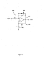
- control circuit 200 includes an amplifier 202 having a negative feedback 204 and a positive feedback 206.
- amplifier 202 may comprise a conventional operational amplifier (“op amp”) such as, but not limited to, the 741-type op amp.
- negative feedback 204 comprises a resistor (R1) 208 in electrical communication with a resistor (R2) 210.
- Positive feedback 206 comprises a standard RC (resistor 214, capacitor 212) lag which is practical and programmable. Typically amplifiers require DC power to operate. Therefore, the input voltage to control circuit 200 is constant and does not vary with time. However, the input voltage may be varied in magnitude to modify the output.
- Positive feedback 302 behaves as a lag and can be designed to modulate the rate of change 304 of the circuit.
- the gain 306 of the circuit may be varied by changing the value of the components in negative feedback 308.
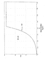
- FIG. 2 a sample output waveform of the circuit shown in Figure 2 is illustrated.
- resistor (R1) 208 is set substantially equal to the value of resistor (R2) 210 and capacitor 212 is completely discharged.
- applying a small voltage to the input of the circuit results in a voltage output equal in magnitude to the input but opposite in polarity.
- the inverting input 220 and non-inverting input 222 of amplifier 202 must be at the same potential, no charge is yet accumulated on capacitor 212.
- capacitor 212 begins charging almost immediately via resistor (R) 214 with a charge current equal to the output voltage divided by the resistance 214. As capacitor 212 charges, the voltage at non-inverting input 222 begins to exponentially increase.
- the voltage at inverting input 220 mimics the voltage at non-inverting input 222. This action causes the voltage at the output to increase, which in tum increases the charging current to capacitor 212. This operation causes the output voltage to the power supply to gradually increase and will continue until the limitations of the control circuit are reached.
- (R2) is approximately equal in value to (R1 ).
- (R2) is approximately equal in value to (R1 ).
- waveform 400 it is apparent from waveform 400 that there is a significant period prior to full operating power when (R2) is approximately equal to (R1).
- (R2) is approximately equal to (R1), a divergent exponential function results.
- Waveform 500 diverges because the current charging capacitor 212 continually increases instead of decreases. As the voltage at non-inverting input 222 increases, the voltage at inverting input 220 also increases. Capacitor 212 begins charging almost immediately and continues to increase until the voltage limits are reached. The negative and positive feedback 204, 206 of the present invention produce the divergent output waveform with the depicted rate of change.
- Figure 6 illustrates the signal from a prior art amplifier.
- Figures 5 and 6 are normalized with respect to time and voltage for exemplary purposes.
- the prior art circuit represented by waveform 600 exhibits an abrupt jump in voltage output at time equal to 1.
- waveform 600 is already at one half of the full operating power.
- exemplary waveform 500 of the present invention has only slightly increased in voltage and does not reach half operating power until after time equal to 6. Avoiding sharp increases in output voltage, especially at start-up, reduces the damaging stress on the load and increases the operating lifetime of the load.
- waveforms 500 and 600 Another advantage of the divergent waveform of the present invention is further demonstrated by comparing waveforms 500 and 600.
- exponential output waveforms (convergent and divergent) maintain a smooth shape. Differences between the two exponential waveforms lie in the rate of increase. The change in voltage with respect to time, is the rate at which the voltage changes over time.
- FIG 6 is illustrated near the horizontal asymptote of waveform 600. At time equal to 6.5, has covered approximately 3 units of time (i.e., 3.5 to 6.5).
- Exemplary waveform 500 of the present invention has a much smaller of only 1 ⁇ 2 unit of time (i.e., 6.0 to 6.5) near the vertical asymptote.
- waveform 500 exhibits a greater rate of voltage change.
- the output waveform of the present invention avoids rapid initial increases in voltage change while steadily increasing the voltage to the power supply of the load.
- Gradually increasing power in accordance for example, with the exemplary power waveform of Figure 5, results in an efficient application of power (i.e., the power supply applies power as the circuit "warms up").
- waveform 600 has covered approximately 3 units of time. This means that a change in voltage occurring at the output of the prior art circuit will occur somewhere within these 3 units of time.
- waveform 500 covers a much smaller equal to approximately 1 ⁇ 2 unit of time. The smaller interval enables a higher level of accuracy in pinpointing the time of the voltage on waveform 500.
- Yet another advantage of the present invention is its programmability. By increasing, decreasing or modifying the values of the electrical components of control circuit 200 and/or changing the input signal to the circuit, the performance of the circuit can be programmed. For particular loads in specific environments, the exponential nature of the increase in voltage during start-up may not be desirable. Rather, such applications may require a lower rate of change or a linear power curve.
- Figure 7 shows the resulting output waveforms as resistors (R2) and (R1) are varied.
- waveform 400 is duplicated as waveform 700 to illustrate an exemplary output when (R2) is substantially equal to (R1).
- the voltage at the output of control circuit 200 relative to inverting input 220 becomes relatively constant as capacitor 212 charges. This in turn supplies capacitor 212 with a current that is substantially constant and causes capacitor 212 to charge linearly.
- the rate of change further increases as illustrated by exemplary output waveform 702.
- Output waveform 704 and, more particularly, output waveform 800 of Figure 8 illustrate the near-perfect linearity of the output of circuit 200 as the ratio of (R2) to (R1) increases.
- control circuit 900 comprises two diodes 902 in negative feedback 904 and a RC lag 906 in positive feedback 908.
- diodes 902 are connected in parallel but in opposite direction, thereby allowing bipolar operation.
- the output may travel in either a positive or negative direction.
- the diode configuration causes the voltage across resistor (R) to become constant which in turn supplies capacitor (C) with a constant current.
- Capacitor (C) is now charging linearly Instead of exponentially.
- the voltage drop across diode 902 increases logarithmically with the increase in current, and decreases linearly with an increase in temperature. The current and temperature effects cause only slight yet noticeable variations.
- the input voltage and ambient temperature are dependant variables in system 900.
- the output waveform may be programmed to control the slope of the ramp (e.g., a linear ramp which steadily increases) by changing the input signal and/or the values of (R) and (C) and more specifically according to the formula where i is the current to capacitor (C).
- (R) (or any of the resistors in the circuits) can comprise a digital resistor or digital potentiometer.
- the potentiometer can be controlled by, for example, digital hardware (e.g., chip) and/or software (e.g., computer program).
- negative feedback 1006 comprises one or more zener diodes 1002 and an equal number of logic diodes 1004, and positive feedback 1008 comprises a RC lag 1010.
- Logic diodes 1004 are placed in series with each zener diode 1002 for bipolar operation. This configuration prevents the zener diodes from behaving like logic diodes in the reverse direction.
- Replacing (R1) with a combination of zener diodes 1002 and logic diodes 1004 forces the voltage across resistor (R) to remain constant.
- the current to capacitor (C) is also constant, thus causing capacitor (C) to charge linearly.
- the zener diode configuration of Figure 10 is neither voltage nor temperature dependent.
- Zener diodes 1002 are chosen to achieve temperature invariance by, for example, having a temperature coefficient complimentary to logic diodes 1004.
- FIG 11 illustrates still another embodiment of the present invention comprising a voltage divider circuit.
- Resistor (R2) is replaced by resistors (R2A) 1102 and (R2B) 1104 in circuit 1100.
- Resistors 1102 and 1104 are electrically connected to form a voltage divider.
- This embodiment is especially suited for one time soft-start functions at power up and then repeat only when power is applied again. Further, this embodiment utilizes the existing power supplies necessary to power the other circuitry such as the amplifier.
- the physical variables of the load can directly influence the amount of current the load can accept.
- a lamp filament used in a display system of an airplane cockpit may experience drastic temperature changes depending on where the plane is flying. In warmer climates, the lamp filament can withstand higher currents in less time and is usually brought to full operating current rapidly. However in colder climates, the cold lamp filament requires a slower application of current and is more susceptible to damage if current is suddenly applied.
- another embodiment of the present invention includes a sensor device to monitor the temperature of the load.
- Control system 1204 controls the application of power from power supply 1206 to load 1202. It is advantageous to determine the optimal rate to supply full operating current (e.g., when the load is properly "warmed-up").
- Sensor 1200 is suitably coupled to load 1202 to receive periodic temperature readings from the load. Temperature information is transmitted from sensor 1200 to the voltage input of control 1204. The voltage input Is increased relative to the increase in temperature of load 1202. Thus, as the load temperature increases indicating more power can be safely supplied, the voltage input is adjusted accordingly.
- This exemplary configuration permits the lower rates of change needed to reduce load damage in, for example, severely cold climates.
- similar physical variables which can effect the amount of power supplied to a load may be monitored and are intended to be included in the scope of this invention (e.g., humidity, light, pH, pressure, available power).
- control circuit of the present invention can be used for, but not limited to, testing particular types of loads.
- the unique combination of both positive and negative feedback generates a divergent waveform.
- the divergent waveform of the present invention can be replicated in a pulse pattem.
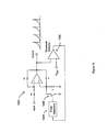
- a monopolar periodic waveform generator 1300 is disclosed in accordance with the present invention.
- the circuit configuration of Figure 2 having both positive and negative feedback is coupled to a threshold detector 1302, a pulse generator 1304 and a switch 1306.
- a threshold detector 1302 the circuit configuration of Figure 2 having both positive and negative feedback is coupled to a threshold detector 1302, a pulse generator 1304 and a switch 1306.
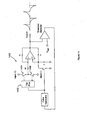
- circuit 1400 of Figure 14 comprises a flip-flop 1402, a second voltage supply (noted generally from Figure 14 as "Input (+) and Input (-)"), and at least two additional switches 1404 and 1406.
- the additional switches 1404 and 1406 each receive an input voltage signal of opposite polarity from the other.
Landscapes
- Amplifiers (AREA)
- Dc-Dc Converters (AREA)
- Control Of Voltage And Current In General (AREA)
- Control Of Amplification And Gain Control (AREA)
Abstract
Description
- The present invention relates generally to a programmable circuit and, more particularly to a circuit for generating a programmable power curve, ramp and waveform.
- Various forms of lamps, such as fluorescent and incandescent, include at least one fragile filament. Lamp filaments and other dynamic loads exhibit impedance that varies, for example, as a function of temperature (i.e., as the temperature of the filament increases due to current-induced heating, the impedance increases). When power is supplied to the lamp, the filament is usually cold and the resistance is low., At power-up, the initial current can be as high as ten to twenty times greater than the normal operating current. Repeated cold-current surges will degrade the filament and result in premature failure of the lamp.
- The high initial current can be controlled with a soft-start circuit. Soft-start circuits are used to control the rate at which power is applied to the dynamic load. Generally, it is desirable to increase the power to the load in a smooth manner. Thus, controlling the rate of power application to the lamp results in heating the filaments at a slower rate and reduces the risk of filament damage.
- One soft-start technique is a "trickle current" which provides a relatively small, continuous current to the dynamic load when it is not operating. The continuous flow of current keeps the load warm and the impedance high. When full power is suddenly applied, the surge current is reduced. The trickle current system, while simplistic, does require extraneous or sequenced power supplies and does not eliminate the surge current, only reduces it. Further, the continuous supply of current required to implement this technique can be costly and inefficient.
- Another technique for reducing the surge current effect is through a thermistor or other temperature dependent resistance. When power is initially applied, the current flows through the thermistor producing rapid heating and high resistance. As the thermistor heats up, the resistance stablilizes and the operating current is achieved. A thermistor is rugged and relatively inexpensive, but its behavior is difficult to predict. A thermistor also disssipates a significant amount of power during normal operation which can affect its resistive values.
- A series inductor may also limit surge current in some applications which require large current. Inductive chokes are magnetic components that obey Lenz's Law. At power-on, the magnetic field created by the inductor reduces the initial current and diminshes the sudden surge current to the load. In many environments, the addition of a strong magnetic field may not be desirable. Furthermore, inductive chokes tend to be bulky, heavy and dissipate power during normal operation.
- A current regulation system including a small sense resistor coupled to the load is yet another soft-start technique. The voltage across the resistor provides feedback for controlling the power supplied to the load. Such systems offer very brief control before full power-up, usually around 20 to 100 milliseconds, and this period may be too short for applications with large initial currents or particularly sensitive loads.
- The present system overcomes the prior art problems by providing a programmable circuit with low electronic component count. More particularly, the present invention provides a programmable power curve and ramp generator circuit particularly useful in a soft-start application.
- According to the present invention there is provided a programmable circuit for generating a periodic waveform comprising:
- an amplifier having a voltage input, a voltage output, a negative feedback and
- a a positive feedback, wherein said negative and positive feedbacks are electrically connected between said voltage input and said voltage output;
- a threshold detector having at least one detector input terminal connected to said amplifier, and one detector output terminal;
- a pulse generator connected to said detector output terminal; and
- a switch coupled to receive a pulse from said pulse generator; wherein the periodic waveform appears at said voltage output.
-
- These and other features, aspects, and advantages of the present invention will become better understood with regard to the following description, appended claims, and accompanying drawings where:
- Figure 1 illustrates in block format a control system in accordance with the present invention;
- Figure 2 illustrates an exemplary programmable circuit diagram in accordance with the present invention;
- Figure 3 depicts Figure 2 in block format;
- Figure 4 illustrates an output waveform of an exemplary programmable circuit in accordance with the present invention where (R2) = (R1 );
- Figure 5 illustrates in a divergent output waveform of an exemplary programmable circuit in accordance with the present invention;

- Figure 6 illustrates
in a convergent output waveform of the prior art;
- Figure 7 illustrates an output waveform of an exemplary programmable circuit in accordance with the present invention where the ratio of (R2) to (R1) is increased;
- Figure 8 illustrates an output waveform of an exemplary programmable circuit in accordance with the present inventionwhere (R2)>> (R1 );
- Figure 9 illustrates one embodiment in accordance with the present invention where (R1) comprises logic diodes;
- Figure 10 illustrates another embodiment in accordance with the present invention where (R1) comprises zener diodes;
- Figure 11 illustrates another embodiment in accordance with the present invention where (R2) comprises a voltage divider;
- Figure 12 illustrates in block format a sensor embodiment of the control system in accordance with the present invention;
- Figure 13 illustrates a periodic monopolar waveform generator in accordance with another embodiment of the present invention; and
- Figure 14 illustrates a periodic bipolar waveform generator in accordance with another embodiment of the present invention.
-
- The ensuing descriptions are preferred exemplary embodiments only, and are not intended to limit the scope, applicability, or configuration of the invention in any way. Rather, the ensuing descriptions provide a convenient description for implementing preferred embodiments of the invention, it being understood that various changes may be made in the function and arrangement of elements described in the preferred embodiments without departing from the spirit and scope of the invention as set forth in the appended claims.
- A control system according to various aspects of the present invention controls the power supplied to a load such as, for example, a lamp. In one embodiment, the control system is particularly configured to control the initial current which can damage a lamp filament. In addition, the control system of the present invention is particularly suited for lamps used in backlighting a liquid crystal display (LCD) used in various applications such as, for example, avionics displays, laptop computers, video cameras and automatic teller machine displays. Those of skill in the art will recognize that the present control system may be used in any suitable application which may be subject to damage or other adverse effects due to a high initial current. .
- Referring to Figure 1, a
control system 100 according to various aspects of the present invention controls the current application of power frompower supply 102 to load 104. In general,load 104 represents any current-sensitive load that can be damaged by a surge current at start-up. One skilled in the art will recognize thatpower supply 102 may be determined by the type of load. For example,power supply 102 may be any controllable power supply such as, but not limited to, switching power supplies (e.g., pulse width regulator) and linearly regulated power supplies. - Referring to Figure 2,
control circuit 200 includes anamplifier 202 having anegative feedback 204 and apositive feedback 206. As shown,amplifier 202 may comprise a conventional operational amplifier ("op amp") such as, but not limited to, the 741-type op amp. - In one exemplary embodiment,
negative feedback 204 comprises a resistor (R1) 208 in electrical communication with a resistor (R2) 210.Positive feedback 206 comprises a standard RC (resistor 214, capacitor 212) lag which is practical and programmable. Typically amplifiers require DC power to operate. Therefore, the input voltage to controlcircuit 200 is constant and does not vary with time. However, the input voltage may be varied in magnitude to modify the output. - The circuit may be more easily understood with reference to the exemplary block diagram of Figure 3.
Positive feedback 302 behaves as a lag and can be designed to modulate the rate ofchange 304 of the circuit. Thegain 306 of the circuit may be varied by changing the value of the components innegative feedback 308. - With reference to Figure 4, a sample output waveform of the circuit shown in Figure 2 is illustrated. In this example, assume the value of resistor (R1) 208 is set substantially equal to the value of resistor (R2) 210 and
capacitor 212 is completely discharged. In operation, applying a small voltage to the input of the circuit results in a voltage output equal in magnitude to the input but opposite in polarity. Because the invertinginput 220 andnon-inverting input 222 ofamplifier 202 must be at the same potential, no charge is yet accumulated oncapacitor 212. However,capacitor 212 begins charging almost immediately via resistor (R) 214 with a charge current equal to the output voltage divided by theresistance 214. Ascapacitor 212 charges, the voltage atnon-inverting input 222 begins to exponentially increase. The voltage at invertinginput 220 mimics the voltage atnon-inverting input 222. This action causes the voltage at the output to increase, which in tum increases the charging current tocapacitor 212. This operation causes the output voltage to the power supply to gradually increase and will continue until the limitations of the control circuit are reached. - In one embodiment of
circuit 200 of the present invention, (R2) is approximately equal in value to (R1 ). With continued reference to Figure 4, it is apparent fromwaveform 400 that there is a significant period prior to full operating power when (R2) is approximately equal to (R1). In addition, it is clear from Figure 4 that if (R2) is approximately equal to (R1), a divergent exponential function results. - Referring now to Figure 5, the voltage output waveform of the circuit of Figure 2 is illustrated.
Waveform 500 diverges because thecurrent charging capacitor 212 continually increases instead of decreases. As the voltage atnon-inverting input 222 increases, the voltage at invertinginput 220 also increases.Capacitor 212 begins charging almost immediately and continues to increase until the voltage limits are reached. The negative andpositive feedback - Figure 6 illustrates the signal from a prior art amplifier. Figures 5 and 6 are normalized with respect to time and voltage for exemplary purposes. The prior art circuit represented by
waveform 600 exhibits an abrupt jump in voltage output at time equal to 1. In fact, at time equal to 1,waveform 600 is already at one half of the full operating power. In comparison, at this same time,exemplary waveform 500 of the present invention has only slightly increased in voltage and does not reach half operating power until after time equal to 6. Avoiding sharp increases in output voltage, especially at start-up, reduces the damaging stress on the load and increases the operating lifetime of the load. - Another advantage of the divergent waveform of the present invention is further demonstrated by comparing
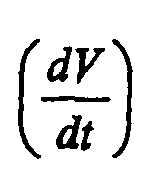
waveforms is the rate at which the voltage changes over time. With reference to Figure 6,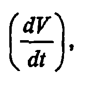 is illustrated near the horizontal asymptote of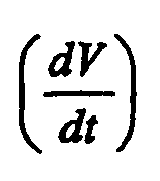
waveform 600. At time equal to 6.5,has covered approximately 3 units of time (i.e., 3.5 to 6.5).
Exemplary waveform 500 of the present invention has a much smallerof only ½ unit of time (i.e., 6.0 to 6.5) near the vertical asymptote. Therefore, in the interval of interest,
waveform 500 exhibits a greater rate of voltage change. The output waveform of the present invention avoids rapid initial increases in voltage change while steadily increasing the voltage to the power supply of the load. Gradually increasing power, in accordance for example, with the exemplary power waveform of Figure 5, results in an efficient application of power (i.e., the power supply applies power as the circuit "warms up"). - Another advantage of the present invention, also illustrated by Figures 5 and 6, is the precision timing achievable by the present invention. Referring again to
waveform 600,has covered approximately 3 units of time. This means that a change in voltage occurring at the output of the prior art circuit will occur somewhere within these 3 units of time. On the other hand,
waveform 500 covers a much smallerequal to approximately ½ unit of time. The smaller interval enables a higher level of accuracy in pinpointing the time of the voltage on
waveform 500. - Yet another advantage of the present invention, is its programmability. By increasing, decreasing or modifying the values of the electrical components of
control circuit 200 and/or changing the input signal to the circuit, the performance of the circuit can be programmed. For particular loads in specific environments, the exponential nature of the increase in voltage during start-up may not be desirable. Rather, such applications may require a lower rate of change or a linear power curve. - To illustrate the flexibility of the present invention, Figure 7 shows the resulting output waveforms as resistors (R2) and (R1) are varied. As a reference,
waveform 400 is duplicated aswaveform 700 to illustrate an exemplary output when (R2) is substantially equal to (R1). As the ratio of (R2) to (R1) increases, the voltage at the output ofcontrol circuit 200 relative to invertinginput 220 becomes relatively constant ascapacitor 212 charges. This in turn supplies capacitor 212 with a current that is substantially constant and causescapacitor 212 to charge linearly. As the ratio of (R2) to (R1) further increases, the rate of change further increases as illustrated byexemplary output waveform 702.Output waveform 704 and, more particularly,output waveform 800 of Figure 8 illustrate the near-perfect linearity of the output ofcircuit 200 as the ratio of (R2) to (R1) increases. - In another embodiment of present invention, (R1) is replaced with one or more logic diodes. Referring now to Figure 9,
control circuit 900 comprises twodiodes 902 innegative feedback 904 and a RC lag 906 inpositive feedback 908. In this embodiment,diodes 902 are connected in parallel but in opposite direction, thereby allowing bipolar operation. Thus, the output may travel in either a positive or negative direction. The diode configuration causes the voltage across resistor (R) to become constant which in turn supplies capacitor (C) with a constant current. Capacitor (C) is now charging linearly Instead of exponentially. The voltage drop acrossdiode 902 increases logarithmically with the increase in current, and decreases linearly with an increase in temperature. The current and temperature effects cause only slight yet noticeable variations. Thus, the input voltage and ambient temperature are dependant variables insystem 900. - The output waveform (not shown) may be programmed to control the slope of the ramp (e.g., a linear ramp which steadily increases) by changing the input signal and/or the values of (R) and (C) and more specifically according to the formulawhere i is the current to capacitor (C). One skilled in the art will readily recognize the capacitor formula and appreciate the inherent programmability of the present invention. For example, (R) (or any of the resistors in the circuits) can comprise a digital resistor or digital potentiometer. The potentiometer can be controlled by, for example, digital hardware (e.g., chip) and/or software (e.g., computer program).

- In Figure 10, another embodiment of the present invention,
negative feedback 1006 comprises one ormore zener diodes 1002 and an equal number oflogic diodes 1004, andpositive feedback 1008 comprises aRC lag 1010.Logic diodes 1004 are placed in series with eachzener diode 1002 for bipolar operation. This configuration prevents the zener diodes from behaving like logic diodes in the reverse direction. Replacing (R1) with a combination ofzener diodes 1002 andlogic diodes 1004 forces the voltage across resistor (R) to remain constant. The current to capacitor (C) is also constant, thus causing capacitor (C) to charge linearly. Unlikeexemplary system 900, the zener diode configuration of Figure 10 is neither voltage nor temperature dependent. Because the voltage ofzener diodes 1002 is large in comparison to the change in voltage ofdiodes 1004, the change goes unnoticed bycircuit 1000.Zener diodes 1002 are chosen to achieve temperature invariance by, for example, having a temperature coefficient complimentary tologic diodes 1004. - Figure 11 illustrates still another embodiment of the present invention comprising a voltage divider circuit. Resistor (R2) is replaced by resistors (R2A) 1102 and (R2B) 1104 in
circuit 1100. Resistors 1102 and 1104 are electrically connected to form a voltage divider. This embodiment is especially suited for one time soft-start functions at power up and then repeat only when power is applied again. Further, this embodiment utilizes the existing power supplies necessary to power the other circuitry such as the amplifier. - The physical variables of the load can directly influence the amount of current the load can accept. For example, a lamp filament used in a display system of an airplane cockpit may experience drastic temperature changes depending on where the plane is flying. In warmer climates, the lamp filament can withstand higher currents in less time and is usually brought to full operating current rapidly. However in colder climates, the cold lamp filament requires a slower application of current and is more susceptible to damage if current is suddenly applied.
- With reference to Figure 12, another embodiment of the present invention includes a sensor device to monitor the temperature of the load.
Control system 1204 controls the application of power frompower supply 1206 to load 1202. It is advantageous to determine the optimal rate to supply full operating current (e.g., when the load is properly "warmed-up").Sensor 1200 is suitably coupled to load 1202 to receive periodic temperature readings from the load. Temperature information is transmitted fromsensor 1200 to the voltage input ofcontrol 1204. The voltage input Is increased relative to the increase in temperature ofload 1202. Thus, as the load temperature increases indicating more power can be safely supplied, the voltage input is adjusted accordingly. This exemplary configuration permits the lower rates of change needed to reduce load damage in, for example, severely cold climates. Those skilled in the art will recognize that similar physical variables which can effect the amount of power supplied to a load may be monitored and are intended to be included in the scope of this invention (e.g., humidity, light, pH, pressure, available power). - Further embodiments of the control circuit of the present invention can be used for, but not limited to, testing particular types of loads. As mentioned earlier, the unique combination of both positive and negative feedback generates a divergent waveform. The divergent waveform of the present invention can be replicated in a pulse pattem. Referring now to Figure 13, a monopolar
periodic waveform generator 1300 is disclosed in accordance with the present invention. In this embodiment, the circuit configuration of Figure 2 having both positive and negative feedback is coupled to athreshold detector 1302, apulse generator 1304 and aswitch 1306. One skilled in the art will quickly recognize the functions of the circuit. - For some applications, it is desirable to generate both positive and negative pulses. The embodiment of Figure 13 can be enhanced to produce a bipolar periodic waveform. In addition to the exemplary components of Figure 13,
circuit 1400 of Figure 14 comprises a flip-flop 1402, a second voltage supply (noted generally from Figure 14 as "Input (+) and Input (-)"), and at least twoadditional switches additional switches
Claims (2)
- A programmable circuit for generating a periodic waveform comprising:an amplifier (202) having a voltage input, a voltage output, a negative feedback (204) anda positive feedback (206), wherein said negative and positive feedbacks are electrically connected between said voltage input and said voltage output;a threshold detector (1302) having at least one detector input terminal connected to said amplifier, and one detector output terminal;a pulse generator (1304) connected to said detector output terminal; anda switch (1306) coupled to receive a pulse from said pulse generator; wherein the periodic waveform appears at said voltage output.
- The programmable circuit of claim 1, further comprising a flip-flop (1402) having first and second output leads and one input lead, said input lead coupled between said pulse generator and said switch, and said first and second output leads being coupled to a first and a second power input, respectively, said second power input having an opposite polarity of said first power input.
Applications Claiming Priority (3)
| Application Number | Priority Date | Filing Date | Title |
|---|---|---|---|
| US09/575,960 US6329802B1 (en) | 2000-05-23 | 2000-05-23 | Method and apparatus for programmable power curve and wave generator |
| US575960 | 2000-05-23 | ||
| EP01939216A EP1290919A2 (en) | 2000-05-23 | 2001-05-22 | Method and apparatus for programmable power curve and wave generator |
Related Parent Applications (1)
| Application Number | Title | Priority Date | Filing Date |
|---|---|---|---|
| EP01939216A Division EP1290919A2 (en) | 2000-05-23 | 2001-05-22 | Method and apparatus for programmable power curve and wave generator |
Publications (1)
| Publication Number | Publication Date |
|---|---|
| EP1372361A1 true EP1372361A1 (en) | 2003-12-17 |
Family
ID=24302397
Family Applications (2)
| Application Number | Title | Priority Date | Filing Date |
|---|---|---|---|
| EP01939216A Withdrawn EP1290919A2 (en) | 2000-05-23 | 2001-05-22 | Method and apparatus for programmable power curve and wave generator |
| EP03015643A Withdrawn EP1372361A1 (en) | 2000-05-23 | 2001-05-22 | Method and apparatus for generating a periodic waveform |
Family Applications Before (1)
| Application Number | Title | Priority Date | Filing Date |
|---|---|---|---|
| EP01939216A Withdrawn EP1290919A2 (en) | 2000-05-23 | 2001-05-22 | Method and apparatus for programmable power curve and wave generator |
Country Status (4)
| Country | Link |
|---|---|
| US (1) | US6329802B1 (en) |
| EP (2) | EP1290919A2 (en) |
| JP (1) | JP2004501487A (en) |
| WO (1) | WO2001091522A2 (en) |
Families Citing this family (10)
| Publication number | Priority date | Publication date | Assignee | Title |
|---|---|---|---|---|
| KR100413685B1 (en) * | 2001-07-09 | 2003-12-31 | 삼성전자주식회사 | Apparatus and method for generating control voltage having phase difference |
| US7142140B2 (en) | 2004-07-27 | 2006-11-28 | Silicon Laboratories Inc. | Auto scanning ADC for DPWM |
| US7417877B2 (en) * | 2004-07-27 | 2008-08-26 | Silicon Laboratories Inc. | Digital power supply with programmable soft start |
| DE102004062728B3 (en) * | 2004-12-27 | 2006-04-06 | Insta Elektro Gmbh | Electric/electronic circuit structure for dimming multiple LEDs connected in series has a controllable source of current and a clock generator for pulse-width modulation of LED supply voltage |
| US7342577B2 (en) * | 2005-01-25 | 2008-03-11 | Honeywell International, Inc. | Light emitting diode driving apparatus with high power and wide dimming range |
| KR100786491B1 (en) * | 2007-01-02 | 2007-12-18 | 삼성에스디아이 주식회사 | Driving device of plasma display panel and plasma display device having same |
| ATE504032T1 (en) * | 2007-03-19 | 2011-04-15 | Vinko Kunc | METHOD FOR REGULATING A SUPPLY VOLTAGE |
| DE102011087440A1 (en) * | 2011-11-30 | 2013-01-31 | Osram Ag | Circuit for controlling a lighting component |
| US9261419B2 (en) | 2014-01-23 | 2016-02-16 | Honeywell International Inc. | Modular load structure assembly having internal strain gaged sensing |
| WO2022261854A1 (en) * | 2021-06-16 | 2022-12-22 | 深圳市汇顶科技股份有限公司 | Power amplifier, chip and terminal device |
Citations (4)
| Publication number | Priority date | Publication date | Assignee | Title |
|---|---|---|---|---|
| US3953783A (en) * | 1971-04-06 | 1976-04-27 | Environment/One Corporation | Low cast chopper inverter power supply and gating circuit therefor |
| US4710692A (en) * | 1986-10-16 | 1987-12-01 | Square D Company | Self calibration of the thyristor firing angel of a motor controller using a current window to determine a final value of a reference current lag phase angle |
| US4749917A (en) * | 1986-05-05 | 1988-06-07 | Angott Paul G | Two-tone dimmer circuit |
| US5146108A (en) * | 1990-09-05 | 1992-09-08 | Sony Corporation | Parabolic wave generator |
Family Cites Families (29)
| Publication number | Priority date | Publication date | Assignee | Title |
|---|---|---|---|---|
| US3821484A (en) * | 1971-03-15 | 1974-06-28 | North Electric Co | Time sharing of a supervisory receiver unit |
| US4008416A (en) * | 1973-05-29 | 1977-02-15 | Nakasone Henry H | Circuit for producing a gradual change in conduction angle |
| US3851276A (en) * | 1974-04-15 | 1974-11-26 | Rca Corp | Oscillator using controllable gain differential amplifier with three feedback circuits |
| US4209738A (en) | 1977-06-22 | 1980-06-24 | Esquire, Inc. | Regulation circuit |
| US5159260A (en) * | 1978-03-08 | 1992-10-27 | Hitachi, Ltd. | Reference voltage generator device |
| US4514701A (en) * | 1978-12-05 | 1985-04-30 | Kenji Machida | Automatic level control circuit |
| US4262234A (en) | 1979-10-12 | 1981-04-14 | Burroughs Corporation | SCR Lamp supply trigger circuit |
| US4520450A (en) | 1982-07-23 | 1985-05-28 | Westinghouse Electric Corp. | Digital ramp function generator and motor drive system including the same |
| US4503364A (en) | 1982-09-02 | 1985-03-05 | Cooper Industries, Inc. | Programming and control device for modified lead ballast for HID lamps |
| US4516036A (en) * | 1982-11-23 | 1985-05-07 | Rca Corporation | Linear ramp voltage generator circuit |
| US4603282A (en) | 1984-04-19 | 1986-07-29 | Magnavox Government And Industrial Electronics Company | Amplifier dissipation divertor circuit |
| DE3513365A1 (en) * | 1985-04-15 | 1986-10-23 | Richard Hirschmann Radiotechnisches Werk, 7300 Esslingen | Method and device for limiting switching-on currents |
| US4658204A (en) * | 1986-02-07 | 1987-04-14 | Prime Computer, Inc. | Anticipatory power failure detection apparatus and method |
| US4902938A (en) | 1986-11-15 | 1990-02-20 | Magnetek Inc. | Electronic ballast with high voltage protection |
| US5001649A (en) * | 1987-04-06 | 1991-03-19 | Alcon Laboratories, Inc. | Linear power control for ultrasonic probe with tuned reactance |
| DE58903262D1 (en) | 1988-07-06 | 1993-02-25 | Rieter Ag Maschf | SYNCHRONIZABLE DRIVE SYSTEMS. |
| US5057848A (en) * | 1989-05-30 | 1991-10-15 | Holaday Industries, Inc. | Broadband frequency meter probe |
| US5153462A (en) * | 1991-05-21 | 1992-10-06 | Advanced Micro Devices, Inc. | Programmable logic device incorporating voltage comparator |
| US5428267A (en) | 1992-07-09 | 1995-06-27 | Premier Power Systems, Inc. | Regulated DC power supply |
| US5264782A (en) | 1992-08-10 | 1993-11-23 | International Business Machines Corporation | Dropout recovery circuit |
| US5363020A (en) | 1993-02-05 | 1994-11-08 | Systems And Service International, Inc. | Electronic power controller |
| JP3197166B2 (en) | 1994-09-02 | 2001-08-13 | 株式会社小糸製作所 | Lighting circuit of discharge lamp |
| KR0149303B1 (en) | 1995-03-30 | 1998-12-15 | 김광호 | Electronic ballast for succesive feedback control system |
| KR100377064B1 (en) * | 1995-04-04 | 2003-06-02 | 학교법인 포항공과대학교 | Fully differential folded cascade cmos operational amplifier having adaptive biasing and common mode feedback circuits |
| KR0163903B1 (en) | 1995-06-05 | 1999-04-15 | 김광호 | Electronic ballast of feedback control system |
| US5670775A (en) * | 1995-06-23 | 1997-09-23 | Ardac, Inc. | Current-boosted positive feedback logarithmic transresistance amplifier for currency validators |
| KR0167900B1 (en) | 1995-12-28 | 1999-03-20 | 김광호 | Soft-Start Pulse Width Modulation Integrated Circuits |
| US5859506A (en) * | 1996-02-26 | 1999-01-12 | Lemke; Guido | High-efficiency incandescent lamp power controller |
| US5770939A (en) | 1996-05-30 | 1998-06-23 | Motorola Inc. | Programmable amplitude ramp generator for automotive voltage regulators |
-
2000
- 2000-05-23 US US09/575,960 patent/US6329802B1/en not_active Expired - Fee Related
-
2001
- 2001-05-22 WO PCT/US2001/016392 patent/WO2001091522A2/en not_active Ceased
- 2001-05-22 EP EP01939216A patent/EP1290919A2/en not_active Withdrawn
- 2001-05-22 JP JP2001586549A patent/JP2004501487A/en active Pending
- 2001-05-22 EP EP03015643A patent/EP1372361A1/en not_active Withdrawn
Patent Citations (4)
| Publication number | Priority date | Publication date | Assignee | Title |
|---|---|---|---|---|
| US3953783A (en) * | 1971-04-06 | 1976-04-27 | Environment/One Corporation | Low cast chopper inverter power supply and gating circuit therefor |
| US4749917A (en) * | 1986-05-05 | 1988-06-07 | Angott Paul G | Two-tone dimmer circuit |
| US4710692A (en) * | 1986-10-16 | 1987-12-01 | Square D Company | Self calibration of the thyristor firing angel of a motor controller using a current window to determine a final value of a reference current lag phase angle |
| US5146108A (en) * | 1990-09-05 | 1992-09-08 | Sony Corporation | Parabolic wave generator |
Also Published As
| Publication number | Publication date |
|---|---|
| US6329802B1 (en) | 2001-12-11 |
| EP1290919A2 (en) | 2003-03-12 |
| JP2004501487A (en) | 2004-01-15 |
| WO2001091522A3 (en) | 2002-05-16 |
| WO2001091522A2 (en) | 2001-11-29 |
Similar Documents
| Publication | Publication Date | Title |
|---|---|---|
| EP0720783B1 (en) | Inrush current limiter | |
| US4504776A (en) | Power saving regulated light emitting diode circuit | |
| US20030038124A1 (en) | Compact heating module with soft start | |
| US5589762A (en) | Adaptive voltage regulator | |
| US4520418A (en) | Reset circuit | |
| EP1390816A1 (en) | Rms voltage control | |
| US6329802B1 (en) | Method and apparatus for programmable power curve and wave generator | |
| US8093882B2 (en) | Low heat dissipation I/O module using direct drive buck converter | |
| US20080088290A1 (en) | System and Method for Detection of Multiple Current Limits | |
| WO2006135836A1 (en) | Regulation of electrical current through a resistive load | |
| US4538102A (en) | Power supply circuit | |
| US5360962A (en) | Heating appliance with transformerless power supply using low-loss passive divider to reduce AC line voltages | |
| US12119744B2 (en) | Circuit assembly for connecting to a current source | |
| CN220415761U (en) | Fan speed regulating circuit based on temperature | |
| US5502416A (en) | Adjustable reset threshold for an integrated regulator | |
| US5625305A (en) | Load detection apparatus | |
| US11428728B1 (en) | LED load voltage detection apparatus and method | |
| JP4141807B2 (en) | Semiconductor laser drive device | |
| CN114743494A (en) | Control circuit, driving device and display | |
| US7019500B2 (en) | Pulse width modulation power regulator and power supply system thereof | |
| US20240243568A1 (en) | Voltage control system | |
| US4340850A (en) | Temperature responsive control circuit | |
| CN217363362U (en) | Over-temperature protection module, light source driving circuit and replacement light source | |
| US20060197515A1 (en) | Pulse width modulation power regulator and power supply system thereof | |
| US20030072119A1 (en) | Solid state switch with temperature compensated current limit |
Legal Events
| Date | Code | Title | Description |
|---|---|---|---|
| PUAI | Public reference made under article 153(3) epc to a published international application that has entered the european phase |
Free format text: ORIGINAL CODE: 0009012 |
|
| 17P | Request for examination filed |
Effective date: 20030804 |
|
| AC | Divisional application: reference to earlier application |
Ref document number: 1290919 Country of ref document: EP Kind code of ref document: P |
|
| AK | Designated contracting states |
Kind code of ref document: A1 Designated state(s): AT BE CH CY DE DK ES FI FR GB GR IE IT LI LU MC NL PT SE TR |
|
| AX | Request for extension of the european patent |
Extension state: AL LT LV MK |
|
| AKX | Designation fees paid |
Designated state(s): AT BE CH CY DE DK ES FI FR GB GR IE IT LI LU MC NL PT SE TR |
|
| 17Q | First examination report despatched |
Effective date: 20040827 |
|
| STAA | Information on the status of an ep patent application or granted ep patent |
Free format text: STATUS: THE APPLICATION IS DEEMED TO BE WITHDRAWN |
|
| 18D | Application deemed to be withdrawn |
Effective date: 20050604 |