EP1372352A2 - Earpiece for wideband telephone handsets - Google Patents
Earpiece for wideband telephone handsets Download PDFInfo
- Publication number
- EP1372352A2 EP1372352A2 EP03253240A EP03253240A EP1372352A2 EP 1372352 A2 EP1372352 A2 EP 1372352A2 EP 03253240 A EP03253240 A EP 03253240A EP 03253240 A EP03253240 A EP 03253240A EP 1372352 A2 EP1372352 A2 EP 1372352A2
- Authority
- EP
- European Patent Office
- Prior art keywords
- diaphragm
- resonator
- cap
- leak
- earpiece
- Prior art date
- Legal status (The legal status is an assumption and is not a legal conclusion. Google has not performed a legal analysis and makes no representation as to the accuracy of the status listed.)
- Granted
Links
Images


Classifications
-
- H—ELECTRICITY
- H04—ELECTRIC COMMUNICATION TECHNIQUE
- H04M—TELEPHONIC COMMUNICATION
- H04M1/00—Substation equipment, e.g. for use by subscribers
- H04M1/02—Constructional features of telephone sets
- H04M1/03—Constructional features of telephone transmitters or receivers, e.g. telephone hand-sets
-
- H—ELECTRICITY
- H04—ELECTRIC COMMUNICATION TECHNIQUE
- H04R—LOUDSPEAKERS, MICROPHONES, GRAMOPHONE PICK-UPS OR LIKE ACOUSTIC ELECTROMECHANICAL TRANSDUCERS; ELECTRIC HEARING AIDS; PUBLIC ADDRESS SYSTEMS
- H04R31/00—Apparatus or processes specially adapted for the manufacture of transducers or diaphragms therefor
- H04R31/003—Apparatus or processes specially adapted for the manufacture of transducers or diaphragms therefor for diaphragms or their outer suspension
Definitions
- the present invention relates to telephony earpiece receivers for wideband telephone handsets or headsets, in low and high leak conditions and in particular to 7kHz audio in telephony.
- Receivers for a handset or headset are conventionally designed using a lumped parameter model. Using this model, the speaker diaphragm behaves as a piston, as discussed for example in Theory & Design of Loudspeaker Enclosures by J.E. Benson; (1996) Howard W. Sams & Co. ISBN 0-7906-1093-0 and High Performance Loudspeakers, by M. Colloms,(1997) John Wiley ISBM 0-471- 97089-1. In section 7.11 of Acoustics (L.L.
- Beranek (1954) Acoustical Society of America (1996); ISBN 0-88318-494-X), Beranek recognises that the typical loudspeaker has a modal behaviour but concludes that no "tractable mathematical treatment is available by which the exact performance of a loudspeaker can be predicted.". Beranek concludes that loudspeakers must be designed to minimise the diaphragm modal behaviour to permit the assumption that the cone of the diaphragm moves as a unit. Numerical methods such as Finite Element Methods (FEM) or Boundary Element Methods (BEM) allow accurate computation of the diaphragm vibration field and the associated acoustic radiated field.
- FEM Finite Element Methods
- BEM Boundary Element Methods
- Telephony receivers are designed to provide a frequency response for the traditional telephony band of 300-3000Hz coupled to an ITU-P.57 type 1 (IEC318) artificial ear. Some telephony receivers have been designed for a low impedance-type artificial ear but again, only for the traditional telephony band. In conventional telephony receiver designs, the exact position of leaks or resonators with respect to diaphragm geometry does not matter. Measures to counter the modal behaviour of the diaphragm result in the use of filters that generally make the device large and inefficient.
- US Pat 5,953,414 to Abraham & Dufossé discloses a piezoelectric speaker capsule for a telephone handset with leaks behind the diaphragm and a Helmholtz resonator to build the high frequency end of the earpiece. Due to the rigidity of this type of diaphragm, only one mode, namely the piston mode, is used and the rear cavity cannot block the diaphragm significantly to modify the vibration frequency.
- the speaker capsule is not designed to make several vibration modes appear in the frequency range of interest, even if leaks are provided to dampen the vibration field amplitudes of the disk.
- WO 99/35880 discloses a low impedance-type earpiece. Using a front resonator, the diaphragm is uniformly loaded and thus the device is less sensitive to externally applied acoustic load. This design is again based on the simplified lumped parameter model.
- US Pat 5,058,154 to Morten discloses a low acoustic impedance earpiece based on a pure acoustic ohmic connection between the diaphragm and the exterior of the handset.
- the path can be any shape but must have some sound damping material in it.
- This earpiece is designed based on the traditional model in which the diaphragm is modelled as a piston and the acoustic damping material is provided to deal with the unwanted diaphragm mode.
- US Pat 5,784,340 to Kanai discloses a piezoelectric earpiece in which acoustical design considerations are limited to the resonator volume which is damped by a mesh and one or more holes.
- a method of providing a handset or headset earpiece that provides a substantially flat frequency response over a wide frequency range. This is accomplished by exploiting the modal nature of the transducer diaphragm.
- prior art electro-acoustic simulations are used, taking into consideration the discrete nature of the system (lumped parameter) where the modal nature of the diaphragm is not taken into consideration.
- the diaphragm is considered as a piston.
- at least two diaphragm vibration modes are taken into consideration and serve as a basis for the design.
- aspects of the present invention are based on the vibration modal nature of the speaker diaphragm and the behaviour of a system diaphragm/thin fluid layer when coupled to different resonators and leaks.
- aspects of the present invention exploit axi-symmetric modes of the diaphragm. This is accomplished by determining the diaphragm vibration modes of interest and providing the acoustical circuitry (holes, leaks, cavities, etc.) to enhance, damp, or block these modes.
- the arrangement of an aspect of the present invention de-couples, to some extent, the effect of some of the leaks and the resonator providing enhanced low frequency performance without mid-range side effects.
- a device with desired acoustical response that is easily manufactured and is very small.
- the device includes a front resonator and a rear resonator with appropriately placed holes or slits to shape the response, as required. Only two parts are provided for the rear resonator and the front resonator is moulded into the handset housing.
- the earpiece is developed to meet the standard ITU-P.311.
- the present invention can be used in a cell phone or a headset.
- the cap having a combination of a leak and resonator holes, allows a thin design, the rear cap thickness being an adjustable parameter.
- a method of manufacturing a telephony earpiece includes providing a speaker diaphragm, constraining speaker diaphragm vibration modes using a cap to provide a thin cavity between the cap and the diaphragm, damping a first diaphragm and cavity resonance peak by a first slow leak in the cap, the first slow leak positioned such that a diaphragm vibration field is not significantly affected, building a low end frequency response using a rear resonator in the cap, enhancing high frequency end response using a front resonator on an opposite side of the diaphragm as the cap, the front resonator including a plurality of holes and a front cavity, the plurality of holes positioned to affect resonator frequency and response amplitude, and tuning the earpiece using a second leak to adjust amplitude of low frequency end response.
- a telephony earpiece device in another aspect of an embodiment of the present invention, there is provided a telephony earpiece device.
- the earpiece device includes a speaker diaphragm, a rear cap disposed on a rear side of the diaphragm to provide a cavity between the cap and the diaphragm for constraining the speaker diaphragm vibration modes, the cap having a slow leak for damping a first resonance peak and a rear resonator for building a low end frequency response, and a front resonator including a plurality of holes and a front cavity, the plurality of holes positioned for enhancing high frequency end response, the front resonator including a leak for adjusting low frequency end response amplitude.
- a prior art ITU-T P.57 type 3.2 "high leak” or “low leak” artificial ear was employed in the development of a preferred embodiment of the present invention.
- Other artificial ears can be employed, such as type 3.3 or 3.4.
- the artificial ear includes a cavity and a tube whose respective dimensions are close to the "average” human ear.
- the low leak version of the artificial ear type 3.2 has two thin slots while the high leak version has a number of holes. These versions simulate the handset either tightly or loosely sealed on the ear.
- EEP Ear Reference Point
- the artificial ear microphone membrane is located at the ear drum position (DRP or Drum Reference Point).
- the pressure is measured at the ERP (Ear Reference Point), however.
- a correction is introduced when performing the measurement. This correction is shown in Figure 2.
- the pressure can be measured directly at the ERP when the earpiece is sealed on the artificial ear by using a probe microphone in order to avoid using the correction ERP/DRP in the open ear condition, in accordance with recommendation ITU-P.311.
- a modified earpiece with a groove at the front face can be used in such a configuration.
- the present invention exploits some loudspeaker diaphragm vibration eigenmodes and classical Helmholtz resonators to get a response, which is as wide and as flat as possible.
- a 30-mm diaphragm is used in the following description for exemplary purposes.
- the first resonance frequency of the diaphragm is about 400 Hz.
- a modal analysis of the diaphragm exhibits the vibration mode shapes ⁇ i associated with the diaphragm resonant frequencies in-vacuo.
- An exemplary modal analysis for a circular diaphragm is shown in Figures 3a to 3c and exemplary modes are shown in Figures 4a and 4b.
- the vibration field is dominated by the first diaphragm mode (up-and-down movement ( Figure 4a)) in a wide band of frequencies.
- Other modes can contribute to the vibration, primarily modes having an axi-symmetric shape relative to an axis normal to the centre of the diaphragm surface.
- the first speaker diaphragm axi-symmetric eigenmodes in the low and medium frequency range are of interest and are described below.
- antinode is used in referring to mode-shape points having maximum amplitude and nodes or nodal lines to areas where mode-shapes have zero amplitude.
- the diaphragm couples to a thin rigid fluid cavity, the diaphragm experiences a strong modification of its vibration field. Particularly, the vibration modes of the diaphragm coupled with the cavity are very different from that in free air. This characteristic is exploited in an aspect of the present invention.
- FIG. 5 shows a preferred embodiment of the audio earpiece of the present invention, indicated generally by the numeral 20.
- the speaker diaphragm 22 is partially “blocked" with a cap 24 which is tightly closed at the rear side of the speaker diaphragm 22.
- a cap 24 which is tightly closed at the rear side of the speaker diaphragm 22.
- only a thin layer of fluid is present in the cavity 23 behind the diaphragm 22.
- the diaphragm vibration field in Figure 4a is inhibited since it induces a volume variation and thus a pressure variation in the cavity.
- the vibration field shown in Figure 4b occurs as there is no significant volume variation of the cavity and thus the pressure field is constant.
- the presence of a thin rigid cavity with a thin layer of fluid contributes to partially block a diaphragm vibration field such as that shown in Figure 4a and to favour a vibration field such as that shown in Figure 4b, maintaining the pressure field inside substantially constant.
- the first resonance occurs in the medium frequency range and the corresponding diaphragm 22 shape is dominated by the contribution of the natural mode ⁇ 10 , with a reduced ⁇ 00 contribution, as shown in Figure 6.
- the final first coupled frequency of the system diaphragm/cavity depends on the volume of the fluid layer and the initial characteristics of the diaphragm 22.
- the dimensions of the rigid cavity are optimised according to the characteristics of the diaphragm 22 used for building the earpiece 20. Note that the Figures are given here for illustration purposes and are based on the diaphragm 22 presented in Figure 4, for exemplary purposes.
- the overall vibration amplitudes are reduced by using a thin fluid layer to block the diaphragm 22.
- Low acoustic power is sufficient for the earpiece 20 and therefore there is a trade off to blocking the diaphragm 22 since electro-acoustic efficiency is reduced for the modified acoustic response.
- the first coupled mode resonant frequency is experimentally tuned to about 2.4 kHz.
- the cap 24 includes a thin slot 26 for damping the first resonance peak of the system diaphragm/cavity (at 2.4 kHz in the present example).
- the thin slot 26 introduces a "slow" leak inducing friction of the fluid under pressure as the fluid passes through the thin slot 26.
- the size of the thin slot 26 is dependent on the diameter or length of the slot 26 and the cap 24 thickness.
- the slot is large with a nylon screen or a porous material (open cell foam, felt....) to ensure that a slow leak is introduced.
- the dimensions of the thin slot 26, t, g and d, shown in Figure 7 are optimised to provide a low frequency resonator and a diaphragm/cavity coupled frequency close to 3kHz.
- the position of the slot 26 is important since it impacts the response of the diaphragm 22. If the slot is located close to the centre of the diaphragm 22, the mode n 1 ( ⁇ 00 ) contribution reappears in the displacement field because the pressure field is not constant in the cavity.
- the slot 26 in the cap 24 (1/1000 to 5/1000 inch) is located far from mode ⁇ 00 antinode and preferably as far as possible from the centre of the diaphragm 22, i.e. all around the speaker.
- the slot 26 dimensions are adjusted to strongly dampen the resonance peak and account for a shift in the frequency of the resonance peak up depending on the slot characteristics. In the present example, the resonance peak is shifted from about 2.4 to about 2.8-2.9 kHz.
- An all circular slot is preferable to small holes due to the axi-symmetric nature and a uniform spread viscous damping all around.
- the pressure in the thin fluid layer is no longer constant because of the slot.
- the pressure field amplitudes tend to "follow" the diaphragm 22 displacement field amplitudes, as confirmed through finite element FE/BE analysis.
- As the slot is close to a node of ⁇ 00 (area of low amplitude), it does not significantly impact the shape of the vibration field. It simply has a damping effect and a frequency shift effect.
- the slot is optimised according to the dimensions of the cap cavity, cap depth and the diaphragm 22.
- Resonator holes or tubes 28 are introduced into the cap 24 to reach the low frequency end response. They are placed as close as possible to a diaphragm nodal line (subject to industrial design considerations) and avoid the centre area where high-pressure field occur. These tubes 28 (Helmholtz's resonator tubes) are used to exploit the rear cap cavity (the thin layer of fluid behind the diaphragm 22). The resonator is tuned in the present embodiment, to about 120-150 Hz, by adjusting the number of tubes 28, the tube length and opening area. Since the system is fully coupled, opening holes in the cap influences the diaphragm/cavity system frequency response. Due to the new leak introduced by the Helmholtz resonator design, the coupled mode resonance shifts slightly up from 2.8 kHz to 2.9 kHz, in a frequency range where it replicates the ERP/DRP correction curve shown in Figure 2.
- a front resonator 30 with holes (tubes) 32 and a cavity 33 is located in front of the speaker diaphragm 22, as shown in Figures 5 and 8.
- the front resonator 30 is intended to enhance the response at high frequency close to 6 kHz. Parameters of this resonator are adjusted taking into account the coupling with the diaphragm 22, the rear cap 24 and the artificial ear characteristics. These parameters are adjusted using FEM/BEM methods or by experimentation.
- the front resonator 30 is optimised by adjusting the number of resonator tubes 32, the diameter and the depth of these tubes 32.
- the position of the tubes 32 in the front resonator 30 significantly impacts the frequency resonance and peak amplitude of the resonator 30 when a thin cavity is employed. This is a result of the non-constant nature of the pressure field in the front cavity.
- the pressure field in the front cavity with the tubes 32 in the front resonator 30, tends to follow the diaphragm vibration field and has a maximum close to the diaphragm centre. If holes are opened in this area, the diaphragm is not able to compress properly the fluid in the front cavity. If holes are opened on an external ring, then the cavity volume can be properly compressed and the Helmholtz resonator works properly.
- the front resonator 30 can be moulded in the telephone handset.
- Figure 9 illustrates the sensitivity of different systems, measured when sealed on an artificial ear type 3.2 "low leak" (Brüel & Kj ⁇ r 4195).
- the measurement displays the sensitivity at the DRP (Drum Reference Point).
- the curve "earpiece” is corrected using the DRP-ERP curve in Figure 2.
- Figure 10 shows the resultant curve with the ERP-DRP correction.
- the earpiece sensitivity at ERP is substantially flat and falls within the 8 dB limit of the receive standard in Figure 1.
- the maximum variation for this design is approximately 6.5 dB and thus, there is some tolerance for manufacturing variations.
- the earpiece 20 is tuned by adding a leak 35 at the diaphragm 22 / front resonator 30 interface and/or at the front resonator 30 / ear interface.
- the leak is added to adjust the amplitude of the low frequency end response for making it "leak tolerant".
- the leak induces a drop in the low frequency end sensitivity when the handset is not in tight contact with the ear.
- This leak also inhibits the effects of variations in the diaphragm 22 characteristics from one diaphragm 22 to another.
- the leak is located either at the front resonator 30 cavity or outside the handset. Referring to Figure 8, the leak is produced by adding stands 34 on the outer surface of the front resonator 30.
- the leak is produced by a set of cut outs or, more preferably, is a continuous slow leak around the handset with local stands 34 to ensure a tight diaphragm 22 frame/front resonator 30 contact.
- the slow leak primarily affects the sensitivity low-frequency end below 1.0 to 1.5 kHz.
- the leak generally has little effect on the wide peak at 2.9 kHz and the high resonance peak close to 6 kHz. Thus, this leak is useful for tuning the low frequency sensitivity.
- the high leak earpiece 20 rear cap 24 and front resonator 30 are designed in the same manner as described above.
- the earpiece 20 parameters are tuned using, for example, the Type 3.2 artificial ear "high leak” version or, alternatively the Type 3.3 artificial ear (on the head and torso simulator).
- optimisation of the rear cap 24 generally results in a wider slot 26 and increased diameter of holes 28 in the cap 24 (and possibly increased number of holes 28). Additionally, as the frequency response amplitude is increased in the low frequency end to compensate for the leak at the front resonator 30 / listener ear interface, no leak is open at the diaphragm 22 / front resonator 30 interface.
- Figure 11 shows the 7kHz high leak earpiece frequency response at ERP on an artificial ear type 3.2 "high-leak". The response shown in Figure 11 fits in the mask for wideband audio handset (recommendation ITU-P.311). The darker curve describes the earpiece frequency response when covered with low-density foam.
- the frequency response at ERP of the earpiece 20 applied to Type 3.2 artificial ear version "High-leak” is similar to the frequency response of the handset earpiece 20 applied to Type 3.2 artificial ear version "Low-leak". It is to be understood that the present embodiment can be extended to a handset working in high leak conditions, such as a cell phone handset to meet recommendation ITU-P. 311 shown in Figure 1.
Landscapes
- Engineering & Computer Science (AREA)
- Signal Processing (AREA)
- Manufacturing & Machinery (AREA)
- Physics & Mathematics (AREA)
- Acoustics & Sound (AREA)
- Telephone Set Structure (AREA)
- Obtaining Desirable Characteristics In Audible-Bandwidth Transducers (AREA)
Abstract
Description
- The present invention relates to telephony earpiece receivers for wideband telephone handsets or headsets, in low and high leak conditions and in particular to 7kHz audio in telephony.
- Receivers for a handset or headset are conventionally designed using a lumped parameter model. Using this model, the speaker diaphragm behaves as a piston, as discussed for example in Theory & Design of Loudspeaker Enclosures by J.E. Benson; (1996) Howard W. Sams & Co. ISBN 0-7906-1093-0 and High Performance Loudspeakers, by M. Colloms,(1997) John Wiley ISBM 0-471- 97089-1. In section 7.11 of Acoustics (L.L. Beranek; (1954) Acoustical Society of America (1996); ISBN 0-88318-494-X), Beranek recognises that the typical loudspeaker has a modal behaviour but concludes that no "tractable mathematical treatment is available by which the exact performance of a loudspeaker can be predicted...". Beranek concludes that loudspeakers must be designed to minimise the diaphragm modal behaviour to permit the assumption that the cone of the diaphragm moves as a unit. Numerical methods such as Finite Element Methods (FEM) or Boundary Element Methods (BEM) allow accurate computation of the diaphragm vibration field and the associated acoustic radiated field.
- Telephony receivers are designed to provide a frequency response for the traditional telephony band of 300-3000Hz coupled to an ITU-P.57 type 1 (IEC318) artificial ear. Some telephony receivers have been designed for a low impedance-type artificial ear but again, only for the traditional telephony band. In conventional telephony receiver designs, the exact position of leaks or resonators with respect to diaphragm geometry does not matter. Measures to counter the modal behaviour of the diaphragm result in the use of filters that generally make the device large and inefficient.
- The prior art provides insight into the approaches taken to counter modal behaviour, but none of the prior art explicitly exploits the modal nature of the diaphragm.
- For example, US Pat 5,953,414 to Abraham & Dufossé discloses a piezoelectric speaker capsule for a telephone handset with leaks behind the diaphragm and a Helmholtz resonator to build the high frequency end of the earpiece. Due to the rigidity of this type of diaphragm, only one mode, namely the piston mode, is used and the rear cavity cannot block the diaphragm significantly to modify the vibration frequency. The speaker capsule is not designed to make several vibration modes appear in the frequency range of interest, even if leaks are provided to dampen the vibration field amplitudes of the disk.
- US Pat 5,729,605 to Bobisuthi et al. discloses several configurations for adjusting the frequency response by varying various design parameters such as rear cavity size and leaks or front resonator leaks. Bobisuthi et al. disclose designs based on the lumped parameter model. Thus, the particular location of holes with respect to the diaphragm does not matter. Further, hole locations that excite unwanted modes are compensated for by adding or modifying a resonator.
- WO 99/35880 (Williams & Mercer) discloses a low impedance-type earpiece. Using a front resonator, the diaphragm is uniformly loaded and thus the device is less sensitive to externally applied acoustic load. This design is again based on the simplified lumped parameter model.
- US Pat 5,058,154 to Morten discloses a low acoustic impedance earpiece based on a pure acoustic ohmic connection between the diaphragm and the exterior of the handset. The path can be any shape but must have some sound damping material in it. This earpiece is designed based on the traditional model in which the diaphragm is modelled as a piston and the acoustic damping material is provided to deal with the unwanted diaphragm mode.
- US Pat 5,784,340 to Kanai discloses a piezoelectric earpiece in which acoustical design considerations are limited to the resonator volume which is damped by a mesh and one or more holes.
- In one aspect of the present invention, there is provided a method of providing a handset or headset earpiece that provides a substantially flat frequency response over a wide frequency range. This is accomplished by exploiting the modal nature of the transducer diaphragm. Generally, prior art electro-acoustic simulations are used, taking into consideration the discrete nature of the system (lumped parameter) where the modal nature of the diaphragm is not taken into consideration. In these prior art systems the diaphragm is considered as a piston. In an aspect of the present invention, however, at least two diaphragm vibration modes are taken into consideration and serve as a basis for the design.
- Aspects of the present invention are based on the vibration modal nature of the speaker diaphragm and the behaviour of a system diaphragm/thin fluid layer when coupled to different resonators and leaks. Aspects of the present invention exploit axi-symmetric modes of the diaphragm. This is accomplished by determining the diaphragm vibration modes of interest and providing the acoustical circuitry (holes, leaks, cavities, etc.) to enhance, damp, or block these modes. The arrangement of an aspect of the present invention de-couples, to some extent, the effect of some of the leaks and the resonator providing enhanced low frequency performance without mid-range side effects.
- In a particular aspect of a preferred embodiment, there is provided a device with desired acoustical response that is easily manufactured and is very small. The device includes a front resonator and a rear resonator with appropriately placed holes or slits to shape the response, as required. Only two parts are provided for the rear resonator and the front resonator is moulded into the handset housing. The earpiece is developed to meet the standard ITU-P.311.
- Advantageously, the present invention can be used in a cell phone or a headset. In an aspect of the present invention, the cap having a combination of a leak and resonator holes, allows a thin design, the rear cap thickness being an adjustable parameter.
- In a particular aspect of an embodiment of the present invention, there is provided a method of manufacturing a telephony earpiece. The method includes providing a speaker diaphragm, constraining speaker diaphragm vibration modes using a cap to provide a thin cavity between the cap and the diaphragm, damping a first diaphragm and cavity resonance peak by a first slow leak in the cap, the first slow leak positioned such that a diaphragm vibration field is not significantly affected, building a low end frequency response using a rear resonator in the cap, enhancing high frequency end response using a front resonator on an opposite side of the diaphragm as the cap, the front resonator including a plurality of holes and a front cavity, the plurality of holes positioned to affect resonator frequency and response amplitude, and tuning the earpiece using a second leak to adjust amplitude of low frequency end response.
- In another aspect of an embodiment of the present invention, there is provided a telephony earpiece device. The earpiece device includes a speaker diaphragm,a rear cap disposed on a rear side of the diaphragm to provide a cavity between the cap and the diaphragm for constraining the speaker diaphragm vibration modes, the cap having a slow leak for damping a first resonance peak and a rear resonator for building a low end frequency response, and a front resonator including a plurality of holes and a front cavity, the plurality of holes positioned for enhancing high frequency end response, the front resonator including a leak for adjusting low frequency end response amplitude.
- The invention will be better understood with reference to the drawings, and following description, in which:
- Figure 1 is a graph showing a 7 kHz handset receive mask according to recommendation ITU-P.311;
- Figure 2 is a graph showing a drum reference point/ear reference point correction curve for measurement using an artificial ear microphone and a probe microphone of the prior art, normalised at 1kHz;
- Figures 3a, b and c show finite element modelling of a small speaker diaphragm showing first two axi-symmetric modes;
- Figures 4a and 4b are cross sectional side views of a small speaker backed with a thin layer of fluid, illustrating exemplary vibration modes;
- Figure 5a is an exploded perspective view of an earpiece according to a an embodiment of the present invention;
- Figure 5b is a cross-sectional side view of the earpiece of Figure 5a.
- Figures 6a to 6c include a graph showing the first resonance of the coupled system diaphragm/thin fluid layer and a corresponding diaphragm shape dominated by a contribution of natural mode χ10 with a reduced χ00 contribution;
- Figure 7 is a perspective view of a cap of the earpiece of Figure 5a;
- Figure 8 is a perspective view of a front resonator of the earpiece of Figure 5a, including a close-up view of one of four stands of the front resonator;
- Figure 9 is a frequency -sensitivity graph of the earpiece of Figure 5a;
- Figure 10 is a frequency-response graph of the earpiece of Figure 5a; and
- Figure 11 is a frequency - response graph of a 7kHz "high leak" earpiece according to an embodiment of the present invention.
-
- A prior art ITU-T P.57 type 3.2 "high leak" or "low leak" artificial ear was employed in the development of a preferred embodiment of the present invention. Other artificial ears can be employed, such as type 3.3 or 3.4. The artificial ear includes a cavity and a tube whose respective dimensions are close to the "average" human ear. The low leak version of the artificial ear type 3.2 has two thin slots while the high leak version has a number of holes. These versions simulate the handset either tightly or loosely sealed on the ear. In an object of an aspect of the present invention, it is desirable to have an earpiece receive frequency curve at Ear Reference Point (ERP) that is flatter than that of the prior art and fits in the mask in Figure 1 (from recommendation ITU P.311).
- The artificial ear microphone membrane is located at the ear drum position (DRP or Drum Reference Point). The pressure is measured at the ERP (Ear Reference Point), however. Thus, a correction is introduced when performing the measurement. This correction is shown in Figure 2.
- The pressure can be measured directly at the ERP when the earpiece is sealed on the artificial ear by using a probe microphone in order to avoid using the correction ERP/DRP in the open ear condition, in accordance with recommendation ITU-P.311. A modified earpiece with a groove at the front face can be used in such a configuration.
- The present invention exploits some loudspeaker diaphragm vibration eigenmodes and classical Helmholtz resonators to get a response, which is as wide and as flat as possible.
- A 30-mm diaphragm is used in the following description for exemplary purposes. The first resonance frequency of the diaphragm is about 400 Hz.
- Referring to eigenmodes or modes, as will be understood by those of skill in the art, a modal analysis of the diaphragm exhibits the vibration mode shapes Φ i associated with the diaphragm resonant frequencies in-vacuo. An exemplary modal analysis for a circular diaphragm is shown in Figures 3a to 3c and exemplary modes are shown in Figures 4a and 4b.
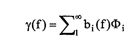
- When voltage is applied on loudspeaker pins, an electromagnetic force is generated on the voice coil. The resulting diaphragm displacement (or acceleration) vibration field vs. frequency γ(f) is the linear sum of the diaphragm vibration modes Φ i :where bi(ƒ) i=1,2...... is a unique set of coefficients depending on frequency.
- Due to the direction of the electromagnetic force on the voice coil, the vibration field is dominated by the first diaphragm mode (up-and-down movement (Figure 4a)) in a wide band of frequencies. Other modes can contribute to the vibration, primarily modes having an axi-symmetric shape relative to an axis normal to the centre of the diaphragm surface.
- The first speaker diaphragm axi-symmetric eigenmodes in the low and medium frequency range are of interest and are described below.
- The natural mode shapes shown in Figures 3b and 3c are present in any speaker. The frequency and rank of these mode shapes can vary. By analogy with a perfect thin elastic "disk" membrane, (with comparable boundary conditions) these natural modes are denoted as χr. Where, r is the number of circular nodal lines (except the boundary) and is the number of diametrical nodal lines. Mode χ00 and mode χ10 generally occur in any circular speaker diaphragm and are of particular interest. The frequency of these two modes is important.
- It should be noted that the term antinode is used in referring to mode-shape points having maximum amplitude and nodes or nodal lines to areas where mode-shapes have zero amplitude. Many other modes exist for the speaker diaphragm between 400 Hz and 5500 Hz. Modes having an axi-symmetric shape are of primary interest.
- Coupled to a thin rigid fluid cavity, the diaphragm experiences a strong modification of its vibration field. Particularly, the vibration modes of the diaphragm coupled with the cavity are very different from that in free air. This characteristic is exploited in an aspect of the present invention.
- Reference is now made to Figure 5 to show a preferred embodiment of the audio earpiece of the present invention, indicated generally by the numeral 20. In order to exploit the modal nature of the
diaphragm 22, in particular the χ10 mode, thespeaker diaphragm 22 is partially "blocked" with acap 24 which is tightly closed at the rear side of thespeaker diaphragm 22. Thus, only a thin layer of fluid is present in thecavity 23 behind thediaphragm 22. This results in a single diaphragm resonance in the frequency range 100Hz-6 kHz, referred to herein as the first diaphragm coupled mode of the system diaphragm/thin fluid layer. Coupled with a thin rigid cavity as described, the diaphragm acceleration field (or vibration field) is dominated by the χ10 mode contribution. Due to the size of the diaphragm (diameter = 30mm), the pressure field is constant in the perfectly enclosed thin fluid layer. No standing waves exist and thus no pressure variations occur in the cavity below about 5 kHz. The only diaphragm displacement fields that exist are those that respect the constant pressure in the cavity, i.e. fields that do not induce a significant volume variation in the fluid layer. Thus, the first mode (mode χ00 shown in Figure 4a) contribution in the displacement field is partially blocked since it induces a strong volume variation in the fluid layer. - The diaphragm vibration field in Figure 4a is inhibited since it induces a volume variation and thus a pressure variation in the cavity. The vibration field shown in Figure 4b occurs as there is no significant volume variation of the cavity and thus the pressure field is constant. The presence of a thin rigid cavity with a thin layer of fluid contributes to partially block a diaphragm vibration field such as that shown in Figure 4a and to favour a vibration field such as that shown in Figure 4b, maintaining the pressure field inside substantially constant.
- Therefore, in the
diaphragm 22 and thin rigid cavity, the first resonance occurs in the medium frequency range and the correspondingdiaphragm 22 shape is dominated by the contribution of the natural mode χ10, with a reduced χ00 contribution, as shown in Figure 6. - The final first coupled frequency of the system diaphragm/cavity depends on the volume of the fluid layer and the initial characteristics of the
diaphragm 22. - To achieve a diaphragm frequency response close to the one shown in figure 6a, the dimensions of the rigid cavity are optimised according to the characteristics of the
diaphragm 22 used for building theearpiece 20. Note that the Figures are given here for illustration purposes and are based on thediaphragm 22 presented in Figure 4, for exemplary purposes. - The overall vibration amplitudes are reduced by using a thin fluid layer to block the
diaphragm 22. Low acoustic power is sufficient for theearpiece 20 and therefore there is a trade off to blocking thediaphragm 22 since electro-acoustic efficiency is reduced for the modified acoustic response. In the present example, the first coupled mode resonant frequency is experimentally tuned to about 2.4 kHz. - Referring now to Figure 7, the
cap 24 is shown. Thecap 24 includes athin slot 26 for damping the first resonance peak of the system diaphragm/cavity (at 2.4 kHz in the present example). Thethin slot 26 introduces a "slow" leak inducing friction of the fluid under pressure as the fluid passes through thethin slot 26. The size of thethin slot 26 is dependent on the diameter or length of theslot 26 and thecap 24 thickness. In an alternative embodiment, the slot is large with a nylon screen or a porous material (open cell foam, felt....) to ensure that a slow leak is introduced. The dimensions of thethin slot 26, t, g and d, shown in Figure 7 are optimised to provide a low frequency resonator and a diaphragm/cavity coupled frequency close to 3kHz. - The position of the
slot 26 is important since it impacts the response of thediaphragm 22. If the slot is located close to the centre of thediaphragm 22, the mode n 1 (χ00) contribution reappears in the displacement field because the pressure field is not constant in the cavity. In order to dampen the coupled mode, theslot 26 in the cap 24 (1/1000 to 5/1000 inch) is located far from mode χ00 antinode and preferably as far as possible from the centre of thediaphragm 22, i.e. all around the speaker. Theslot 26 dimensions are adjusted to strongly dampen the resonance peak and account for a shift in the frequency of the resonance peak up depending on the slot characteristics. In the present example, the resonance peak is shifted from about 2.4 to about 2.8-2.9 kHz. An all circular slot is preferable to small holes due to the axi-symmetric nature and a uniform spread viscous damping all around. The pressure in the thin fluid layer is no longer constant because of the slot. The pressure field amplitudes tend to "follow" thediaphragm 22 displacement field amplitudes, as confirmed through finite element FE/BE analysis. As the slot is close to a node of χ00 (area of low amplitude), it does not significantly impact the shape of the vibration field. It simply has a damping effect and a frequency shift effect. - In order to achieve the desired result, the slot is optimised according to the dimensions of the cap cavity, cap depth and the
diaphragm 22. - Resonator holes or
tubes 28 are introduced into thecap 24 to reach the low frequency end response. They are placed as close as possible to a diaphragm nodal line (subject to industrial design considerations) and avoid the centre area where high-pressure field occur. These tubes 28 (Helmholtz's resonator tubes) are used to exploit the rear cap cavity (the thin layer of fluid behind the diaphragm 22). The resonator is tuned in the present embodiment, to about 120-150 Hz, by adjusting the number oftubes 28, the tube length and opening area. Since the system is fully coupled, opening holes in the cap influences the diaphragm/cavity system frequency response. Due to the new leak introduced by the Helmholtz resonator design, the coupled mode resonance shifts slightly up from 2.8 kHz to 2.9 kHz, in a frequency range where it replicates the ERP/DRP correction curve shown in Figure 2. - A
front resonator 30 with holes (tubes) 32 and acavity 33 is located in front of thespeaker diaphragm 22, as shown in Figures 5 and 8. Thefront resonator 30 is intended to enhance the response at high frequency close to 6 kHz. Parameters of this resonator are adjusted taking into account the coupling with thediaphragm 22, therear cap 24 and the artificial ear characteristics. These parameters are adjusted using FEM/BEM methods or by experimentation. Thefront resonator 30 is optimised by adjusting the number ofresonator tubes 32, the diameter and the depth of thesetubes 32. - The position of the
tubes 32 in thefront resonator 30 significantly impacts the frequency resonance and peak amplitude of theresonator 30 when a thin cavity is employed. This is a result of the non-constant nature of the pressure field in the front cavity. The pressure field in the front cavity with thetubes 32 in thefront resonator 30, tends to follow the diaphragm vibration field and has a maximum close to the diaphragm centre. If holes are opened in this area, the diaphragm is not able to compress properly the fluid in the front cavity. If holes are opened on an external ring, then the cavity volume can be properly compressed and the Helmholtz resonator works properly. A parametric study on the position of the holes shows that frequency shifts of several hundred Hertz can occur, as well as a drop in amplitude for central holes. Thus, holes are opened taking into account the diaphragm vibration field, its' near-field radiated pressure as well as Industrial Design constraints. Positions far from the high-pressure central area proved the more efficient. - For simplicity and ease of manufacturing, the
front resonator 30 can be moulded in the telephone handset. - Figure 9 illustrates the sensitivity of different systems, measured when sealed on an artificial ear type 3.2 "low leak" (Brüel & Kjær 4195). The measurement displays the sensitivity at the DRP (Drum Reference Point). The curve "earpiece" is corrected using the DRP-ERP curve in Figure 2. Figure 10 shows the resultant curve with the ERP-DRP correction. The earpiece sensitivity at ERP is substantially flat and falls within the 8 dB limit of the receive standard in Figure 1. The maximum variation for this design is approximately 6.5 dB and thus, there is some tolerance for manufacturing variations.
- Next, the
earpiece 20 is tuned by adding aleak 35 at thediaphragm 22 /front resonator 30 interface and/or at thefront resonator 30 / ear interface. The leak is added to adjust the amplitude of the low frequency end response for making it "leak tolerant". The leak induces a drop in the low frequency end sensitivity when the handset is not in tight contact with the ear. This leak also inhibits the effects of variations in thediaphragm 22 characteristics from onediaphragm 22 to another. The leak is located either at thefront resonator 30 cavity or outside the handset. Referring to Figure 8, the leak is produced by addingstands 34 on the outer surface of thefront resonator 30. The leak is produced by a set of cut outs or, more preferably, is a continuous slow leak around the handset withlocal stands 34 to ensure atight diaphragm 22 frame/front resonator 30 contact. - The slow leak primarily affects the sensitivity low-frequency end below 1.0 to 1.5 kHz. The leak generally has little effect on the wide peak at 2.9 kHz and the high resonance peak close to 6 kHz. Thus, this leak is useful for tuning the low frequency sensitivity.
- The
high leak earpiece 20rear cap 24 andfront resonator 30 are designed in the same manner as described above. Theearpiece 20 parameters are tuned using, for example, the Type 3.2 artificial ear "high leak" version or, alternatively the Type 3.3 artificial ear (on the head and torso simulator). - Referring to Figure 5b and to Figure 7, optimisation of the
rear cap 24 generally results in awider slot 26 and increased diameter ofholes 28 in the cap 24 (and possibly increased number of holes 28). Additionally, as the frequency response amplitude is increased in the low frequency end to compensate for the leak at thefront resonator 30 / listener ear interface, no leak is open at thediaphragm 22 /front resonator 30 interface. Figure 11 shows the 7kHz high leak earpiece frequency response at ERP on an artificial ear type 3.2 "high-leak". The response shown in Figure 11 fits in the mask for wideband audio handset (recommendation ITU-P.311). The darker curve describes the earpiece frequency response when covered with low-density foam. - It will be appreciated that the frequency response at ERP of the
earpiece 20 applied to Type 3.2 artificial ear version "High-leak" is similar to the frequency response of thehandset earpiece 20 applied to Type 3.2 artificial ear version "Low-leak". It is to be understood that the present embodiment can be extended to a handset working in high leak conditions, such as a cell phone handset to meet recommendation ITU-P. 311 shown in Figure 1. - While the embodiments discussed herein are directed to particular implementations of the present invention, it will be apparent that variations and modifications to these embodiments are within the scope of the invention as defined by the claims appended hereto.
Claims (18)
- A method of manufacturing a telephony earpiece comprising:tuning said earpiece using a second leak to adjust amplitude of low frequency end response.providing a speaker diaphragm;constraining speaker diaphragm vibration modes using a cap to provide a thin cavity between said cap and said diaphragm;damping a first diaphragm and cavity resonance peak by a first slow leak in said cap, said first slow leak positioned such that a diaphragm vibration field is not significantly affected;building a low end frequency response using a rear resonator in said cap;enhancing high frequency end response using a front resonator on an opposite side of said diaphragm as said cap, said front resonator including a plurality of holes and a front cavity, said plurality of holes positioned to affect resonator frequency and response amplitude; and
- The method according to claim 1 wherein said step of damping includes one of providing a plurality of small holes, providing a thin slot in said cap, and providing a large slot with at least one of a nylon screen and a porous material.
- The method according to claim 1 or 2 wherein said step of building includes providing a plurality of holes in said cap.
- The method according to any preceding claim wherein said rear resonator in said cap is tuned between about 120 to about 150 Hz.
- The method according to any preceding claim wherein said front resonator enhances the response at high frequency to about 6 kHz.
- The method according to any preceding claim wherein said front resonator is moulded in a handset.
- The method according to any preceding claim wherein said second leak is provided at the diaphragm to front resonator interface.
- The method according to any preceding claim wherein said second leak is provided at the front resonator to ear interface.
- The method according to any preceding claim wherein said step of tuning includes providing stands on an outer surface of said front resonator.
- An earpiece device comprising:a speaker diaphragm (22);a rear cap (24) disposed on a rear side of said diaphragm to provide a cavity (23) between said cap and said diaphragm for constraining said speaker diaphragm vibration modes, said cap having a slow leak (26) for damping a first resonance peak and a rear resonator (28) for building a low end frequency response; anda front resonator (30) including a plurality of holes (32) and a front cavity (33), said plurality of holes positioned for enhancing high frequency end response, said front resonator including a leak (35) for adjusting low frequency end response amplitude.
- The device according to claim 10 wherein said cap includes one of a plurality of holes (26), a thin slot, and a large slot with at least one of a nylon screen and a porous material to provide said slow leak.
- The device according to claim 10 or 11 wherein said rear resonator comprises a plurality of small holes (28) in said cap (24).
- The device according to claim 10 or 11 wherein said rear resonator in said cap is tuned between about 120 to about 150 Hz.
- The device according to any one of claims 10 to 13 wherein said front resonator (30) enhances a high frequency response to about 6 kHz.
- The device according to any one of claims 10 to 14 wherein said front resonator is moulded in a handset.
- The device according to any one of claims 10 to 15 wherein said leak (35) in said front resonator is disposed at the diaphragm to front resonator interface.
- The device according to any one of claims 10 to 16 wherein said leak in said front resonator is disposed at the front resonator to ear interface.
- The device according to any one of claims 10 to 17 wherein said front resonator has stands (34) on an outer surface for providing said leak in said front resonator.
Applications Claiming Priority (2)
| Application Number | Priority Date | Filing Date | Title |
|---|---|---|---|
| GBGB0213732.1A GB0213732D0 (en) | 2002-06-14 | 2002-06-14 | Audio earpiece for wideband telephone handsets |
| GB0213732 | 2002-06-14 |
Publications (3)
| Publication Number | Publication Date |
|---|---|
| EP1372352A2 true EP1372352A2 (en) | 2003-12-17 |
| EP1372352A3 EP1372352A3 (en) | 2009-04-08 |
| EP1372352B1 EP1372352B1 (en) | 2012-01-25 |
Family
ID=9938616
Family Applications (1)
| Application Number | Title | Priority Date | Filing Date |
|---|---|---|---|
| EP03253240A Expired - Lifetime EP1372352B1 (en) | 2002-06-14 | 2003-05-23 | Earpiece for wideband telephone handsets |
Country Status (4)
| Country | Link |
|---|---|
| US (1) | US7352859B2 (en) |
| EP (1) | EP1372352B1 (en) |
| CA (1) | CA2431526C (en) |
| GB (1) | GB0213732D0 (en) |
Cited By (2)
| Publication number | Priority date | Publication date | Assignee | Title |
|---|---|---|---|---|
| US7461718B2 (en) | 2003-12-10 | 2008-12-09 | Mitel Networks Corporation | Loudspeaker enclosure incorporating a leak to compensate for the effect of acoustic modes on loudspeaker frequency response |
| CN102932726A (en) * | 2012-10-26 | 2013-02-13 | 东莞宇龙通信科技有限公司 | Method and device for detecting and processing sound cavity leakage |
Families Citing this family (4)
| Publication number | Priority date | Publication date | Assignee | Title |
|---|---|---|---|---|
| KR100636144B1 (en) * | 2004-06-04 | 2006-10-18 | 삼성전자주식회사 | Apparatus and method for encoding/decoding audio signal |
| JP5793445B2 (en) | 2012-02-17 | 2015-10-14 | 本田技研工業株式会社 | Active sound effect generator for vehicles |
| US9668075B2 (en) * | 2015-06-15 | 2017-05-30 | Harman International Industries, Inc. | Estimating parameter values for a lumped parameter model of a loudspeaker |
| USD915367S1 (en) * | 2018-11-24 | 2021-04-06 | Joseph H Abrams | Phone ear spacer |
Family Cites Families (21)
| Publication number | Priority date | Publication date | Assignee | Title |
|---|---|---|---|---|
| GB2059717B (en) * | 1979-09-25 | 1984-04-04 | Victor Company Of Japan | Speaker diaphragm assembly and a method of manufacturing the same |
| JPS61139200A (en) | 1984-12-10 | 1986-06-26 | Matsushita Electric Ind Co Ltd | Piezoelectric type electroacoustic transduser |
| DK161288C (en) * | 1988-10-21 | 1991-12-02 | Alcatel Kirk As | Telephone instrument handset |
| FR2665045B3 (en) * | 1990-07-19 | 1992-12-18 | Matra Communication | ELECTROACOUSTIC TRANSDUCER WITH PIEZOELECTRIC DISC, TELEPHONE HANDSET INCORPORATING SUCH A TRANSDUCER AND METHOD FOR MANUFACTURING SUCH A HANDSET. |
| DE4445840A1 (en) * | 1994-12-22 | 1996-06-27 | Telefunken Microelectron | Handset for telephone and radio communication systems |
| US5729605A (en) * | 1995-06-19 | 1998-03-17 | Plantronics, Inc. | Headset with user adjustable frequency response |
| US5790679A (en) * | 1996-06-06 | 1998-08-04 | Northern Telecom Limited | Communications terminal having a single transducer for handset and handsfree receive functionality |
| FR2755813B1 (en) * | 1996-11-14 | 1998-12-11 | Alsthom Cge Alcatel | HANDSET |
| US6144738A (en) * | 1997-05-05 | 2000-11-07 | Nortel Networks Corporation | Telephone handset with enhanced handset/handsfree receiving and alerting audio quality |
| GB2333004B (en) * | 1997-12-31 | 2002-03-27 | Nokia Mobile Phones Ltd | Earpiece acoustics |
| US6321070B1 (en) * | 1998-05-14 | 2001-11-20 | Motorola, Inc. | Portable electronic device with a speaker assembly |
| DK174546B1 (en) * | 1998-12-21 | 2003-05-19 | Sony Ericsson Mobile Comm Ab | A communication device |
| US6282287B1 (en) * | 1999-07-06 | 2001-08-28 | Chung-Yu Lin | Communication earpiece without impulse and high frequency noise |
| US6668064B1 (en) * | 1999-07-06 | 2003-12-23 | Chung Yu Lin | Earphone without impulse noise and surrounding blockade |
| US6438227B1 (en) * | 1999-10-05 | 2002-08-20 | Denso Corporation | Mechanical acoustic filter with adjustable high-frequency cut-off |
| DK176255B1 (en) | 1999-10-29 | 2007-05-07 | Sonion Horsens As | Electroacoustic communication device |
| EP1198109A1 (en) * | 2000-10-13 | 2002-04-17 | Sony International (Europe) GmbH | Capped earpiece for a mobile phone |
| US6493456B1 (en) * | 2000-10-18 | 2002-12-10 | Telefonaktiebolaget L.M. Ericsson | Thin speaker assemblies including laterally offset resonator cavities and personal electronic devices including the same |
| FR2822012B1 (en) * | 2001-03-09 | 2003-06-20 | Mitsubishi Electric Telecom Eu | ELECTRICAL ACOUSTIC TRANSDUCER APPARATUS |
| FR2822617B1 (en) * | 2001-03-20 | 2003-08-01 | Cit Alcatel | LEAK TOLERANT TELEPHONE |
| US6785395B1 (en) * | 2003-06-02 | 2004-08-31 | Motorola, Inc. | Speaker configuration for a portable electronic device |
-
2002
- 2002-06-14 GB GBGB0213732.1A patent/GB0213732D0/en not_active Ceased
-
2003
- 2003-05-23 EP EP03253240A patent/EP1372352B1/en not_active Expired - Lifetime
- 2003-06-09 CA CA002431526A patent/CA2431526C/en not_active Expired - Lifetime
- 2003-06-11 US US10/460,449 patent/US7352859B2/en not_active Expired - Lifetime
Non-Patent Citations (1)
| Title |
|---|
| None |
Cited By (3)
| Publication number | Priority date | Publication date | Assignee | Title |
|---|---|---|---|---|
| US7461718B2 (en) | 2003-12-10 | 2008-12-09 | Mitel Networks Corporation | Loudspeaker enclosure incorporating a leak to compensate for the effect of acoustic modes on loudspeaker frequency response |
| CN102932726A (en) * | 2012-10-26 | 2013-02-13 | 东莞宇龙通信科技有限公司 | Method and device for detecting and processing sound cavity leakage |
| CN102932726B (en) * | 2012-10-26 | 2015-11-18 | 东莞宇龙通信科技有限公司 | Method and device for detecting and processing sound cavity leakage |
Also Published As
| Publication number | Publication date |
|---|---|
| US7352859B2 (en) | 2008-04-01 |
| GB0213732D0 (en) | 2002-07-24 |
| CA2431526C (en) | 2006-01-24 |
| CA2431526A1 (en) | 2003-12-14 |
| EP1372352B1 (en) | 2012-01-25 |
| US20030231764A1 (en) | 2003-12-18 |
| EP1372352A3 (en) | 2009-04-08 |
Similar Documents
| Publication | Publication Date | Title |
|---|---|---|
| US6493456B1 (en) | Thin speaker assemblies including laterally offset resonator cavities and personal electronic devices including the same | |
| US6785395B1 (en) | Speaker configuration for a portable electronic device | |
| KR101951377B1 (en) | Communication device | |
| US8300871B2 (en) | Earphone for wideband communication | |
| KR20050106482A (en) | Bone conduction device | |
| CN1255000C (en) | Electro-acoustic communications unit | |
| CN113810813B (en) | Earphone body, earphone and method for adjusting sound pressure level by using earphone body | |
| CN112235698B (en) | Vibration plate, speaker module and electronic device having the same | |
| US6741717B2 (en) | Device for reducing structural-acoustic coupling between the diaphragm vibration field and the enclosure acoustic modes | |
| CN105052171A (en) | Headset porting | |
| EP1372352B1 (en) | Earpiece for wideband telephone handsets | |
| CN115734116A (en) | Earphone set | |
| JP6022209B2 (en) | Electronic device, control method of electronic device | |
| US20250330744A1 (en) | Dynamic Valve for Enabling Multiple Speaker Modes | |
| Chiang et al. | Experimental modeling and application of push-pull electrostatic speakers | |
| CN114979336B (en) | A sound-emitting device and electronic device | |
| CN107105380B (en) | A sound cavity structure and combination method for testing speaker performance | |
| CN101179870A (en) | Electroacoustic transducer device and electroacoustic transducer method | |
| US20050123159A1 (en) | Portable accoustic apparatus | |
| CN116055941A (en) | Audio output module and open-back headphones | |
| US20170006380A1 (en) | Front Enclosed In-Ear Earbuds | |
| Avis et al. | Principles of headphone design—A tutorial review | |
| Huang et al. | Insert earphone modeling and measurement by IEC-60711 coupler | |
| US20060120824A1 (en) | Method and system for acoustic fastening | |
| KR101094867B1 (en) | Portable electronics |
Legal Events
| Date | Code | Title | Description |
|---|---|---|---|
| PUAI | Public reference made under article 153(3) epc to a published international application that has entered the european phase |
Free format text: ORIGINAL CODE: 0009012 |
|
| AK | Designated contracting states |
Kind code of ref document: A2 Designated state(s): AT BE BG CH CY CZ DE DK EE ES FI FR GB GR HU IE IT LI LU MC NL PT RO SE SI SK TR |
|
| AX | Request for extension of the european patent |
Extension state: AL LT LV MK |
|
| PUAL | Search report despatched |
Free format text: ORIGINAL CODE: 0009013 |
|
| AK | Designated contracting states |
Kind code of ref document: A3 Designated state(s): AT BE BG CH CY CZ DE DK EE ES FI FR GB GR HU IE IT LI LU MC NL PT RO SE SI SK TR |
|
| AX | Request for extension of the european patent |
Extension state: AL LT LV MK |
|
| RAP1 | Party data changed (applicant data changed or rights of an application transferred) |
Owner name: MITEL NETWORKS CORPORATION |
|
| 17P | Request for examination filed |
Effective date: 20090826 |
|
| AKX | Designation fees paid |
Designated state(s): DE FR GB |
|
| 17Q | First examination report despatched |
Effective date: 20100928 |
|
| GRAP | Despatch of communication of intention to grant a patent |
Free format text: ORIGINAL CODE: EPIDOSNIGR1 |
|
| GRAS | Grant fee paid |
Free format text: ORIGINAL CODE: EPIDOSNIGR3 |
|
| GRAA | (expected) grant |
Free format text: ORIGINAL CODE: 0009210 |
|
| AK | Designated contracting states |
Kind code of ref document: B1 Designated state(s): DE FR GB |
|
| REG | Reference to a national code |
Ref country code: GB Ref legal event code: FG4D |
|
| REG | Reference to a national code |
Ref country code: DE Ref legal event code: R096 Ref document number: 60339817 Country of ref document: DE Effective date: 20120322 |
|
| PLBE | No opposition filed within time limit |
Free format text: ORIGINAL CODE: 0009261 |
|
| STAA | Information on the status of an ep patent application or granted ep patent |
Free format text: STATUS: NO OPPOSITION FILED WITHIN TIME LIMIT |
|
| 26N | No opposition filed |
Effective date: 20121026 |
|
| REG | Reference to a national code |
Ref country code: DE Ref legal event code: R097 Ref document number: 60339817 Country of ref document: DE Effective date: 20121026 |
|
| REG | Reference to a national code |
Ref country code: FR Ref legal event code: PLFP Year of fee payment: 14 |
|
| REG | Reference to a national code |
Ref country code: FR Ref legal event code: PLFP Year of fee payment: 15 |
|
| REG | Reference to a national code |
Ref country code: FR Ref legal event code: PLFP Year of fee payment: 16 |
|
| PGFP | Annual fee paid to national office [announced via postgrant information from national office to epo] |
Ref country code: GB Payment date: 20220401 Year of fee payment: 20 Ref country code: FR Payment date: 20220408 Year of fee payment: 20 Ref country code: DE Payment date: 20220329 Year of fee payment: 20 |
|
| REG | Reference to a national code |
Ref country code: DE Ref legal event code: R071 Ref document number: 60339817 Country of ref document: DE |
|
| REG | Reference to a national code |
Ref country code: GB Ref legal event code: PE20 Expiry date: 20230522 |
|
| PG25 | Lapsed in a contracting state [announced via postgrant information from national office to epo] |
Ref country code: GB Free format text: LAPSE BECAUSE OF EXPIRATION OF PROTECTION Effective date: 20230522 |