EP1372217A2 - Electrically small aperture antennae with field minimization - Google Patents
Electrically small aperture antennae with field minimization Download PDFInfo
- Publication number
- EP1372217A2 EP1372217A2 EP03013166A EP03013166A EP1372217A2 EP 1372217 A2 EP1372217 A2 EP 1372217A2 EP 03013166 A EP03013166 A EP 03013166A EP 03013166 A EP03013166 A EP 03013166A EP 1372217 A2 EP1372217 A2 EP 1372217A2
- Authority
- EP
- European Patent Office
- Prior art keywords
- aperture
- null
- choke elements
- satellite assembly
- field
- Prior art date
- Legal status (The legal status is an assumption and is not a legal conclusion. Google has not performed a legal analysis and makes no representation as to the accuracy of the status listed.)
- Ceased
Links
- 238000000034 method Methods 0.000 claims description 4
- 230000000694 effects Effects 0.000 claims description 2
- 238000013461 design Methods 0.000 description 15
- 230000009467 reduction Effects 0.000 description 9
- 238000003491 array Methods 0.000 description 5
- 238000004806 packaging method and process Methods 0.000 description 4
- 230000005855 radiation Effects 0.000 description 4
- 230000009286 beneficial effect Effects 0.000 description 2
- 238000004519 manufacturing process Methods 0.000 description 2
- 230000035945 sensitivity Effects 0.000 description 2
- 238000013459 approach Methods 0.000 description 1
- 230000000712 assembly Effects 0.000 description 1
- 238000000429 assembly Methods 0.000 description 1
- 238000011161 development Methods 0.000 description 1
- 238000005259 measurement Methods 0.000 description 1
- 238000012986 modification Methods 0.000 description 1
- 230000004048 modification Effects 0.000 description 1
- 238000004513 sizing Methods 0.000 description 1
- 230000001629 suppression Effects 0.000 description 1
Images


Classifications
-
- H—ELECTRICITY
- H01—ELECTRIC ELEMENTS
- H01Q—ANTENNAS, i.e. RADIO AERIALS
- H01Q1/00—Details of, or arrangements associated with, antennas
- H01Q1/27—Adaptation for use in or on movable bodies
- H01Q1/28—Adaptation for use in or on aircraft, missiles, satellites, or balloons
- H01Q1/288—Satellite antennas
-
- H—ELECTRICITY
- H01—ELECTRIC ELEMENTS
- H01Q—ANTENNAS, i.e. RADIO AERIALS
- H01Q1/00—Details of, or arrangements associated with, antennas
- H01Q1/52—Means for reducing coupling between antennas; Means for reducing coupling between an antenna and another structure
- H01Q1/521—Means for reducing coupling between antennas; Means for reducing coupling between an antenna and another structure reducing the coupling between adjacent antennas
-
- H—ELECTRICITY
- H01—ELECTRIC ELEMENTS
- H01Q—ANTENNAS, i.e. RADIO AERIALS
- H01Q13/00—Waveguide horns or mouths; Slot antennas; Leaky-waveguide antennas; Equivalent structures causing radiation along the transmission path of a guided wave
- H01Q13/02—Waveguide horns
- H01Q13/0266—Waveguide horns provided with a flange or a choke
-
- Y—GENERAL TAGGING OF NEW TECHNOLOGICAL DEVELOPMENTS; GENERAL TAGGING OF CROSS-SECTIONAL TECHNOLOGIES SPANNING OVER SEVERAL SECTIONS OF THE IPC; TECHNICAL SUBJECTS COVERED BY FORMER USPC CROSS-REFERENCE ART COLLECTIONS [XRACs] AND DIGESTS
- Y10—TECHNICAL SUBJECTS COVERED BY FORMER USPC
- Y10S—TECHNICAL SUBJECTS COVERED BY FORMER USPC CROSS-REFERENCE ART COLLECTIONS [XRACs] AND DIGESTS
- Y10S343/00—Communications: radio wave antennas
- Y10S343/02—Satellite-mounted antenna
Definitions
- the present invention relates generally to an electrically small aperture antenna with field minimization capabilities, and more particularly to a satellite antenna system wherein protected devices may be placed at the null location created by the field minimized antenna.
- Satellite technology has long dictated that advancements in performance, function, and capabilities must be balanced by size and weight restrictions. This need to integrate form and function has led to a variety of advancements and continues to spur the development of further advancements.
- One subfield of satellite technology driven by such design characteristics has been the subfield of satellite antennae design. Multiple antennae arrays must often be utilized on a single satellite assembly in order to provide desired functionality. Size and weight restrictions on the satellite assembly often dictate that the multiple antennae arrays must be positioned within close proximity to each other. Design complications arise, however, when the proximity of such satellite arrays causes interference between individual antennae arrays and other field sensitive units within the satellite system.
- RF chokes are commonly corrugations around the perimeter of the antennae aperture utilized to suppress currents from promulgating past the aperture bore sight axis.
- the RF chokes are commonly used to suppress side lobes by reducing the current on the backside of the antennae aperture flanges.
- the depth of the RF choke is commonly set near a quarter wavelength deep and the amount of side lobe reduction is commonly limited by the allowable width of the choke.
- an object of the present invention to provide a satellite assembly including an aperture antennae configured to minimize the aperture field near a field sensitive component. It is a further object of the present invention to provide an aperture antennae with field minimization characteristics.
- the aperture antennae having a compact design.
- a satellite assembly in accordance with the objects of the present invention, includes an aperture antennae assembly including a plurality of RF choke elements.
- Each of the RF chokes is defined by an RF dimensional set which includes an RF width and an RF depth.
- the RF dimensional sets for each of the RF chokes are varied such that the plurality of RF choke elements create a null aperture field zone.
- the satellite assembly further includes at least one field sensitive component positioned in the null aperture field zone.
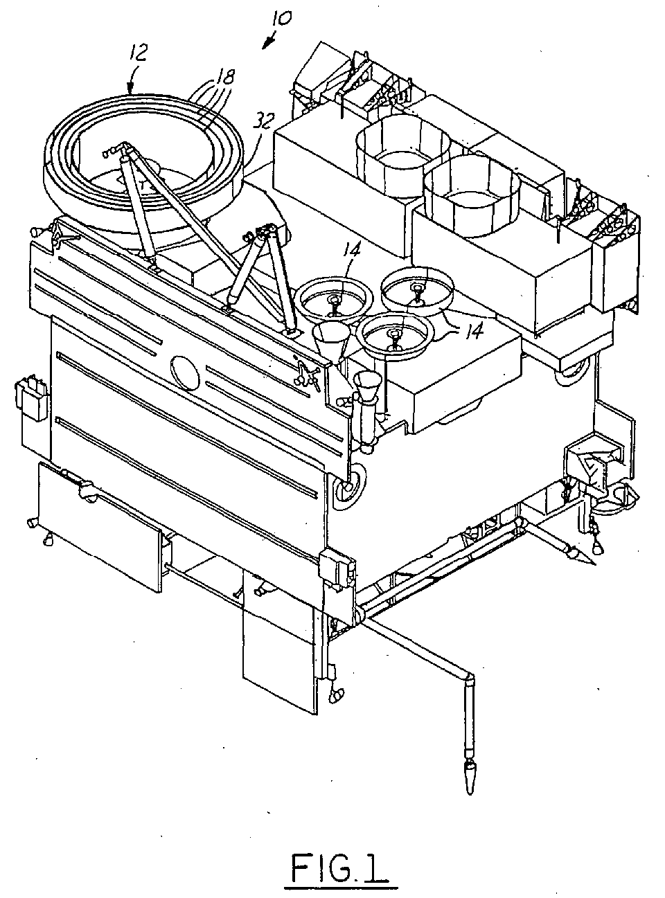
- FIGURE 1 is an illustration of an embodiment of a satellite assembly in accordance with the present invention
- FIGURE 2 is cross-sectional illustration of a portion of the satellite assembly illustrated in Figure 1;
- FIGURE 3 is a graph illustrating the null aperture field zone created by the plurality of RF chokes in accordance with the present invention.
- the satellite assembly 10 is illustrated as a GOES style satellite. Although a GOES satellite has been utilized for illustrative purposes, it should be understood that the present invention may be utilized on a wide variety of satellite assemblies and for an even wider variety of individual applications.
- the satellite assembly 10 includes an RF radiating element 12. Although a wide variety of RF radiating elements 12 are contemplated by the present invention, the RF radiating element 12 is illustrated as an aperture antenna. Electrically small aperture antennas, such as the UHF antenna commonly utilized on GOES style satellites, are known to produce RF radiation during operation. It is known that this radiation can interfere with the operation of some satellite systems and components.
- Field sensitive components 14 can be susceptible to the sidelobe RF radiation created by the RF radiating element 12, such as the GOES UHF antenna. Although a wide variety of field sensitive components 14 are contemplated by the present invention, the field sensitive components 14 illustrated in Figure 1 are intended to represent IR sounder/imagers 14 often utilized in GOES satellite designs. These IR sounder/imagers 14 are known to be sensitive to RF radiation present in the DSC downlink at 468.8 Mhz for example. Although a particular component and application sensitivity have been mentioned for illustrative purposes, it should be understood that a wide variety of specific field sensitive components 14 and application-specific sensitivities are contemplated.
- the present invention addresses this problem by reducing the sidelobe RF production at the design location of field sensitive components 14. This is accomplished through the use of a plurality of RF choke elements 18 (see Figure 2). It is contemplated that the plurality of RF choke elements 18 can comprise any number N of individual RF choke elements. Each of the plurality of RF choke elements 18 is defined by an RF dimensional set 20. Each RF dimensional set 20 includes an RF width 22 and an RF depth 24. Additional dimensional characteristics such as the RF wall thickness 25 may be utilized to define the plurality of RF choke elements 18 in addition to those described.
- the RF dimensional set 20 for each of the plurality of RF choke elements 18 are tuned such that the plurality of RF choke elements 18 work together to form a null aperture field zone 26.
- the null aperture field zone 26 is intended to represent any dimensionally or directionally defined region of the satellite assembly 10 wherein the RF sidelobe production created by the RF radiating element 12 is minimized.
- the plurality of RF choke elements 18 can be tuned as a whole such that the null aperture field zone 26 is positioned properly over the field sensitive components 14. In this fashion, an improved satellite assembly 10 is provided wherein design and packaging considerations can dictate the placement of the field sensitive components 14 rather than dictating placement by natural field minimization locations.
- the number of N of RF choke elements can also be varied to provide additional control over the positioning of the null aperture field zone 26.
- null aperture field zone 26 is intended to represent any dimensionally or directionally defined area (normally 90° from antennae bore sight) in one embodiment the null aperture field zone 26 is defined by the placement angle 28 defined by the angle from the bore sight axis of the aperture antenna 12.
- the number N of RF choke elements along with the RF width 22 and RF depth 24 can be adjusted such that the null aperture field zone 26 can be tuned to a specific angle 28 suitable for placement of the field sensitive components 14.
- Figure 3 is an illustration of a graph representing field strengths 30 in relation to placement angle 28.
- the RF dimensional sets 20 were optimized to create a null aperture field zone 26 at approximately 90 degrees. It should be understood, however, that the RF dimensional sets 20 may be tuned to optimize any angle suitable for placement of the field sensitive components.
- results illustrated in Figure 3 were taken from far-field measurements, the theory and results are equally applicable to near-field applications.
- the size of the aperture antenna 12 places size limitations on the procedure.
- the outer diameter 32 of the aperture antenna 12 is fixed.
- the number N of RF choke elements therefore, dictates the RF width 22 of each of the plurality of RF choke elements 18 when they are equally spaced.
- the RF depth 24 of each of the plurality of RF choke elements 18 is set preliminarily to a quarter wavelength in depth (i.e. a quarter wavelength of the desired suppressed wave).
- each of the plurality of RF choke elements 18 has its RF depth 24 individually adjusted until the plurality of RF choke elements 18 creates the desired null aperture field zone 26 for a specific application.
- the null aperture field zone 26 can be optimized for position and strength of reduction at the desired placement of field sensitive components 14.
Landscapes
- Physics & Mathematics (AREA)
- Engineering & Computer Science (AREA)
- Astronomy & Astrophysics (AREA)
- General Physics & Mathematics (AREA)
- Remote Sensing (AREA)
- Aviation & Aerospace Engineering (AREA)
- Variable-Direction Aerials And Aerial Arrays (AREA)
Abstract
Description
- This invention was made with Government support. The Government has certain rights in this invention.
- The present invention relates generally to an electrically small aperture antenna with field minimization capabilities, and more particularly to a satellite antenna system wherein protected devices may be placed at the null location created by the field minimized antenna.
- Satellite technology has long dictated that advancements in performance, function, and capabilities must be balanced by size and weight restrictions. This need to integrate form and function has led to a variety of advancements and continues to spur the development of further advancements. One subfield of satellite technology driven by such design characteristics has been the subfield of satellite antennae design. Multiple antennae arrays must often be utilized on a single satellite assembly in order to provide desired functionality. Size and weight restrictions on the satellite assembly often dictate that the multiple antennae arrays must be positioned within close proximity to each other. Design complications arise, however, when the proximity of such satellite arrays causes interference between individual antennae arrays and other field sensitive units within the satellite system.
- One approach towards limiting the effect of an antennae array on surrounding components has been through the use of RF chokes. RF chokes are commonly corrugations around the perimeter of the antennae aperture utilized to suppress currents from promulgating past the aperture bore sight axis. The RF chokes are commonly used to suppress side lobes by reducing the current on the backside of the antennae aperture flanges. The depth of the RF choke is commonly set near a quarter wavelength deep and the amount of side lobe reduction is commonly limited by the allowable width of the choke. Although these known configurations can reduce in side lobe reduction, they leave considerable room for improvement in interference reduction between antennae arrays and other hardware.
- Although present RF choke design is commonly configured to result in side lobe reduction, the current suppression provided by such designs commonly allow aperture fields to promulgate and cause interference with surrounding components. Sensors, receiving antennas, and imagers can all be negatively impacted by the aperture field promulgating from the antennae. Although overall reduction of the aperture field may be beneficial for the overall satellite design, specific components may require further field reduction as their mounting position on the satellite assembly. It would, therefore, be highly beneficial to have an antennae assembly whose design could be modified such that the aperture fields created by the antennae assembly could be minimized in locations where critical components are mounted. Since packaging requirements on the satellite system are often highly restrictive, such an antennae design would provide valuable placement freedom for such critical components.
- Additionally, sizing, packaging, and weight restrictions inherent in satellite design dictate that a compact antennae design capable of minimizing the aperture field in locations of critical component placement would also be highly desirable.
- It is, therefore, an object of the present invention to provide a satellite assembly including an aperture antennae configured to minimize the aperture field near a field sensitive component. It is a further object of the present invention to provide an aperture antennae with field minimization characteristics. The aperture antennae having a compact design.
- In accordance with the objects of the present invention, a satellite assembly is provided. The satellite assembly includes an aperture antennae assembly including a plurality of RF choke elements. Each of the RF chokes is defined by an RF dimensional set which includes an RF width and an RF depth. The RF dimensional sets for each of the RF chokes are varied such that the plurality of RF choke elements create a null aperture field zone. The satellite assembly further includes at least one field sensitive component positioned in the null aperture field zone.
- Other objects and features of the present invention will become apparent when viewed in light of the detailed description of the preferred embodiment when taken in conjunction with the attached drawings and appended claims.
- FIGURE 1 is an illustration of an embodiment of a satellite assembly in accordance with the present invention;
- FIGURE 2 is cross-sectional illustration of a portion of the satellite assembly illustrated in Figure 1; and
- FIGURE 3 is a graph illustrating the null aperture field zone created by the plurality of RF chokes in accordance with the present invention.
- Referring now to Figure 1, which is an illustration of a satellite assembly in accordance with the present invention. The
satellite assembly 10 is illustrated as a GOES style satellite. Although a GOES satellite has been utilized for illustrative purposes, it should be understood that the present invention may be utilized on a wide variety of satellite assemblies and for an even wider variety of individual applications. Thesatellite assembly 10 includes anRF radiating element 12. Although a wide variety ofRF radiating elements 12 are contemplated by the present invention, theRF radiating element 12 is illustrated as an aperture antenna. Electrically small aperture antennas, such as the UHF antenna commonly utilized on GOES style satellites, are known to produce RF radiation during operation. It is known that this radiation can interfere with the operation of some satellite systems and components. - One group of susceptible components are field
sensitive components 14. Fieldsensitive components 14 can be susceptible to the sidelobe RF radiation created by theRF radiating element 12, such as the GOES UHF antenna. Although a wide variety of fieldsensitive components 14 are contemplated by the present invention, the fieldsensitive components 14 illustrated in Figure 1 are intended to represent IR sounder/imagers 14 often utilized in GOES satellite designs. These IR sounder/imagers 14 are known to be sensitive to RF radiation present in the DSC downlink at 468.8 Mhz for example. Although a particular component and application sensitivity have been mentioned for illustrative purposes, it should be understood that a wide variety of specific fieldsensitive components 14 and application-specific sensitivities are contemplated. It is therefore desirable to position the fieldsensitive components 14 in a position within thesatellite assembly 10 where there is low sidelobe generation. Packaging considerations and design limitations, however, can place considerable restraints on the repositioning of such fieldsensitive components 14 into areas with naturally occurring sidelobe reductions. Furthermore, naturally occurring sidelobe reductions may be insufficient to accommodate many fieldsensitive components 14. - The present invention addresses this problem by reducing the sidelobe RF production at the design location of field
sensitive components 14. This is accomplished through the use of a plurality of RF choke elements 18 (see Figure 2). It is contemplated that the plurality ofRF choke elements 18 can comprise any number N of individual RF choke elements. Each of the plurality ofRF choke elements 18 is defined by an RFdimensional set 20. Each RFdimensional set 20 includes anRF width 22 and anRF depth 24. Additional dimensional characteristics such as the RF wall thickness 25 may be utilized to define the plurality ofRF choke elements 18 in addition to those described. The RF dimensional set 20 for each of the plurality ofRF choke elements 18 are tuned such that the plurality ofRF choke elements 18 work together to form a nullaperture field zone 26. The nullaperture field zone 26 is intended to represent any dimensionally or directionally defined region of thesatellite assembly 10 wherein the RF sidelobe production created by theRF radiating element 12 is minimized. By adjusting the RFdimensional set 20 for each of the plurality ofRF choke elements 18 independently, the plurality ofRF choke elements 18 can be tuned as a whole such that the nullaperture field zone 26 is positioned properly over the fieldsensitive components 14. In this fashion, an improvedsatellite assembly 10 is provided wherein design and packaging considerations can dictate the placement of the fieldsensitive components 14 rather than dictating placement by natural field minimization locations. In addition to modification of the RFdimensional sets 20, the number of N of RF choke elements can also be varied to provide additional control over the positioning of the nullaperture field zone 26. - Although the null
aperture field zone 26 is intended to represent any dimensionally or directionally defined area (normally 90° from antennae bore sight) in one embodiment the nullaperture field zone 26 is defined by theplacement angle 28 defined by the angle from the bore sight axis of theaperture antenna 12. The number N of RF choke elements along with theRF width 22 andRF depth 24 can be adjusted such that the nullaperture field zone 26 can be tuned to aspecific angle 28 suitable for placement of the fieldsensitive components 14. Figure 3 is an illustration of a graph representingfield strengths 30 in relation toplacement angle 28. As can be visualized, the RFdimensional sets 20 were optimized to create a nullaperture field zone 26 at approximately 90 degrees. It should be understood, however, that the RFdimensional sets 20 may be tuned to optimize any angle suitable for placement of the field sensitive components. Furthermore, although the results illustrated in Figure 3 were taken from far-field measurements, the theory and results are equally applicable to near-field applications. - Although the number N of RF choke elements and the RF
dimensional sets 20 may be adjusted in any number of fashions, in one embodiment the size of theaperture antenna 12 places size limitations on the procedure. In this particular embodiment it is contemplated that theouter diameter 32 of theaperture antenna 12 is fixed. The number N of RF choke elements, therefore, dictates theRF width 22 of each of the plurality ofRF choke elements 18 when they are equally spaced. TheRF depth 24 of each of the plurality ofRF choke elements 18 is set preliminarily to a quarter wavelength in depth (i.e. a quarter wavelength of the desired suppressed wave). Then each of the plurality ofRF choke elements 18 has itsRF depth 24 individually adjusted until the plurality ofRF choke elements 18 creates the desired nullaperture field zone 26 for a specific application. In this fashion, for a givensized aperture antenna 12, the nullaperture field zone 26 can be optimized for position and strength of reduction at the desired placement of fieldsensitive components 14. - While particular embodiments of the invention have been shown and described, numerous variations and alternative embodiments will occur to those skilled in the art. Accordingly, it is intended that the invention be limited only in terms of the appended claims.
Claims (15)
- A satellite assembly comprising:an RF radiating element (12) including a plurality of RF choke elements (18), each of said plurality of RF choke elements (18) being defined by an RF dimensional set (20) including an RF depth (24) and an RF width (22);a null aperture field zone (26) created by said plurality of RF choke elements (18); said null aperture field zone (26) created by tuning each of said RF dimensional sets (20); andat least one field sensitive component (14) positioned within said null aperture field zone (26).
- A satellite assembly as described in claim 1, wherein said RF radiating element (12) is an aperture antenna including a number N of RF choke elements (18); and said null aperture field zone (26) is adjusted by the quantity of said number N of RF choke elements (18) and by tuning each of said RF dimensional sets (20).
- A satellite assembly as described in claim 1 or 2, wherein said tuning each of said RF dimensional sets (20) comprises adjusting each of said RF depths (24).
- A satellite assembly as described in any of claims 1-3, wherein said tuning each of said RF dimensional sets (20) comprises adjusting each of said RF widths (22).
- A satellite assembly as described in any of claims 1 - 4, wherein said RF dimensional set (20) includes an RF wall thickness (25), and wherein said tuning of each of said RF dimensional sets (20) comprises adjusting each of said RF wall thicknesses (25).
- A satellite assembly as described in any of claims 1 - 5, wherein the number of said plurality of RF choke elements (18) is adjusted to create said null aperture field zone (26).
- A satellite assembly as described in any of claims 1 - 6, wherein each of said RF widths (22) is a function of the number of said plurality of RF choke elements (18).
- A satellite assembly as described in any of claims 1 - 7, wherein said null aperture field zone (26) is defined by the placement angle (28) of said at least one field sensitive component (14) relative to said RF radiating element (12).
- A satellite assembly as described in claim 1, wherein said RF radiating element (12) is an aperture antenna.
- A satellite assembly as described in any of claims 1 - 9, wherein said RF radiating element (12) is a UHF antenna.
- A satellite assembly as described in any of claims 1 - 10, wherein said at least one field sensitive component (14) comprises at least one IR sounder/imager (14).
- A satellite assembly as described in claim 2, wherein each of said RF depths (24) is set to a quarter wavelength prior to tuning.
- A method of reducing the effects an RF radiating element, including a plurality of RF choke elements (18), on a field sensitive component (14) comprising:tuning the RF depth (24) of each of said plurality of RF choke elements (18) such that the plurality of RF choke elements (18) create a null aperture field zone (26) that coincides with the placement of a field sensitive component (14).
- A method as described in claim 13, further comprising:adjusting the number of said plurality of RF choke elements (18) such that said null aperture field zone (26) coincides with the placement of said field sensitive component (14).
- A method as described in claim 13 or 14, further comprising:tuning the RF width (22) of each of said plurality of RF choke elements (18) such that the plurality of RF choke elements (18) create a null aperture field zone (26) that coincides with the placement of a field sensitive component.
Applications Claiming Priority (2)
| Application Number | Priority Date | Filing Date | Title |
|---|---|---|---|
| US10/170,119 US6618021B1 (en) | 2002-06-12 | 2002-06-12 | Electrically small aperture antennae with field minimization |
| US170119 | 2002-06-12 |
Publications (2)
| Publication Number | Publication Date |
|---|---|
| EP1372217A2 true EP1372217A2 (en) | 2003-12-17 |
| EP1372217A3 EP1372217A3 (en) | 2004-03-17 |
Family
ID=27788626
Family Applications (1)
| Application Number | Title | Priority Date | Filing Date |
|---|---|---|---|
| EP03013166A Ceased EP1372217A3 (en) | 2002-06-12 | 2003-06-11 | Electrically small aperture antennae with field minimization |
Country Status (2)
| Country | Link |
|---|---|
| US (1) | US6618021B1 (en) |
| EP (1) | EP1372217A3 (en) |
Families Citing this family (1)
| Publication number | Priority date | Publication date | Assignee | Title |
|---|---|---|---|---|
| US20130076583A1 (en) * | 2011-09-23 | 2013-03-28 | Microelectronics Technology, Inc. | Multiple feed antenna operating at significantly differing frequencies |
Citations (6)
| Publication number | Priority date | Publication date | Assignee | Title |
|---|---|---|---|---|
| SU1483509A1 (en) * | 1987-04-16 | 1989-05-30 | Одесский Электротехнический Институт Связи Им.А.С.Попова | Aerial decoupling device |
| US5132698A (en) * | 1991-08-26 | 1992-07-21 | Trw Inc. | Choke-slot ground plane and antenna system |
| US5461394A (en) * | 1992-02-24 | 1995-10-24 | Chaparral Communications Inc. | Dual band signal receiver |
| EP1037305A2 (en) * | 1999-03-16 | 2000-09-20 | TRW Inc. | Dual depth aperture chokes for dual frequency horn equalizing E and H-plane patterns |
| US6222492B1 (en) * | 1994-05-09 | 2001-04-24 | Optim Microwave, Inc. | Dual coaxial feed for tracking antenna |
| US6407722B1 (en) * | 2001-03-09 | 2002-06-18 | Lockheed Martin Corporation | Choke coupled coaxial connector |
Family Cites Families (4)
| Publication number | Priority date | Publication date | Assignee | Title |
|---|---|---|---|---|
| US2455888A (en) * | 1944-08-12 | 1948-12-07 | Rca Corp | Antenna |
| GB8922377D0 (en) * | 1989-10-04 | 1990-06-20 | Marconi Co Ltd | Microwave antenna |
| US5552797A (en) * | 1994-12-02 | 1996-09-03 | Avnet, Inc. | Die-castable corrugated horns providing elliptical beams |
| US6208310B1 (en) * | 1999-07-13 | 2001-03-27 | Trw Inc. | Multimode choked antenna feed horn |
-
2002
- 2002-06-12 US US10/170,119 patent/US6618021B1/en not_active Expired - Lifetime
-
2003
- 2003-06-11 EP EP03013166A patent/EP1372217A3/en not_active Ceased
Patent Citations (6)
| Publication number | Priority date | Publication date | Assignee | Title |
|---|---|---|---|---|
| SU1483509A1 (en) * | 1987-04-16 | 1989-05-30 | Одесский Электротехнический Институт Связи Им.А.С.Попова | Aerial decoupling device |
| US5132698A (en) * | 1991-08-26 | 1992-07-21 | Trw Inc. | Choke-slot ground plane and antenna system |
| US5461394A (en) * | 1992-02-24 | 1995-10-24 | Chaparral Communications Inc. | Dual band signal receiver |
| US6222492B1 (en) * | 1994-05-09 | 2001-04-24 | Optim Microwave, Inc. | Dual coaxial feed for tracking antenna |
| EP1037305A2 (en) * | 1999-03-16 | 2000-09-20 | TRW Inc. | Dual depth aperture chokes for dual frequency horn equalizing E and H-plane patterns |
| US6407722B1 (en) * | 2001-03-09 | 2002-06-18 | Lockheed Martin Corporation | Choke coupled coaxial connector |
Non-Patent Citations (2)
| Title |
|---|
| BRACHAT P: "SECTORAL PATTERN SYNTHESIS WITH PRIMARY FEEDS", IEEE TRANSACTIONS ON ANTENNAS AND PROPAGATION, IEEE SERVICE CENTER, PISCATAWAY, NJ, US, vol. 42, no. 4, 1 April 1994 (1994-04-01), pages 484 - 491, XP000450162, ISSN: 0018-926X, DOI: 10.1109/8.286216 * |
| GARCÍA-MÜLLER P L: "Optimisation of compact horn with broad sectoral radiation pattern", ELECTRONICS LETTERS, IEE STEVENAGE, GB, vol. 37, no. 6, 15 March 2001 (2001-03-15), pages 337 - 338, XP006016389, ISSN: 0013-5194, DOI: 10.1049/EL:20010268 * |
Also Published As
| Publication number | Publication date |
|---|---|
| US6618021B1 (en) | 2003-09-09 |
| EP1372217A3 (en) | 2004-03-17 |
Similar Documents
| Publication | Publication Date | Title |
|---|---|---|
| US7456797B2 (en) | Antenna system with parasitic element and associated method | |
| US5400040A (en) | Microstrip patch antenna | |
| US5654724A (en) | Antenna providing hemispherical omnidirectional coverage | |
| EP2281324A1 (en) | Small aperture interrogator antenna system employing sum-difference azimuth discrimination techniques | |
| WO2003043351A3 (en) | Co-located antenna array for passive beam forming | |
| EP3480886B1 (en) | Wireless receiving/transmitting device and base station | |
| US20180241121A1 (en) | Radio frequency chokes for integrated phased-array antennas | |
| US6323817B1 (en) | Antenna cluster configuration for wide-angle coverage | |
| KR102597567B1 (en) | Shared aperture antenna system having a mesh net | |
| US6611238B1 (en) | Method and apparatus for reducing earth station interference from non-GSO and terrestrial sources | |
| US5657032A (en) | Aircraft cellular communications antenna | |
| US6384795B1 (en) | Multi-step circular horn system | |
| EP0386224A4 (en) | Data processing system for a phased array antenna | |
| US6618021B1 (en) | Electrically small aperture antennae with field minimization | |
| US5977926A (en) | Multi-focus reflector antenna | |
| KR20210073827A (en) | Wide Angle Array Antenna using a Parasitic Ring Structure | |
| JP4724862B2 (en) | Array antenna | |
| US7579995B1 (en) | Near field nulling antenna systems | |
| EP0805515A3 (en) | Antenna cross-polar suppression means | |
| CA2064295C (en) | Microwave polarizing lens structure | |
| US12542377B2 (en) | Satellite platform and method for reconfiguring the electromagnetic beam of such a satellite platform | |
| US5877729A (en) | Wide-beam high gain base station communications antenna | |
| JP4697595B2 (en) | Embedded ceiling antenna | |
| CN113451748A (en) | Yagi-uda antenna and aircraft including yagi-uda antenna | |
| CN119601982B (en) | A wideband airspace radiation device and a wide airspace anti-unmanned system |
Legal Events
| Date | Code | Title | Description |
|---|---|---|---|
| PUAI | Public reference made under article 153(3) epc to a published international application that has entered the european phase |
Free format text: ORIGINAL CODE: 0009012 |
|
| AK | Designated contracting states |
Kind code of ref document: A2 Designated state(s): AT BE BG CH CY CZ DE DK EE ES FI FR GB GR HU IE IT LI LU MC NL PT RO SE SI SK TR |
|
| AX | Request for extension of the european patent |
Extension state: AL LT LV MK |
|
| PUAL | Search report despatched |
Free format text: ORIGINAL CODE: 0009013 |
|
| AK | Designated contracting states |
Kind code of ref document: A3 Designated state(s): AT BE BG CH CY CZ DE DK EE ES FI FR GB GR HU IE IT LI LU MC NL PT RO SE SI SK TR |
|
| AX | Request for extension of the european patent |
Extension state: AL LT LV MK |
|
| RIC1 | Information provided on ipc code assigned before grant |
Ipc: 7H 01Q 13/28 B Ipc: 7H 01Q 1/52 B Ipc: 7H 01Q 13/02 A |
|
| 17P | Request for examination filed |
Effective date: 20040818 |
|
| AKX | Designation fees paid |
Designated state(s): DE FR IT |
|
| 17Q | First examination report despatched |
Effective date: 20070914 |
|
| APBK | Appeal reference recorded |
Free format text: ORIGINAL CODE: EPIDOSNREFNE |
|
| APBN | Date of receipt of notice of appeal recorded |
Free format text: ORIGINAL CODE: EPIDOSNNOA2E |
|
| APBR | Date of receipt of statement of grounds of appeal recorded |
Free format text: ORIGINAL CODE: EPIDOSNNOA3E |
|
| APAF | Appeal reference modified |
Free format text: ORIGINAL CODE: EPIDOSCREFNE |
|
| APBT | Appeal procedure closed |
Free format text: ORIGINAL CODE: EPIDOSNNOA9E |
|
| STAA | Information on the status of an ep patent application or granted ep patent |
Free format text: STATUS: THE APPLICATION HAS BEEN REFUSED |
|
| 18R | Application refused |
Effective date: 20201201 |