The present invention relates to the field of photosensitive element
based photography and more particularly to a method and apparatii for using a
photosensitive element that is photosensitive to light within a predetermined range
of exposure levels to capture images including exposure levels that are outside the
predetermined range.
In conventional photography, it is well known to record images by
controllably exposing a photosensitive element to light from a scene. Typically,
such a photosensitive element comprises one or more photosensitive layers
supported by a flexible substrate such as film and/or a non-flexible substrate such
as a glass plate. The photosensitive layers, which can have one or more light
sensitive silver halide emulsions along with product appropriate imaging
chemistry, react to the energy provided by the light from the scene. The extent of
this reaction is a function of the amount of light received per unit area of the
element during exposure. The extent of this reaction is greater in areas of the
element that are exposed to more light during an exposure than in areas that are
exposed to less light. Thus, when light from the scene is focused onto a
photosensitive element, differences in the levels of light from the scene are
captured as differences in the extent of the reaction in the layers. After a
development step, the differences in the extent of the reaction in the layers appear
as picture regions having different densities. These densities form an image of the
original scene luminance.
It is characteristic of silver halide emulsions to have a non-linear
response when exposed to ambient light from a scene. In this regard a
photosensitive element has a lower response threshold that defines the minimum
exposure at which the incorporated emulsions and associated chemistry begins to
react so that different levels of exposure enable the formation of different
densities. This lower threshold ultimately relates to the quantum efficiency of
individual silver halide emulsion grains. Typically, all portions of a
photosensitive element that are exposed to light at a level below the lower
response threshold have a common appearance when the photosensitive element is
developed.
Further, a photosensitive element also has an upper response
threshold that defines the exposure level below which the emulsion and associated
chemistries react so that different levels of exposure enable the formation of
different densities. Typically, all portions of an element that are exposed at a level
above the upper response threshold will again have a common appearance after
the photosensitive element is developed.
Thus photosensitive elements that use silver halide emulsions can
be said to have both a lower response threshold and an upper response threshold
which bracket a useful range of exposures wherein the photosensitive element is
capable of reacting to differences in exposure levels by recording a contrast
pattern with contrast differences that are differentiable. The exposure levels
associated with these lower and upper thresholds define the exposure latitude of
the photosensitive element. To optimize the appearance of an image, therefore, it
is typically useful to arrange the exposure so that the range of exposure levels
encountered by the photosensitive element during exposure is within the latitude
or useful range of the photosensitive element.
Many consumer and professional photographers prefer to use
photosensitive elements, camera systems, and photography methods that permit
image capture over a wide range of photographic conditions. One approach to
meeting this objective is to provide photosensitive elements with extremely wide
latitude. However, extremely wide latitude photosensitive elements are
fundamentally limited by the nature of the response of the individually
incorporated silver halide grains to light. Accordingly, it is common to provide
camera systems and photography methods that work to effectively extend the
lower response limit and upper response limit of a photosensitive element by
modifying the luminance characteristics of the scene. For example, it is known to
effectively extend the lower response limit of the photosensitive element by
providing supplemental illumination to dark scenes.
It is also known to increase the quantity of the light acting on a
photosensitive element without providing supplemental illumination by using a
taking lens system designed to pass a substantial amount of the available light
from the scene to the photosensitive element during an exposure. However, lenses
that pass a substantial amount of light also inherently reduce the depth-of field of
the associated camera system. This solution is thus not universally suitable for
pictorial imaging with fixed focus cameras since scenes may not then be properly
focused. This solution is also not preferred in variable focused cameras as such
lens systems can be expensive, and difficult to design, install and maintain.
There is a direct relationship between the duration of exposure and
quantity of light from the scene that strikes the photosensitive element during an
exposure. Accordingly, another way known in the art for increasing the amount
of light acting on a photosensitive element during an exposure is to increase the
duration of the exposure using the expedient of a longer open shutter. This,
however, degrades upper exposure limits. Further, increased shutter open time
can cause the shutter to remain open for a period that is long enough to permit the
composition of a scene to evolve. This results in a blurred image. Accordingly,
there is a desire to limit shutter open time.
Thus, what is also needed is a less complex and less costly camera
system and photography method allowing the capture of images using
conventional shutter open times and particularly with cameras having a fixed
shutter time.
Another way to increase the quantity of the light acting on a
photosensitive element during an exposure is to use a conventional taking lens
system to collect light from a scene and to project this light from the scene onto an
array of micro-lenses such as an array of linear lenticular lenses that are located
proximate to the photosensitive element. An example of this is shown in Chretien
U.S. Pat. No. 1,838,173. Each micro-lens concentrates a portion of the light from
the scene onto associated areas of a photosensitive element. By concentrating
light in this manner, the amount of light incident on each concentrated exposure
area of the photosensitive element is increased to a level that is above the lower
response threshold of the film. This permits an image to be formed by contrast
patterns in the densities of the concentrated exposure areas.
Images formed in this manner are segmented: the concentrated exposure
areas form a concentrated image of the scene and remaining portions of the
photosensitive element form a pattern of unexposed artifacts intermingled with the
concentrated image. In conventionally rendered prints of such images this pattern
has an unpleasing low contrast and a half-tone look much like newspaper print.
However, a recognizable image can be obtained from such
segmented images by projection under quite specific conditions. These conditions
occur precisely when the spatial relationship between the effective camera
aperture, the micro-lens array and the light sensitive element established at
exposure in the camera is reproduced in the projector. This system can be
cumbersome because a functional real image is produced at a position and
magnification dictated by the original scene to camera lens arrangement. If a
projection lens identical to the camera taking lens is positioned so as to mimic the
camera lens to image relationship that existed at image taking, the reconstructed
image will appear at the position of the original object with the size of the original
object. Other lens and spatial relationship combinations result in incomplete
image reconstruction and the formation of the dots and lines reminiscent of
newspaper print. Thus, the micro-lens or lenticular assisted low light photography
of the prior art is ill suited for the production of prints or for use in high quality
markets such as those represented by consumers and professional photographers.
Micro-lens arrays, and in particular, lenticular arrays have found
other applications in photography. For example, in the early days of color
photography, linear lenticular image capture was used in combination with color
filters as means for splitting the color spectrum to allow for color photography
using black and white silver halide imaging systems. This technology was
commercially employed in early color motion picture capture and projection
systems as is described in commonly assigned U.S. Pat. No. 2,191,038. In the
1940s it was proposed to use lenticular screens to help capture color images using
black and white photosensitive element in instant photography U.S. Pat. No.
2,922,103. In the 1970's, U.S. Pat. No. 4,272,186 disclosed the use of lenticular
arrays to create images having increased contrast characteristics. By minimizing
the size of the unexposed areas, the line pattern became almost invisible and was
therefore less objectionable. Also in the 1970s, it was proposed to expose
photosensitive element through a moving lenticular screen U.S. Pat. No.
3,954,334. Finally, in the 1990's linear lenticular-ridged supports having three-color
layers and an antihalation layer were employed for 3-D image presentation
materials. These linear lenticular arrays were used to form interleaved print
images from multiple views of a scene captured in multiple lens camera. The
interleaved images providing a three dimensional appearance. Examples of this
technique are disclosed by Lo et al. in U.S. Pat No. 5,464,128 and by Ip, in U.S.
Pat. No. 5,744,291. It is recognized that these disclosures relate to methods,
elements and apparatus adapted to the formation of 3-D images from capture of
multiple scene perspectives that are suitable for direct viewing. They fail to
enable photography with shutter times suitable for use in hand-held cameras.
Thus, while micro-lens assisted photography has found a variety of
uses, it has yet to fulfill the original promise of effectively extending the lower
response threshold of a photosensitive element to permit the production of
commercially acceptable prints from images captured at low scene brightness
levels. What is needed, therefore, is a method and apparatus for capturing
lenticular images on a photosensitive element and using the captured
photosensitive element image to form a commercially acceptable print or other
output.
It can also occur that it is useful to capture images under imaging
conditions that are above the upper response threshold of the photosensitive
element. Such conditions can occur with bright scenes that are to be captured
under daylight, snow pack and beach situations. Typically, cameras use aperture
control, shutter timing control and filtering systems to reduce the intensity of light
from the scene so that the light that confronts the photosensitive element has an
intensity that is within the upper limit response of the photosensitive element.
However, these systems can add significant complexity and cost to the design of
the camera. Further, the expedient of using a lens with a more open aperture to
improve the lower threshold limit as discussed earlier simultaneously passes more
light and degrades the exposure at the upper response threshold. Thus, what is
also needed is a simple, less costly, camera system and photography method for
capturing images over a range of exposure levels including exposure levels that
are greater than the upper response limit of the photosensitive element.
According to a feature of the present invention a method is
provided for using a photosensitive element that is photosensitive to light within a
predetermined range of exposures to capture images including exposures that are
outside of the predetermined range of exposures. In this method the
photosensitive element is exposed to light from the scene. The light from the
scene is fractured into concentrated portions and residual portions with the
concentrated portions directed at concentrated images areas of the photosensitive
element to form a pattern of concentrated image elements providing a
concentrated image when light from the scene is within a first exposure range.
The residual portions of the light are directed at a residual image area of the
photosensitive element and form an image in the residual image area when light
from the scene is within a second exposure range. Wherein the combination of
the first range and second range is greater than the predetermined range of
exposures.
This invention is related to photography systems and photography
methods that extend the effective image capture latitude of a photosensitive
element.
IMAGE CAPTURE
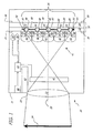
Fig. 1 shows a diagram useful in describing the operation of one
embodiment of a camera 20 for forming an image on a photosensitive element 30
comprising a photosensitive layer 32 and a substrate 34. In the embodiment of
Fig. 1, camera 20 includes a body 21 having an aperture 23 to admit light from a
scene 24 into body 21. A taking lens system 22 directs light from a scene 24
along optical axis 25 toward a gate 26 that positions photosensitive element 30 at
a defined distance from taking lens system 22 during exposure. In the
embodiment shown, taking lens system 22 is located at aperture 23. Preferably,
the depth of focus of the photosensitive element 30 plus taking lens system 22 is
such that an image 24' is formed on an imaging area 36 of the photosensitive layer
32 with scene 24' having a consistent focus across the imaging area 36.
Interposed between taking lens system 22 and photosensitive
element 30 is a micro-lens array 40 having a plurality of micro-lenses 42. Each of
the micro-lenses 42 in micro-lens array 40 receives a portion of the light passing
from the taking lens system 22 and fractures this light into a concentrated fraction
44 and a residual fraction 46. Each of the concentrated fractions 44 are
concentrated onto associated concentrated image areas 48 of photosensitive
element 30 and each residual fraction 46 passes to an associated residual image
area 50 of photosensitive element 30. The effect of fracturing is shown
conceptually in Fig. 1 and will now be described with reference to Figs. 1 and 2a,
2b and 2c. A shutter system 27 is disposed between aperture 23 and micro-lens
array 40. Shutter system 27 controllably permits light from the scene to expose
photosensitive element 30 for a predefined period of time.
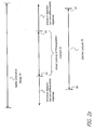
As is shown in Fig. 2a, light from a photographic scene extends,
over a wide range of scene luminances. In the case of consumer photography,
these are the luminances that are visually observable by humans. This range is
indicated in Fig. 2a as scene luminance range 70. However, photosensitive
element 30 has an actual latitude 72 within which the photosensitive element 30
can capture differences in scene illumination and record a contrast image of the
scene. Because of the inherent limitations of chemical image capture technology
and the specific non-linear response of the photosensitive element 30 to
illumination from the scene, the actual latitude 72 of photosensitive element 30 is
defined by a lower response threshold 74 and an upper response threshold 76.
Photosensitive element 30 does not differentiably react to scene illumination
differences when element 30 is exposed to quantities of light that are lower than
the lower response threshold 74. As noted above, this is because the energy made
available by such limited quantities of light is not sufficient to cause the emulsion
to react to form a differentiable exposure record. Accordingly, all portions of
photosensitive element 30 that are exposed to such quantities of light have a
generally light appearance when photosensitive element 30 is photoprocessed.
Similarly, photosensitive element 30 does not differentiably react
to scene illumination differences when element 30 is exposed to quantities of light
that are higher than the upper response threshold 76. As noted in greater detail
above, this is because the amount of light received by photosensitive element 30
above upper response threshold 76 is sufficient to drive the chemical reaction of
the emulsion to a point wherein photosensitive element 30 no longer has a
meaningful additional density response to additional light energy. Because of
this, all portions of photosensitive element 30 that are exposed to such quantities
of light have a generally dark appearance when the photosensitive element 30 is
photoprocessed.
It is appreciated that the terms light and dark are appropriate for
negative working photosensitive materials such as print films intended for use
with negative working papers or for scanning. In positive working photosensitive
materials such as reversal slide films and direct print films, the recited areas would
be respectively dark and light in character.
Any known photosensitive material formulation can be used to
prepare a photosensitive element 30 useful in the practice of the invention.
Elements having excellent light sensitivity are best employed in the practice of
this invention. The elements should have a sensitivity of at least about ISO 25, a
sensitivity of at least about ISO 100, and more preferably have a sensitivity of at
least about ISO 400. The speed, or sensitivity, of a color negative photographic
element is inversely related to the exposure required to enable the attainment of a
specified density above fog after processing. Photographic speed for a color
negative element with a gamma of about 0.65 in each color record has been
specifically defined by the American National Standards Institute (ANSI) as ANSI
Standard Number pH 2.27-1981 (ISO (ASA Speed)) and relates specifically the
average of exposure levels required to produce a density of 0.15 above the
minimum density in each of the green light sensitive and least sensitive color
recording unit of a color film. This definition conforms to the International
Standards Organization (ISO) film speed rating. For the purposes of this
application, if the color unit gammas differ from 0.65, the ASA or ISO speed is to
be calculated by linearly amplifying or deamplifying the gamma vs. log E
(exposure) curve to a value of 0.65 before determining the speed in the otherwise
defined manner.
While standard photographic elements can be employed in this
invention, the elements most useful in this invention are designed for capturing an
image in machine readable form rather than in a form suitable for direct viewing.
In the capture element, speed (the sensitivity of the element to low light
conditions) is usually critical to obtaining sufficient image in such elements.
Accordingly, the elements, after micro-lens speed enhancement will typically
exhibit an equivalent ISO speed of 800 or greater, preferable an equivalent ISO
speed of 1600 or greater and most preferably an equivalent ISO speed of 3200 or
greater. The elements will have a latitude of at least 3.0 log E, and preferably a
latitude of 4.0 log E, and more preferable a latitude of 5.0 log E or even higher in
each color record. Such a high useful latitude dictates that the gamma of each
color record (i.e. the slope of the Density vs. log E after photoprocessing) be less
than 0.70, preferably less than 0.60, more preferably less than 0.50 and most
preferably less than 0.45. Further, the color interactions between or interimage
effects are preferably minimized. This minimization of interimage effect can be
achieved by minimizing the quantity of masking couplers and DIR compounds.
The interimage effect can be quantified as the ratio of the gamma of a particular
color record after a color separation exposure and photoprocessing divided by the
gamma of the same color record after a white light exposure. The gamma ratio of
each color record is preferably between 0.8 and 1.2, more preferably between 0.9
and 1.1 and most preferably between 0.95 and 1.05. Further details of the
construction, characteristic quantification of the performance of such scan enabled
light sensitive elements are disclosed in Sowinski et al. U. S. Pat. Nos. 6,021,277
and 6,190,847.
However, as is also shown in Fig. 2a, it is desirable that camera 20
and photosensitive element 30 should record scene information at a lower
response threshold 80 that is lower than the lower response threshold 74 of
photosensitive element 30 as is shown in Fig. 2a. In accordance with the
principles of the present invention, photography in this range of illumination is
made possible by concentrating light from the scene. In this regard, each of the
micro-lenses 42 in array 40 fractures light from the scene into at least two
portions. As is shown in Fig. 1, a concentrated fraction 44 of light from scene 24
is concentrated so that a greater amount of light per unit area falls upon each of
the concentrated image areas 48 of photosensitive element 30 during an exposure
than would fall upon concentrated image areas 48 in the absence of the array 40 of
micro-lenses 42. As is shown in Fig. 2b, this increase in the amount of light
incident upon concentrated image areas 48 has the effect of shifting a first range
84 of scene exposure levels so that the entire first range 84 is within actual film
latitude 72 allowing a pattern of concentrated image elements 52 to form a
contrast image in the concentrated image areas 48 of photosensitive element 30.
Incidentally, some of the light incident on micro-lenses 42, for
example light that is poorly focused by micro-lenses 42 or light that passes
between distinct ones of micro-lenses 42, is not concentrated. Instead, this
residual fraction 46 of the light passes to photosensitive element 30 and is incident
on residual image area 50 enabling formation of a residual image 54. Residual
image 54 can further be formed by designed or adventitious light scatter and
reflection in photosensitive element 20. This residual fraction of light 46 is less
than the amount of light that would be incident on photosensitive element 30 in
the event that array 40 of micro-lenses 42 was not interposed between the scene
24 and the photosensitive element 30 during the same exposure. Thus, micro-lenses
42 effectively filter light from the scene that is incident on residual image
area 50 so that a greater quantity of light must be available during the exposure in
order for a residual image 54 to be formed on photosensitive element 30.
Accordingly, the predefined period of time that shutter system 27
permits for exposure of photosensitive element 30 is sufficient to form an image
on the residual image area 50 of the photosensitive element when light from the
scene is within a second range.
Accordingly, as is shown in Fig. 2c, when the micro-lenses 42 of
array 40 are exposed to light within a second exposure range 86, a second
exposure suitable for producing an image over the range indicated by second
image range 86 is formed on photosensitive element 30 in the residual image area
50. In this way, photosensitive element 30 can be used to record differentiable
images at exposure levels that are above the upper response threshold 76 of
photosensitive element 30 but below upper response threshold 82.
A region of overlap can be defined between first exposure range 84
and second exposure range 86. Where it is desired to greatly increase system
latitude 78 of the photosensitive element 30, this region of overlap can be
contracted. In one embodiment, the ability to capture image information from
either of the concentrated image elements 52 or residual image 54 over a
continuous system latitude 78 is ensured by defining a substantial range of
exposures wherein first exposure range 84 and second exposure range 86 overlap.
Alternatively, it may be preferred to provide a camera 20 wherein there is
substantial separation between first exposure range 84 and second exposure range
86. Camera 20 having such a substantial separation would effectively operate to
capture different images under very different imaging conditions such as daylight
and interior light.
It will be appreciated that when an exposure level is in the second
exposure range 86, concentrated image elements 52 are formed on element 30.
The concentrated image elements 52 formed during exposure in the second
exposure range 86 can contain useful imaging information where the first
exposure range 84 and second exposure range 86 at least partially overlap.
However, where the exposure is above the first exposure range 84 then the
concentrated image elements 52 will appear as over exposed artifacts in the image
formed in the residual image area 50.
It will be further appreciated that while this discussion has been
framed in terms of a specific embodiment directed towards silver halide
photography intended for capturing human visible scenes the invention can be
readily applied to capture extended scene luminance ranges and spectral regions
invisible to humans and the light sensitive material can be any light sensitive
material known to the art that has the requisite imaging characteristics. The
effective increase in latitude enabled can be at least 0.15 log E. In certain
embodiments, the effective increase in latitude can be between at least 0.3 log E
and 0.6 log E. Preferably, the effective increase in latitude is at least 0.9 log E.
FORMING AN IMAGE USING CONCENTRATED IMAGE ELEMENTS
Fig. 3 shows a flow diagram of one embodiment of a method for
using a photosensitive element 30 having a fixed exposure range to capture image
information from scenes having a different exposure ranges and for recovering an
acceptable output image from the imaging information recorded on the
photosensitive element 30. The first step in this process is that of exposing the
photosensitive element to light from a scene. (step 100).
The light is fractured into a pattern of concentrated fractions and
residual fractions. (step 102) As described above, the concentrated fractions of
the light form a pattern of concentrated imaging elements 52 such as lines or dots
on photosensitive element 30 after development. When the light from the scene
is within first exposure range 84 a contrast image is formed in the concentrated
image elements 52. As is also described above, the residual fractions of the light
expose a residual image area 50 of the photosensitive element 30. When light
from the scene is within second exposure range 86, a contrast image is formed on
the photosensitive element 30. Preferably, the first exposure range 84 and second
exposure range 86 together are greater than the latitude of the photosensitive
element 30.
The photosensitive element 30 is then photoprocessed (step 104).
Any art known for photoprocessing can be employed. The photoprocessing can
comprise a development step with optional desilvering steps. The
photoprocessing can be done by contacting the photosensitive element with
photoprocessing chemicals or known agents enabling photoprocessing. The
photoprocessing can be done by contacting the photosensitive element 30 with
aqueous solutions of photoprocessing chemicals or pH adjusting agents or both.
Alternatively, the photosensitive element can be photoprocessed using an art
known as photothermographic processing wherein the photosensitive element 30
is photoprocessed by heating or by a combination of contacting with
photoprocessing enabling agents and heat. As a result of photoprocessing (step
104) photosensitive element 30 becomes a photoprocessed element 38 having at
least one image wise contrast image recorded thereon.
Photoprocessed element 38 is scanned (step 108) and the scanned
image is processed (step 110) to recover an output image based upon image data
from either or both of the concentrated image areas 44 or the residual image areas
50. It will be appreciated that the scanning and processing steps can be expedited
where it is known whether photoprocessed element 38 contains imaging
information in the first area only or in both the first and second areas. Thus in the
embodiment of Fig. 3, the step of determining where imaging information can be
found (step 106) is performed before scanning (step 108). The output image is
optionally further improved (block 112) and processed for its intended use (step
114). The output image is then delivered. (step 116)
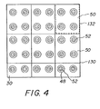
Referring again to Fig. 4 what is shown is an image pattern formed
on a photoprocessed element 38 after the steps of exposure (step 100) fracture
(step 102) and photoprocessing (step 104) have been performed. The image
pattern formed on photoprocessed element 38 represents an image pattern that is
formed when the scene has a range of exposure levels that is within the first
exposure range 84 but lower than the second exposure range 86. Accordingly, on
the photoprocessed element 38 shown in Fig. 4, exposure forms a pattern of
concentrated image elements 52 while no exposure occurs in the residual image
area 50. As is shown in Fig. 4, concentrated image areas 48 have a dot shaped
concentrated image element 52. Each dot shaped concentrated image element 52
has a density that is related to original scene exposure. Accordingly, an image of
the scene can be derived from contrast differences between the dot shaped
concentrated image element 52.
In the embodiment of Figs.1-3, the pattern of dot shaped
concentrated image element 52 are formed by passing light from scene 24 through
a micro-lens array 40 comprising a cubic, close packed lenticular array of circular
micro-lenses 42. This arrangement results in the dot pattern shown in Fig. 4. In
this embodiment, micro-lenses 42 can have a uniform cross-sectional area. Fig.
5a shows, conceptually, a micro-lens array 40, of micro-lenses 42 arranged in a
uniform cubic close packed distribution pattern by a support 90. It will be
appreciated that other array patterns can be used. For example, Fig. 5b shows an
embodiment having an off-set square close packed array pattern. In another
embodiment shown in Fig. 5c micro-lenses 42 are arranged in micro-lens array 40
having a hexagonal close packed array pattern. Micro-lens array 40 can also
feature random distributions of micro-lenses 42. One embodiment of an array
having a random distribution is shown in Fig. 5d. As is shown in Fig. 5e, in still
another embodiment, micro-lens array 40 can comprise an array of cylindrical or
acylindrical micro-lenses 42.
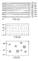
As is shown in Figs. 6a, 6b and 6c, micro-lens array 40 can
comprise micro-lenses 42 having different optical characteristics. In the
embodiment of Fig. 6a, a micro-lens array 40 of cylindrical micro-lenses 42 is
shown. As is shown in Fig. 6a, micro-lens array 40 has a first set of micro-lenses
42a that have a greater cross-section area than a second set of micro-lenses 42b
also provided by micro-lens array 40. In this embodiment, the first set of micro-lenses
42a concentrate a greater portion of light during an exposure than micro-lenses
42b. Thus, the first set of micro-lenses 42a form a line image on
photosensitive element 30 as shown in Fig. 6d, in a first set of concentrated image
areas 48a, when the amount of the light during the exposure is within a first
exposure range 84. When a light from the scene within a second exposure range
86, the second set of micro-lens array 42b form a line image on photosensitive
element 30 in a second set of concentrated image areas 48b. Light that is not
concentrated by either set of micro-lenses 42a and 42b can form a residual image
(not shown) in residual image area 50 of photosensitive element 30 of Fig. 6d.
Similarly, Figs. 6b and 6c each show the use of a micro-lens array 40 having
differently sized sets of micro-lenses 42a and 42b with the micro-lens array 40a
concentrating light to form an exposure and directing that light onto concentrated
image areas 48a on photosensitive element 30 when light from scene 24 is within
a fist range. Micro-lenses 40b concentrate light from a scene and direct this light
onto concentrated image areas 48b on photosensitive element 30 to form an
exposure when the light from the scene is within a second range. Here too,
residual portions of the light are recorded in residual image areas 50 of
photosensitive element 30. Thus, in these embodiments of Figs. 6a - 6c, the
effective latitude of the photosensitive element 30 can be further extended.
As is shown in Fig. 6c, the surface coverage of micro-lenses 40
does not have to be maximized. While any useful surface coverage of micro-lenses
40 can be employed, the ratio of the projected area of the micro-lenses 40
to the projected area of the photographic or photosensitive element 30, can be at
least 20 percent. In one embodiment, the coverage can be between at least 50
percent and up to 85 percent. In another embodiment, surface coverage of 85
percent up to the close-packed limit can be used. The precise degree of surface
coverage can be adjusted to enable varying levels of exposure latitude while
maintaining useful photographic graininess and sharpness. In any embodiment
where the surface coverage is less than the close packed limit, support 90 can be
defined to allow residual light to strike photosensitive element 30.
Micro-lens array 40 can comprise a set of individual micro-lenses
42 that are formed together or joined together, for example by extrusion, injection
molding and other conventional fabrication techniques known to those in the art.
Micro-lens array 40 can also be formed by combining a plurality of separate
micro-lenses 42 fixed together by mechanical or chemical means or by mounting
on support 90. Micro-lens array 40 can comprise a set of lenticular beads or
spheres (not shown) that are positioned proximate to or coated onto photosensitive
element 30 or otherwise joined to photosensitive element 30. The micro-lenses 42
may be formed in any matter known in the microstructure art. These micro-lenses
42 may be unitary with photosensitive element 30, as for example by being
embossed directly into photosensitive element 30 at manufacture or they may be
integral to a distinct layer applied to photosensitive element 30. In still other
embodiments, a micro-lens array 40 can be formed using a photosensitive coating.
Figs. 7a - 7d shows a cross-sectional view of micro-lenses 42
mounted in a support 90 and exhibiting example embodiments of various
spherical and aspherical micro-lenses 42. Fig. 7a shows an embodiment wherein
micro-lenses 42 comprise spherical lenses joined by support 90. Figs. 7b and 7c
show embodiments of micro-lens array 40 having spherical micro-lenses 42. It is
appreciated that any of the above described array patterns may be combined with
aspherical micro-lenses 42 to provide extended latitude. Further, any of the
patterns of micro-lenses 42 can be applied in a non-close packed manner to enable
extended photographic latitude.
Micro-lenses 42 are shown with distinct hatching to illustrate the
spherical and aspherical character of the protruding portion that actually forms the
micro-lens. Aspherical micro-lenses 42, of the type shown in Figs. 7b and 7c, are
especially useful for this application in that the variable radius of such lenses
allows for control of the lens focal length and lens aperture nearly independently
of the spacing between the micro-lenses and the light sensitive layers. While
these cross-sections have been described as spherical or aspherical, it is fully
appreciated that the diagrams equally represent in cross-section cylindrical or
acylindrical micro-lenses 42.
The light concentration or useful photographic speed gain on
concentrating light focused by taking lens system 22 with a circular projection
micro-lens 42 is the square of the ratio f-numbers of the camera 20 and the micro-lenses
42. Speed gain (in log relative Exposure) in such a system can be
determined as the speed gain equals 2 x log (camera lens f-numbers / micro-lens f-numbers).
The light concentration or useful photographic speed gain of
cylindrical micro-lenses allow the square root of such an improvement because
they concentrate light in only one direction. The concentration of light by micro-lens
array 40 enables both a system speed gain and forms an exposure pattern on
the light sensitive material.
The dimensions of camera 20 and the detailed characteristics of the
taking lens system 22 dictate the exposure pupil to image distance, i.e. the camera
focal length. Preferably, image 24' is formed at the micro-lens array 40 of micro-lenses
42. The characteristics of micro-lenses 40 dictate their focal length. The
micro-lens images are formed at the light sensitive layers of photosensitive
element 30. The f-number of taking lens system 22 controls the depth-of-focus
and depth-of-field of camera 20 while the micro-lens f-number controls the
effective aperture of camera 20. By using a taking lens system 20 having a
stopped down f-number, excellent sharpness along with wide depth of focus and
depth of field are obtained. By using an opened f-number for micro-lens array 40,
high system speed is obtained with emulsions that are typically thought of as
"slow." This extra speed allows available light photography without the thermal
and radiation instability typically associated with "fast" emulsions.
Accordingly, a useful combination of taking lens system 22 and
micro-lenses 42 f-numbers will be those that enable system speed gains. System
speed gains of more than 0.15 log E, or ½ -stop, are useful, while system speed
gains 0.5 log E or more are preferred. While any micro-lenses 42 having an f-number
that enables a speed gain with a camera taking lens 22 having adequate
depth-of-field for an intended purpose can be gainfully employed, typically micro-lenses
42 having f-numbers of 1.5 to 16 are useful. In certain embodiments,
micro-lenses 42 having f-numbers in the range of f/2 to f/7 are useful. In other
embodiments, micro-lenses 42 having f-numbers in the range of f/3 to f/6 are
preferred.
The individual micro-lenses are convergent lenses in that they are
shaped so as to cause light to converge or be focused. As such, they form convex
projections from the film base. The individual projections are shaped as portions
of perfect or imperfect spheres. Accordingly, the micro-lenses can be spherical
portion lenses or they can be aspherical portion lenses or both types of micro-lenses
can be simultaneously employed. A spherical portion micro-lens has the
shape and cross-section of a portion of a sphere. An aspherical portion micro-lens
has a shape and cross-section of a flattened or elongated sphere. The lenses are
micro in the sense that they have a circular or nearly circular projection with a
diameter of between 1 and 1000 microns. A cylindrical portion micro-lens has the
shape and cross-section of a portion of a cylinder. An acylindrical portion micro-lens
has a shape and cross-section of a flattened or elongated cylinder.
Preferred design parameters for
micro-lenses 42 and their
relationship to the light sensitive layers of a
photosensitive element 30 follow
from these definitions:
Accordingly, micro-lenses 42 formed on a flexible photographic
substrate 34 suitable for use in roll type photosensitive element 30 and located on
the opposing side of the support from light sensitive layers will have a useful
radius defined by the thickness of substrate 34. Preferred flexible substrates 34
are between about 60 and 180 microns thick. In this context, it is appreciated that
aspherical micro-lenses 42 enable a greater degree of design flexibility in
adjusting micro-lens aperture and focal length to the other requirements of
photographic supports. In an alternative embodiment, shorter focal length micro-lenses
42 can be employed on the emulsion side of the supports where the micro-lenses
42 are located on the same side of a supports as the light sensitive layers
and further from the support than the light sensitive layers. The desired focal
length here would then be dictated by the thickness of any intervening layers.
When there are intervening layers, they can be on the order of 1 to 50 microns or
more in thickness. In the embodiment of Fig. 1, the micro-lens array 40 of micro-lenses
42 is separate from photosensitive element 30 and is separately mounted in
camera 20 between camera taking lens system 22 and gate 26. In this
embodiment, the focal length is dictated by the differences in refractive index
between the micro-lens material and the surrounding medium, typically air and the
micro-lens radius of curvature.
While any useful number of micro-lenses 42 can be employed per
image frame to achieve the desired results, it is recognized that the actual number
to be employed in any specific configuration depends on the configuration. For
example, when a desired micro-lens focal length is fixed by forming integral
micro-lenses 42 on the support side of a photographic material and the micro-lens
f-number is fixed by the desired system speed gain for the combined lens system,
micro-lens apertures or pitches of 10 to 100 microns can be encountered. So, a
135-format frame, roughly 24 by 36 mm in extent, can have between about 86
thousand and 8.6 million micro-lenses at full surface coverage. Emulsion side
micro-lenses, with their shorter focal-length can have useful apertures or pitches
between about 3 and 30 microns which means roughly 960 thousand to 96 million
micro-lenses 42 per 135-format frame at full surface coverage. Camera mounted
micro-lenses 42 with their greater freedom in focal lengths can range up to 500
microns or even larger in aperture or pitch.
Light from the scene can be passed through more than one array of micro-lenses
40. For example, light from the scene can be passed through a first micro-lens
array having hemi-cylindrical micro-lenses arrayed along a horizontal axis
and then passing this compressed light through a second micro-lens array having
hem-cylindrical micro-lenses arrayed along a vertical axis. This technique can be
usefully employed to cause bi-axial concentration of the light from the scene.
IMAGE RECOVERY PROCESS
Referring again to Fig. 3, it will be recalled that after
photofinishing, photosensitive element 30 contains either image information in a
first enhanced image recorded in the form of darkened line or dot artifacts creating
a half-tone appearance as described above or as a residual image 54 having
darkened artifacts throughout. In the embodiment shown in Fig. 3, the first step in
the process of recovering a useful image from a photosensitive element 30 having
a fractured light image is to determine whether photosensitive element 30 contains
an image formed from a contrast pattern recorded in the concentrated image area
48 or the residual image area 50 or both. (step 106). The steps of scanning (step
108) processing the scanned image data to recover image (110) and processing the
scanned image to form an improved image (step 112) processing the image for its
intended use (step 114) and delivering the image (step 116) are then performed.
These processes will now be described in detail with reference to Fig. 8 which
shows one embodiment of a reproduction system 140 that can be used to extract
useful images from photosensitive element 30 bearing an image formed by
concentrated image elements 52 and/or a residual image 54.
As is shown in Fig. 8, reproduction system 140 comprises an
optional detector 142. Detector 142 is used to detect signals indicating the type of
image that is recorded on photosensitive element 30.
An image scanner 144, is used to scan photosensitive element 30.
Photosensitive element 30 is scanned, for example, on a pixel by pixel basis using
an array detector (not shown) such as an array charge-coupled device (CCD).
Alternatively, photosensitive element 30 can be scanned on a line-by-line basis
using a linear array detector (not shown) such as a linear array CCD. Other types
of conventional scanning methods and devices can be used. For pictorial imaging,
a sequence of R, G, and B picture element signals are generated that can be
correlated with spatial location information provided from scanner 144. Where
necessary, this information is placed in digital form by an A/D converter 146.
Signal intensity and location information is fed into digital signal processor 148,
processed, and then placed in a digital form for storage in a storage device 150
such as disk drive, presented on a display 152, delivered using an electronic
network such as a telecommunication system or the internet by way of a network
interface 154; recorded on a photosensitive element 158 using an photosensitive
element image recorder 156; stored on an electronic memory 160 such as a
compact flash card or other portable electronic image storage device by an
electronic data recorder 162; stored on a magnetic disk 164 by a disk drive 166 or
recorded on an optical recording medium 168 such as a Digital Video Disk,
Compact Disk, or other optical recording medium by an optical writer 170; or
printed on a receiver media 172 including but not limited to paper, fabric, or
tangible object by a printer 174 such as a laser printer, ink jet printer, thermal
transfer printer or other similar device.
Referring now to Figs. 1 - 8, the process of recovering an
acceptable image from a photoprocessed element 38 will now be described in
detail. As noted above, the first step in this process is the step of determining
whether imaging information is recorded on photoprocessed element 38 in the
concentrated image areas 48 or residual image area 50. (step 106)
In the embodiment shown in Fig. 8 the determining (step 106) is
made by detector 142 before photoprocessed element 38 is optically scanned. In
this regard, detector 142 is adapted to detect signals that are encoded on
photosensitive element 30 or on an electronic memory 160 associated with
photosensitive element 30. These signals indicate whether the type of image that
is contained on photosensitive element 30 is in the form of a pattern of
concentrated image elements 52 or in the form of a residual image 54 or both.
This determination can be made by detecting signals that are optically,
magnetically, or mechanically recorded on photosensitive element 30 by, for
example, communication head 66 of camera 20 or by detecting encoded signals
recorded on an electronic memory that is associated with photosensitive element
30 by, for example, communication head 66 of camera 20. This determination can
also be made by a user designation during the photofinishing process. In such an
embodiment, detector 142 can comprise a manual input such as a switch or
keyboard. By making this determination in advance of scanning, it is possible to
adapt the scanning process to a mode that is best suited for recovering an
acceptable image from the image that is recorded on photosensitive element 30.
Advantageously such signals can be recorded on photosensitive
element 30 by camera 20 as is shown in Fig. 1. Camera 20 is shown having an
optional light sensor 60, controller 62, photosensitive element type sensor 64 and
communication head 66. These optional components can be used to detect
whether there is sufficient light from the scene to form residual image 52 on
photosensitive element 30 and to encode a signal on photosensitive element 30
indicating whether photosensitive element 30 contains an image information from
a first exposure range 84, a second exposure range 84 or both. In this regard, light
sensor 60 can comprise, for example, a photovoltaic cell that generates a voltage
output that is proportional to the light from the scene. Controller 62 detects this
signal and determines scene brightness based upon this signal. Controller 62 can
be of a digital controller such as a microprocessor or micro-controller or analog
controller such as a programmable analog device. Where controller 35 is of the
digital type an analog/digital converter (not shown) may be interposed between
the light sensor 60 and controller 62 to convert the voltage output into a digital
form. Photosensitive element type sensor 64 generates a signal representative of
the photosensitive element type that is loaded in camera 20. Photosensitive
element type sensor 64 can comprise a DX or optical bar code reading apparatus
for directly reading photosensitive element type markings or other signals
indicative of photosensitive element type from a photosensitive element 30 or
photosensitive element canister (not shown). Photosensitive element type sensor
64 can also comprise a switch or other setting device allowing a user to designate
the type of photosensitive element 36 that is loaded in camera 20. Where a
photosensitive element type is marked on photosensitive element 30 an
appropriate communication head 66 can be used as a photosensitive element type
sensor 60.
Controller 62 receives a signal from photosensitive element type
sensor 60 and determines whether the light from the scene will have sufficient
illumination intensity to render a residual image 54 on photosensitive element 30.
This determination based upon comparison of the scene brightness and the known
first exposure range 84 of camera 20. Controller 62 then uses communication
head 66 to encode a signal on photosensitive element 30 indicating the type of
image that is recorded on photosensitive element 30. This signal can be optical,
magnetic, mechanical or other type. In an alternative embodiment, photosensitive
element 30 is associated with an electronic memory such as an integrated circuit
memory (not shown). In this alternative embodiment, data regarding the type of
photosensitive element 30 is recorded in the integrated circuit memory at the time
of manufacture of photosensitive element 30 and extracted from photosensitive
element 30 by communication head 64 that is adapted to communicate with such a
memory. This communication can be conducted by optical, electronic, radio
frequency or other convenient means. Data indicating image type is also recorded
in the electronic memory in a similar fashion.
Signals can also be recorded on photosensitive element 30 by
mechanical modifications to photosensitive element 30 or photosensitive element
cartridge (not shown). In such embodiments, communication head 66 can cut,
puncture or otherwise modify photosensitive element 30 or photosensitive element
cartridge (not shown), to record signals and can also be adapted to detect such
signals.
Alternatively, scanner 144 can be used to optically scan a
photoprocessed element 38 to make the image type determination. Here the
determination is made based upon detecting optical signals encoded on
photosensitive element 30 by camera 20. These signals can be detected by
optically scanning the photoprocessed element 38 that results from
photoprocessing a photosensitive element 30 in a pre-scan process or using a
normal scanning process. In a preferred embodiment, the determination is based
upon the characteristics of the scanned image itself. In this embodiment, the
image itself is scanned. The scanned image is examined to detect the
characteristic dot or line pattern inherent in images formed according to the
invention. The scanned image is further examined to detect either the presence or
absence of a residual image 54 in the residual image area 50 of photosensitive
element 30. The presence of an image in the residual image area 50 of
photosensitive element 30 can be detected by examining the density level in the
residual image area 50 and comparing this to the overall density level of the
photoprocessed element 38.
Overall density level can be identified by a variety of techniques.
The overall density of photoprocessed element 38 can be determined by scanning
the photoprocessed element 38, averaging a statistically significant proportion of
the film, and comparing that average to known density production in the
photoprocessed element 38 after exposure and processing under a variety of
controlled exposure conditions. An included calibration patch or chart as earlier
described can be useful in this regard. In one alternative embodiment, the average
density produced can be compared to values stored and accessible to the scanner
associated CPU. In another alternative embodiment, the density of surround
pixels can be determined and the presence or absence of meaningful signal
deduced from that density. For a negative working photosensitive element, low
densities under this test would correspond to low exposure conditions and high
densities would correspond to a high exposure condition.
Alternatively, the densities in the concentrated image areas 48 can
be compared to the maximum density capable of being formed in photoprocessed
element 38 and an assessment of the overall exposure of photoprocessed element
38 drawn from that data. These comparisons can be done on a multiple, a full
frame basis, or preferably on a partial frame basis. In another preferred
embodiment, these comparisons can be done between the surround area and a
known unexposed area of the photosensitive element such as the area between
sprocket or metering holes on a conventional filmstrip or the area between image
frames. In still another embodiment, the densities in residual image area 50 can
be determined and compared. Where the relative densities of the surround area
are greater than a predetermined average or where the frequency of the density of
the surround area is greater than a predefined threshold, it can be determined that
an image exists in the residual image area 50. The scanning can be done on a
partial frame or full frame basis.
Where no residual image 54 is recorded in residual image area 50,
the determination is made that the imaging information is recorded in the
concentrated image areas 48 for example in a pattern of dot shaped concentrated
image elements 52 of Fig. 4. Image information is recovered from dot shaped
concentrated image elements 52 in a manner that is appropriate and processed
accordingly as will be described presently. Where there is an exposure in residual
image area 50, a determination is made that image information is contained at
least in part in a residual image 54 and an output image is formed using the
process described below. It is recognized that this latter embodiment is especially
suited to inexpensive fixed focus cameras and particularly one-time-use cameras
where it can be desirable to minimize ancillary camera functions for the sake of
ergonomic issues such as size, shape and weight while at the same time
minimizing costly features such as sensors, writers or flash units.
The scanning step (step 108) can be performed in any number of
conventional manners using photosensitive element scanner 144. In one preferred
embodiment, the image is scanned successively within blue, green, and red light
within a single scanning beam that is divided and passed through blue, green and
red filters to form separate scanning beams for each color record. If other colors
are imagewise present in photosensitive element 30, then other appropriately
colored light beams can be employed. Alternatively, when a monochromatic
color forming material is employed, that material can be scanned and treated as
such. As a matter of convenience, the ensuing discussion will focus on the
treatment of color forming materials. In one embodiment, a red, green and blue
light are used to retrieve imagewise recorded information and photosensitive
element 30 is further scanned in infrared light for the purpose of recording the
location of non-image imperfections. When such an imperfection or "noise" scan
is employed, the signals corresponding to the imperfection can be employed to
provide a software correction so as to render the imperfections less noticeable or
totally non-noticeable in soft or hard copy form. The hardware, software and
technique for achieving this type of imperfection reduction are described by U.S.
Pat. No. 5,266,805 (Edgar) and WO 98/31142 (Edgar et al.), WO 98/34397 (Edgar
et al.), WO 99/40729 (Edgar et al.) and WO 99/42954 (Edgar et al.).
In another embodiment, the formed image is scanned multiple
times by a combination of transmission and reflection scans, optionally in infrared
and the resultant files combined to produce a single file representative of the
initial image. Such a procedure is described by U.S. Pat. Nos. 5,466,155,
5,519,510, 5,790,277; and 5,988,896 all in the name of Edgar et al.
In one embodiment, the scanning is performed at a spatial pitch
that is coarser than the spatial pitch of the concentrated image areas 48 thereby
under-sampling the fractured image. In another embodiment, the scanning is
performed at a spatial pitch that is finer than the spatial pitch of the concentrated
image areas 48 thereby over-sampling the fractured image. In yet another
embodiment, scanning is performed at a spatial pitch that matches the spatial pitch
of the concentrated image areas 48.
Image data is processed after scanning (step 108) to ensure the
fidelity of color data in advance of the recovery of image information from
concentrated image areas 48 or the residual image area 50. For example, specific
techniques for transforming image-bearing signals after scanning are disclosed in
U.S. Pat. No. 5,267,030 (Giorgianni et al.), U.S. Pat. No. 5,528,339 (Buhr et al.),
U.S. Pat. No. 5,835,627 (Higgins et al.), U.S. Pat. No. 5,694,484 (Cottrell et al.),
U.S. Pat. No. 5,962,205 (Arakawa et al.) and U.S. Pat. No. 6,271,940 B1
(Deschuytere et al.). Further illustrations of these procedures are provided by
Giorgianni and Madden's Digital Color Management, Addison-Wesley, 1998.
The signal transformation techniques disclosed can be further modified so as to
deliver an image that incorporates the look selected by a customer. (references to
be provided)
Matrices and look-up tables (LUTs) can provide useful image
transformation. In one embodiment, three 1-dimensional look-up tables can be
employed, one for each of a red, green, and blue color record. Due to the
complexity of these transformations, it should be noted that the transformation can
often be better accomplished by a 3-dimensional LUT. In another embodiment, a
multi-dimensional look-up table can be employed, all as described in US-A-4,941,039
(D'Errico).
In one variation, the R, G, and B image-bearing signals from
scanner 144 are converted to an image metric which corresponds to that from a
single reference image-recording device or medium and in which the metric
values for all input media correspond to the trichromatic values which would have
been formed by the reference device or medium had it captured the original scene
under the same conditions under which the input media captured that scene. For
example, if the reference image recording medium was chosen to be a specific
color negative film, and the intermediary image data metric was chosen to be the
measured RGB densities of that reference film, then for an input color negative
film, the R, G, and B image-bearing signals from a scanner would be transformed
to the R', G', and B' density values corresponding to those of an image which
would have been formed by the reference color negative photosensitive element
had it been exposed under the same conditions under which the actual color
negative material was exposed.
In another variation, if the reference image recording medium was
chosen to be a specific color negative film, and the intermediary image data metric
was chosen to be the predetermined R', G', and B' intermediary densities of that
reference film, then for an input color negative photosensitive element according
to the invention, the R, G, and B image-bearing signals from a scanner would be
transformed to the R', G', and B' intermediary density values corresponding to
those of an image which would have been formed by the reference color negative
photosensitive element had it been exposed under the same conditions under
which the actual color negative recording material was exposed. The result of
such scanning is digital image data that is representative of the image that has
been captured on photosensitive element 30.
The next step in the recovery process is to recover image data from
the scanned image data and to form an output image. (step 110) Various methods
for processing this image data to recover image information from the scanned
image data can be used. The selection of method can be based upon whether the
image data is contained in the concentrated image area 48 in the residual image
area 50 or both.
RECOVERY OF IMAGE INFORMATION FROM EXPOSURE
Figs. 9 - 13 show embodiments of methods for processing the
scanned image data to recover an image information from concentrated image
elements 52. In particular, Fig. 9 shows an embodiment of an undersampling
method. In the method of Fig. 9, an image is recovered from concentrated image
elements 52 having for example dot shaped concentrated image areas as shown in
Fig. 4. In this method, concentrated image areas 48 are undersampled by defining
a sampling border within the image having a pitch that is wide enough to
encompass more than one of the concentrated image areas 48. An example of
such a sampling border is shown in Fig. 4. As is shown in Fig. 4, an
undersampling border 130 is defined so that the pitch of the sampling border 130
defines a sample area 132 that generally encompasses four of concentrated image
areas 48 and associated segments of second exposure area 50. (step 200) The
code values within each sample area 132 are determined (step 202). The code
values for each sample area are averaged to form a code value for use in forming
an imaging picture element to be associated with the sample area 132. (step 204)
A digital image is formed by assembling the code values. (step 206). This image
can then be color corrected (step 208).
The undersampling of the captured image can be accomplished by
using digital signal processor 148 to analyze the scanned image data and define an
appropriate undersampling border 130 within the scanned image data. Where it is
known that image information is recorded in concentrated image area 48 and
before scanning (step 202), scanner 144 can be made to scan the image on
photosensitive element 30 using a scanning pitch that encompasses more than one
of concentrated image elements 52 in each sampling area 132. This undersamples
the concentrated image elements 52 without requiring the digital signal processor
148 to effect the undersampling operation. An advantage of using undersampling
is that exact alignment of the sampling border 130 with the pattern concentrated
image elements 52 is not necessary.
It will be appreciated that undersampling also captures image data
from residual image areas 48. Typically this image data will have a constant
density associated with that of unexposed photosensitive element 30.
Accordingly, it is possible to modify the color content and scene brightness to
color correct the color content and brightness of each pixel to compensate for
effect and therefore effectively remove artifacts from residual image area 50 from
the output image. (step 208)
Fig. 10 shows a flow diagram of another embodiment of a method
for processing an image to render an output image based upon imaging
information recorded on concentrated image areas 48 for example from a
photoprocessed element 38 bearing a pattern of concentrated image elements. As
is shown in Fig. 11 in this embodiment, a matching sampling border 134 is
established. (step 220). This matching sampling border 134 is aligned with the
pattern information of concentrated image elements 52 (step 222). In one
embodiment, the steps of establishing and aligning matching sampling border 134
are performed on the basis of prior knowledge of the optical characteristics of
micro-lens array 40 and of the pattern of concentrated image elements 52. In
another embodiment, these steps are performed on the basis of dynamically
detecting contrast patterns in the concentrated image elements 52. In another
embodiment, the pitch of concentrated image elements 52 is determined while
photosensitive element 30 is within camera 20. In this embodiment, controller 62
can determine an anticipated pattern of concentrated image elements 52 based
upon scene brightness, the characteristics of taking lens system 22 as detected by
lens position detector 63, micro-lens array 40 and photosensitive element 30.
Camera controller 62 causes communication head 66 to encode a signal that is an
indication of the pattern of dot shaped concentrated image elements 52 onto
photosensitive element 30 or a photosensitive element housing (not shown). In
this embodiment, the pitch encoded signal is detected by detector 142 and
communicated to scanner 144 or digital signal processor 148, which then adjusts
the pitch of the matching sampling border 134.
When a distinct communication is employed, any communication
scheme known in the art may be employed. Useful communication schemes
include cartridge Dx or Ix codes, bar codes, on cartridge chips, photosensitive
element optical characters, photosensitive element magnetics and such as
disclosed in U.S. Patent No. 6,222,607 B1 (Szajewski et al.). When the
concentrated image pattern is communicated to a digital signal processor 64 or
other controller, the scanned densities can be digitally filtered to identify the
particular areas that have the communicated pattern. These areas are then tagged
as concentrated image areas 48 and the remaining areas are tagged as residual
image area 50.
After a matching sampling border 134 is established and aligned
with the concentrated image elements 52, sampling areas 136 that are aligned with
concentrated image elements 52 are separated from sampling areas 137 that are
aligned with interdot areas 50. (step 224) Another image is then assembled from
the sampling areas 136 that are aligned with the concentrated image elements 52.
The image information from each sampling area 136 is then color or density
corrected to remove the influence of any portion of the residual image area 50
contained within the sampling areas 136 (step 128). The optional step of
interpolating image data for sampling areas 138 that are associated with interdot
areas 50 can then be performed (step 130).
In another embodiment, shown in Fig. 12, an over sampling border
is used. An example of this over sampling border is shown in Fig. 13 which
depicts a photoprocessed element 38 having concentrated image areas 48 with
concentrated image elements 52 and residual image areas 50 after
photoprocessing. Fig. 13 also shows an over sampling border 138 superimposed.
Over sampling border 138 delineates areas integrated by pixel scanning where the
scanning is done at a pitch that is finer than the pitch of the concentrated image
elements 52. Since the scanning is done at a pitch finer than that of the dot array,
the scanning of partial dots is assured.
An image that is scanned using scanner 144 having an over
sampling border 138 can be processed to form an image by averaging as is
described above. This can be done by combining code values from oversampled
areas 138, e.g. oversampling area 139 in the digital domain by digital signal
processor 148.
Fig. 14, shows another embodiment of a method for using an over
sampling border 138 to recover an image from photoprocessed element 38 of Fig.
13. In the first step of this embodiment, the image is scanned using an
oversampling border 138 (step 250). Areas of the scanned image that represent
concentrated image areas 48 and residual image areas 50 are then identified. (step
252) Code values are then assigned.
The concentrated image areas 48 and residual image area 50 are
identified by image analysis of the oversampled image data. This can be done, for
example, using digital signal processor 148 to execute digital image analysis
techniques such as digital edge detection and image signal frequency analysis.
These techniques are simplified by the fact that the concentrated image areas 48
will typically be associated with imaging information that has relatively constant
or uniform density and predefined shape in each concentrated image area 48 while
residual image area 50 can have a less constant shape. Further, concentrated
image areas 48 can have a uniform distribution pattern, such as the pattern of dot
shaped concentrated image elements 52 shown in Fig. 13. The over sampling
data can be examined by digital image processor 64 to identify concentrated
image areas 48 and residual image area 50.
The densities of the concentrated image elements 52 are then
determined. (step 254) In the embodiment shown, the optional step of associating
code values to the residual image area 50 is also performed (step 256). In one
embodiment the code values associated with the residual image elements 52 are
zeroed and substitute code values are assigned to the zeroed areas by applying
known pixel interpolation schemes to the code values of the concentrated image
areas 48. Typical examples of pixel interpolation schemes include those utilized
in digital cameras employing color filter arrays. Alternatively, pixel interpolation
techniques as employed in scanning or image editing programs for up-sampling or
smoothing images can be employed. In another embodiment, the concentrated
image elements 52 pixel density values are used as previously described to assign
density values to the residual image area 50 pixels and the assigned residual
image area 50 pixel values are further modified by the actual measured values.
This later approach has the benefit of providing finer detail in the resultant digital
image. When the pattern of concentration image elements 52 is not
communicated to the scanner 144 and associated signal processor 148 the
measured densities can be sequentially digitally filtered to identify a dot pitch and
the above process steps carried out.
After code values have been assigned to concentrated image
elements 52 and/or residual image area 50 the image is assembled using the code
values (step 258). This image can then be color corrected. (step 260)
RECOVERY OF IMAGE DATA FROM RESIDUAL IMAGE AREAS
Fig. 15 shows photosensitive element 30 after image wise exposure
of photosensitive element 30 to light from a scene that is within a second range of
exposure 84 and after development of photosensitive element 30. As is discussed
above, when camera 20 is exposed to second exposure range 84 image
information is directly recorded on residual image areas 50 of photosensitive
element 30 in the form of a residual image 54. Residual image 54 is similar to the
image formed by conventional photography techniques. The presence of such an
image on photoprocessed element 38 can be identified in various ways. In a first
embodiment the presence of a residual image 54 can be identified by detecting a
signal encoded on photoprocessed element 38 by camera 20. This signal can be
encoded on photosensitive element 30 using optical, mechanical or magnetic
encoding techniques as described above. Camera 20 records such a signal in
response to exposure conditions that indicate that an image will be formed in the
residual image areas 50.
Under low exposure conditions, scene information is carried in the
concentrated image areas 48. Under high exposure conditions, scene information
is carried in the residual image areas 50. Where exposure conditions overlap,
scene information is carried in both areas. Further, it will be appreciated that
exposure conditions can vary within an image and, therefore, that where a scene
contains a wide range of exposure levels, it can occur that the exposure level in
one portion of the image will be within the first exposure range 84 while the
exposure level in the second portion of the same image will be in the second
exposure range 86. Thus, in such an image, part of the image information will be
in concentrated image areas 48 while another part of the image information will
be in residual image areas 50. Where this occurs, a single output image is
composed by assembling the output image using image information for both
concentrated image areas 48 and residual image areas 50. An image formed in
this manner will contain imaging information representative of a scene exposure
over a range that includes the entire effective photosensitive element latitude.
The residual image 54 of Fig. 14 is punctuated by the pattern of dot
shaped concentrated image elements 52 created by the exposure of the
concentrated fraction 44 into concentrated image areas 48. Thus, if residual image
54 is printed using conventional photofinishing techniques, the resultant image
will exhibit a pattern of dot shaped concentrated image elements 52. It will be
appreciated that such a resultant image will be unlikely to receive consumer
acceptance. Thus, the formation of an output image based upon a residual image
54 requires the removal of concentrated image elements 52. In this regard, it will
be appreciated that where concentrated image elements 52 are overexposed, it is
possible to remove the appearance of concentrated image elements 52 from the
image by averaging the image and using a color density correction. This however,
effectively reduces the apparent resolution of the output image.
In a preferred embodiment, a rectangular grid defining an over
sampling border 138 is used to scan the photosensitive element 30. An example
of a residual image 54 having dot shaped concentrated image elements 52 with
oversampling boarder 138 overlayed as shown in Fig. 15. Over sampling border
138 delineates areas integrated by scanning where the scanning is done at a pitch
that is finer than the pitch of the dot shaped concentrated image elements 52.
The method shown in the flow diagram of Fig. 14 can also be used
to recover image data from a residual image 54 recorded on photoprocessed
element 38 as shown in Fig. 15. The first step in this process is to scan the image
using the over sampling border 138. (step 270) The sampling areas within the
image are then associated with concentrated image areas 48 or as residual image
area 50. (step 172). In this embodiment, the presence of residual image 54 is
detected by comparing the densities associated with different portions of the
residual image areas 50. (step 274) It will be appreciated that any of the other
techniques described above can be used to identify the presence of a residual
image 52 or photoprocessed element 38.
Once it has been determined that a residual image 54 is recorded in
the residual image area 50, the code values associated with the residual image area
is assigned. (step 276)
Code values can also be assigned to the concentrated image
elements 52. (step 278) This is done to remove the appearance of dot shaped
concentrated image elements 52 from the output image. Typically this is done by
extracting the code values of the dot shaped concentrated image elements 52 from
the output image and interpolating code values for concentrated images areas 48
based upon the code values associated with the residual image 54. However, as
noted above, where an images is captured in a range where first range 84 and
second range 86 overlap, code values from both concentrated image areas 48 and
residual image 54 can be used to form the output image. In this circumstance,
code values from the concentrated image element 52 can be used to help guide the
interpolation process.
An output image is formed by assembling the code values for the
concentrated image areas 48 and the residual image area 50. (step 280) This
image can then be color adjusted. (step 282).
In another embodiment, (not shown) an output image can be
formed by scanning photoprocessed element 38 to obtain code values from
concentrated image element 52 and residual image 54. Imperfections associated
with the high density repetitive patterns can then be suppressed by digital
transformation into the frequency domain, i.e. using the well known Fourier
transform, and removal of image power at the repetitive frequency unique to the
micro-lens array used to form the initial exposure. Upon re-conversion to the
spatial domain, a cleaned image in digital form is available for further processing
or storage as otherwise already described.
POST RECOVERY IMAGE PROCESSING
After an output image is recovered, it may be desirable to perform
additional processing of the output image. As is shown in Fig. 3, this additional
processing can be done to further improve the image. (step 112)
It is to be appreciated that while the image is in electronic or digital
form, the image processing is not limited to the specific manipulations described
above. Other useful image manipulation sequences are described by EP-A-0
961,482 (Buhr et al.), EP-A-0 961,483 (Buhr et al.), EP-A-0 961,484 (Buhr et al.),
EP-A-0 961,485 (Buhr et al.) and EP-A-0 961,486 (Buhr et al.). While the image
is in digital form, additional image manipulation may be used including, but not
limited to, scene balance algorithms (to determine corrections for density and
color balance based on the densities of one or more areas within the processed
film), tone scale manipulations to amplify photosensitive element underexposure
gamma as described in US-A-5,134,573 (Goodwin et al.), non-adaptive or
adaptive sharpening via convolution or unsharp masking, red-eye reduction, and
non-adaptive or adaptive grain-suppression. Moreover, the image may be
artistically manipulated, zoomed, cropped, and combined with additional images
or other manipulations as known in the art.
Besides digital manipulation, the digital images can be used to
change physical characteristics of the image, such as "windowing" and "leveling"
(used in computed tomography scanning) or other manipulations known in the art.
Once the image has been corrected and any additional image
processing and manipulation has occurred, the image may be electronically
transmitted to a remote location or locally written to a variety of output devices as
shown in Fig. 8 including, but not limited to, photosensitive element recorder 156,
printer 174, thermal printers, electrophotographic printers, ink-jet printers, display
152, CD or DVD disks 168, magnetic electronic signal storage disks 164, and
other types of storage devices 150 and display devices known in the art. In this
regard, the embodiment of Fig. 3 shows the optional step of processing the image
to adapt it for the end use. (step 114) For example, output image-bearing signals
can be adapted for a reference output device, can be in the form of device-specific
code values or can require further adjustment to become device specific code
values. Such adjustment may be accomplished by further matrix transformation
or 1-dimensional look-up table transformation, or a combination of such
transformations to properly prepare the output image-bearing signals for any of
the steps of transmitting, storing, printing, or displaying them using the specified
device. As is also shown in the embodiment in Fig. 3, the further step of
delivering the image (step 116) can also be performed.