EP1372022A2 - Liquid crystal display device - Google Patents
Liquid crystal display device Download PDFInfo
- Publication number
- EP1372022A2 EP1372022A2 EP03011914A EP03011914A EP1372022A2 EP 1372022 A2 EP1372022 A2 EP 1372022A2 EP 03011914 A EP03011914 A EP 03011914A EP 03011914 A EP03011914 A EP 03011914A EP 1372022 A2 EP1372022 A2 EP 1372022A2
- Authority
- EP
- European Patent Office
- Prior art keywords
- liquid crystal
- crystal display
- display panel
- display device
- viewing
- Prior art date
- Legal status (The legal status is an assumption and is not a legal conclusion. Google has not performed a legal analysis and makes no representation as to the accuracy of the status listed.)
- Granted
Links
Images



Classifications
-
- G—PHYSICS
- G09—EDUCATION; CRYPTOGRAPHY; DISPLAY; ADVERTISING; SEALS
- G09G—ARRANGEMENTS OR CIRCUITS FOR CONTROL OF INDICATING DEVICES USING STATIC MEANS TO PRESENT VARIABLE INFORMATION
- G09G3/00—Control arrangements or circuits, of interest only in connection with visual indicators other than cathode-ray tubes
- G09G3/04—Control arrangements or circuits, of interest only in connection with visual indicators other than cathode-ray tubes for presentation of a single character by selection from a plurality of characters, or by composing the character by combination of individual elements, e.g. segments using a combination of such display devices for composing words, rows or the like, in a frame with fixed character positions
- G09G3/16—Control arrangements or circuits, of interest only in connection with visual indicators other than cathode-ray tubes for presentation of a single character by selection from a plurality of characters, or by composing the character by combination of individual elements, e.g. segments using a combination of such display devices for composing words, rows or the like, in a frame with fixed character positions by control of light from an independent source
- G09G3/18—Control arrangements or circuits, of interest only in connection with visual indicators other than cathode-ray tubes for presentation of a single character by selection from a plurality of characters, or by composing the character by combination of individual elements, e.g. segments using a combination of such display devices for composing words, rows or the like, in a frame with fixed character positions by control of light from an independent source using liquid crystals
-
- G—PHYSICS
- G02—OPTICS
- G02F—OPTICAL DEVICES OR ARRANGEMENTS FOR THE CONTROL OF LIGHT BY MODIFICATION OF THE OPTICAL PROPERTIES OF THE MEDIA OF THE ELEMENTS INVOLVED THEREIN; NON-LINEAR OPTICS; FREQUENCY-CHANGING OF LIGHT; OPTICAL LOGIC ELEMENTS; OPTICAL ANALOGUE/DIGITAL CONVERTERS
- G02F1/00—Devices or arrangements for the control of the intensity, colour, phase, polarisation or direction of light arriving from an independent light source, e.g. switching, gating or modulating; Non-linear optics
- G02F1/01—Devices or arrangements for the control of the intensity, colour, phase, polarisation or direction of light arriving from an independent light source, e.g. switching, gating or modulating; Non-linear optics for the control of the intensity, phase, polarisation or colour
- G02F1/13—Devices or arrangements for the control of the intensity, colour, phase, polarisation or direction of light arriving from an independent light source, e.g. switching, gating or modulating; Non-linear optics for the control of the intensity, phase, polarisation or colour based on liquid crystals, e.g. single liquid crystal display cells
- G02F1/133—Constructional arrangements; Operation of liquid crystal cells; Circuit arrangements
- G02F1/1333—Constructional arrangements; Manufacturing methods
- G02F1/133382—Heating or cooling of liquid crystal cells other than for activation, e.g. circuits or arrangements for temperature control, stabilisation or uniform distribution over the cell
-
- G—PHYSICS
- G09—EDUCATION; CRYPTOGRAPHY; DISPLAY; ADVERTISING; SEALS
- G09G—ARRANGEMENTS OR CIRCUITS FOR CONTROL OF INDICATING DEVICES USING STATIC MEANS TO PRESENT VARIABLE INFORMATION
- G09G3/00—Control arrangements or circuits, of interest only in connection with visual indicators other than cathode-ray tubes
- G09G3/20—Control arrangements or circuits, of interest only in connection with visual indicators other than cathode-ray tubes for presentation of an assembly of a number of characters, e.g. a page, by composing the assembly by combination of individual elements arranged in a matrix no fixed position being assigned to or needed to be assigned to the individual characters or partial characters
- G09G3/34—Control arrangements or circuits, of interest only in connection with visual indicators other than cathode-ray tubes for presentation of an assembly of a number of characters, e.g. a page, by composing the assembly by combination of individual elements arranged in a matrix no fixed position being assigned to or needed to be assigned to the individual characters or partial characters by control of light from an independent source
- G09G3/3406—Control of illumination source
-
- G—PHYSICS
- G02—OPTICS
- G02F—OPTICAL DEVICES OR ARRANGEMENTS FOR THE CONTROL OF LIGHT BY MODIFICATION OF THE OPTICAL PROPERTIES OF THE MEDIA OF THE ELEMENTS INVOLVED THEREIN; NON-LINEAR OPTICS; FREQUENCY-CHANGING OF LIGHT; OPTICAL LOGIC ELEMENTS; OPTICAL ANALOGUE/DIGITAL CONVERTERS
- G02F1/00—Devices or arrangements for the control of the intensity, colour, phase, polarisation or direction of light arriving from an independent light source, e.g. switching, gating or modulating; Non-linear optics
- G02F1/01—Devices or arrangements for the control of the intensity, colour, phase, polarisation or direction of light arriving from an independent light source, e.g. switching, gating or modulating; Non-linear optics for the control of the intensity, phase, polarisation or colour
- G02F1/13—Devices or arrangements for the control of the intensity, colour, phase, polarisation or direction of light arriving from an independent light source, e.g. switching, gating or modulating; Non-linear optics for the control of the intensity, phase, polarisation or colour based on liquid crystals, e.g. single liquid crystal display cells
- G02F1/133—Constructional arrangements; Operation of liquid crystal cells; Circuit arrangements
- G02F1/1333—Constructional arrangements; Manufacturing methods
- G02F1/1335—Structural association of cells with optical devices, e.g. polarisers or reflectors
- G02F1/1336—Illuminating devices
-
- G—PHYSICS
- G09—EDUCATION; CRYPTOGRAPHY; DISPLAY; ADVERTISING; SEALS
- G09G—ARRANGEMENTS OR CIRCUITS FOR CONTROL OF INDICATING DEVICES USING STATIC MEANS TO PRESENT VARIABLE INFORMATION
- G09G2310/00—Command of the display device
- G09G2310/02—Addressing, scanning or driving the display screen or processing steps related thereto
- G09G2310/0243—Details of the generation of driving signals
- G09G2310/0245—Clearing or presetting the whole screen independently of waveforms, e.g. on power-on
-
- G—PHYSICS
- G09—EDUCATION; CRYPTOGRAPHY; DISPLAY; ADVERTISING; SEALS
- G09G—ARRANGEMENTS OR CIRCUITS FOR CONTROL OF INDICATING DEVICES USING STATIC MEANS TO PRESENT VARIABLE INFORMATION
- G09G2320/00—Control of display operating conditions
- G09G2320/02—Improving the quality of display appearance
- G09G2320/0252—Improving the response speed
-
- G—PHYSICS
- G09—EDUCATION; CRYPTOGRAPHY; DISPLAY; ADVERTISING; SEALS
- G09G—ARRANGEMENTS OR CIRCUITS FOR CONTROL OF INDICATING DEVICES USING STATIC MEANS TO PRESENT VARIABLE INFORMATION
- G09G2340/00—Aspects of display data processing
- G09G2340/16—Determination of a pixel data signal depending on the signal applied in the previous frame
Definitions
- the present invention relates to a liquid crystal display device for displaying video on a liquid crystal display panel and more specifically to a liquid crystal display device allowing viewers to preset a time to start viewing a video program on the LCD panel screen.
- a liquid crystal display is a display device capable of providing desirable images by applying data voltages to a liquid crystal layer held between two substrates and controlling the intensity of an electric field to a liquid crystal layer having dielectric anisotropy so as to control the quantity of light passing through the substrates.
- the liquid crystal display thus constructed is representative of portable flat panel type displays.
- the most popular display is known as a TFT LCD using a thin film transistor (TFT) as a switching element.
- the liquid crystal has a temperature characteristic featured by extremely low response to an input signal at a low temperature.
- liquid crystal displays are not only used as display devices of personal computers but also used as display devices of television receivers and have increasing demand for displaying video programs.
- the response of the liquid crystal decreases at a low temperature, so the LCD suffers such drawback that the quality of a video image displayed thereon extremely decreases at a low ambient temperature, resulting in appearance of afterimage and/or tailing of the image, etc..
- Japanese Laid-open Utility Model Publication No. 1-140520, Japanese Laid-open Patent Publication No. 3-33720 and Japanese Laid-open Patent Publication No. 10-228013 propose the provision of a heating element or a heater to promptly improve the response characteristic of liquid crystal at a low temperature by forcibly heating the LCD panel to a temperature at which it can normally work.
- Japanese Laid-open Patent Publication No. 10-333124 discloses a liquid crystal display (LCD) wherein, when a signal from a temperature sensor indicates a temperature at which the liquid crystal display element cannot normally operate, then the voltage applied to a white heat valve (light source) is increased to heat the LCD element, thereby improving the response of the LCD element at a low temperature without additional heater such as heating wire element and so on.
- LCD liquid crystal display
- An object of the present invention is to provide a liquid crystal display device which can display a high quality video image just from the time preset to start viewing video thereon by heating in advance for a specified time the LCD panel to the temperature at which a correct image can be displayed thereon.
- Another object of the present invention is to provide a liquid crystal display device for displaying a video on a liquid crystal display panel, wherein it is provided with a heating means for warming the LCD panel for a specified period before the time preset to start the viewing.
- the LCD panel can be thus warmed up to a predetermined temperature (necessary for displaying a correct image) till the time preset to start viewing the video.
- Another object of the present invention is to provide a liquid crystal display device for displaying a video on a liquid crystal display panel, wherein a specified time for preheating the LCD panel is determined in accordance with an ambient temperature. This makes it possible to minimize the period of driving the heating means, thus saving the power consumption.
- Another object of the present invention is to provide a liquid crystal display device for displaying a video on a liquid crystal display panel, wherein the heating means is a backlight source for illuminating the LCD panel. This can warm up the LCD panel with no need of providing any additional member such as a heater etc. and can also stabilize the operation of the backlight source itself when the beginning of viewing video.
- Another object of the present invention is to provide a liquid crystal display device for displaying a video on a liquid crystal display panel, wherein the heating means uses merely part of the backlight source for illuminating the LCD panel. This can save the power consumption in comparison with the case of driving all of the backlight source.
- Another object of the present invention is to provide a liquid crystal display device for displaying a video on a liquid crystal display panel, wherein the heating means uses merely part of the backlight source, which part illuminates the lower part of the LCD panel. This can save the power consumption and heat a whole surface of the LCD panel evenly and effectively.
- Another object of the present invention is to provide a liquid crystal display device for displaying a video on a liquid crystal display panel, wherein an OSD (On-Screen Display) indicator is presented to indicate that the heating means is operating.
- OSD On-Screen Display
- Another object of the present invention is to provide a liquid crystal display device for displaying a video on a liquid crystal display panel, which is provided with a storage means for holding enhancing parameters to make the LCD panel respond to transmittance decided by an input image signal (input video signal) after a period of one vertical scan, an enhancing means for compensating optical response characteristic of the LCD panel by enhancing the input image signal with the enhancing parameters and a heating means for warming the LCD panel for a specified period before the time preset to start viewing the video so that the LCD panel can reach at the viewing start time a reference temperature of the ambient conditions under which the enhancing parameters were actually measured.
- This enables the LCD device to reliably respond to the transmittance decided by any input image signal (i.e., a target gradation level luminance) at the viewing start time after one vertical scanning period, thus presenting the high quality video from the viewing start time.
- a further object of the present invention is to provide a liquid crystal display device for displaying a video on a liquid crystal display panel, wherein the storage means holds a plurality of enhancing parameters for responding to respective transmittance decided by an input image signal after one vertical scan period under a plurality of different reference temperature conditions and the heating means can apply heat to the LCD panel so that the LCD panel can be warmed up to the lowest reference temperature which is higher than the working ambient temperature at the preset viewing start time. This can shorten the period of preheating the LCD device, thereby saving the power consumption.
- a still further object of the present invention is to provide a liquid crystal display device for displaying a video on a liquid crystal display panel, wherein the storage means is a table memory holding a enhancing parameters specified by an image signal of a current vertical scan period and an image signal of a previous vertical scan period. This enables the LCD device to reliably compensate optical response characteristic of its LCD panel to any video image having any gradation level transition and present desirable gradation levels of the video.
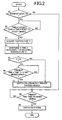
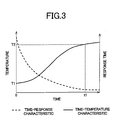
- FIG. 1 A liquid crystal display device according to an embodiment of the present invention will be described in detail below with reference to Figs. 1 to 3 where is presented a schematic block diagram showing an essential construction (Fig. 1), a flowchart depicting the on-timer operation (Fig. 2) and "time-temperature/response time" characteristics of a liquid crystal display device according to an embodiment of the present invention (Fig. 3).
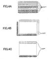
- Figs. 4A, 4B and 4C illustrate the locations of backlight sources using CCFT disposed direct under the LCD panel (direct-illuminating)(Fig. 4A) and side-illuminating CCFT (Figs. 4B and 4C) relative to the respective LCD panels.
- a liquid crystal display device in the shown embodiment comprises a tuner 1 for outputting an image signal of a designated channel of a television broadcast received from an antenna (not shown) and an electrode driving portion 2 for driving electrodes to apply a voltage to a LCD panel 3 according to the image signal of the channel selected by the tuner 1.
- the device is provided with a direct-illuminating or side-illuminating type backlight source 4 disposed behind the LCD panel 3 and a light source driving portion 5 for putting on and out the backlight source 4.
- the backlight source 4 may be of various kinds of light generators such as for example fluorescent lamps (CCFT) and light-emitting diodes (LED).
- the LCD device also has a remote control light receiving portion 6 for receiving input information signals (e.g., a viewing start time, end time, viewing channel) from a remote controller (not shown), a temperature sensor 7 for detecting an inside temperature of the device (ambient working temperature) and a microcomputer 8 for controlling the operation of the tuner 1, electrode driving portion 2, light source driving portion 5 and other not-shown circuits of the LCD device based on the various kinds of information received through the remote control light receiving portion 6 and the data detected by the temperature sensor 7.
- input information signals e.g., a viewing start time, end time, viewing channel
- a remote controller not shown
- a temperature sensor 7 for detecting an inside temperature of the device (ambient working temperature)
- a microcomputer 8 for controlling the operation of the tuner 1, electrode driving portion 2, light source driving portion 5 and other not-shown circuits of the LCD device based on the various kinds of information received through the remote control light receiving portion 6 and the data detected by the temperature sensor 7.
- the viewing start time, end time and channel number of a television broadcast program to be reserved for viewing can be easily preset by the user by utilizing an EPG (Electronic Program Guide) information multiplexed and transmitted as carried by the television broadcast signal.
- EPG Electronic Program Guide
- the temperature sensor 7 is desirably disposed to directly sense the temperature of the LCD panel 3. It is also possible to arrange a plurality of temperature sensors at different suitable positions in the LCD device.
- the microcomputer 8 examines whether the warm-up mode of the present invention has been preset or not at the time of on-timer reservation (Step S1). If the warm-up mode has been preset, the microcomputer 8 examines whether or not it is time tn earlier than the time preset for starting viewing (the viewing start time) (Step S2 ).
- the time tn is a preset time (for example 15 minutes or 30 minutes, etc.) which may be preset to a fixed time on the workshop before shipping the device or may be preset by the user to any desirable time when using on-timer reservation.
- the microcomputer 8 acquires the inside temperature T1 of the device detected at that moment by the temperature sensor 7 (Step S3) and determines a time t1 necessary for rising the temperature T1 of the LCD panel 3 by heat emitted from the turned-on backlight source 4 to a normal operating temperature T2 (e.g., 60°C) of the liquid crystal (Step S4).
- a normal operating temperature T2 e.g. 60°C
- the microcomputer 8 compares time t1 determined in Step S4 with time tn (Step S5) . If t1 is larger than tn, the backlight source 4 is immediately turned on (Step S7). If t1 is less than tn, the microcomputer 8 examines whether the present time is the time when t1 is subtracted from the viewing start time (Step S6). When it is just t1 earlier than the viewing start time, the microcomputer 8 turns on the backlight source 4 (Step S7).
- the backlight source 4 is driven to lighten and heat the LCD panel 3 before the viewing start time, the LCD panel 3 can reliably reach the normal operating temperature T2 at the viewing start time which is preset by user.
- T2 normal operating temperature
- the LCD panel 3 can reliably reach the normal operating temperature T2 at the viewing start time which is preset by user.
- nothing is displayed on the LCD panel screen (i.e., a black screen is presented) by applying a black signal voltage to the data electrodes of the LCD panel 3.
- Step S8 When the present time reached the viewing start time (Step S8), the microcomputer 8 switches on the system of the LCD device by supplying electric power to the tuner 1 and other circuits (Step S9). Therefore, an image signal of the viewing reserved channel selected by the tuner 1 is output to the electrode driving portion 2 to display the desired video image on the LCD panel 3.
- the liquid crystal display device can present to viewers a desired video of high image quality with no degradation due to the response characteristic of liquid crystal at low temperature on the LCD panel from the viewing start time. For example, when the user programmed (repeated reservation for every day or every week, etc.) viewing a television program starting early morning in winter season, he/she can enjoy a high-quality video of the reserved program from the beginning (the viewing start time) only by presetting the warm-up mode of the device.
- the warm-up mode is preset by the user.
- the LCD device may automatically do the warm-up mode operation in accordance with the ambient temperature without presetting by the user.
- Step S1 in Fig. 1 is not necessary and the processing may always start from Step S2. It is also possible to start the processing from Step S2 only in the case the device detected the desired program is to start for example in early morning (0:00 ⁇ 8:00 AM) of the winter season (from December to February) by using a calendar clock function in the microcomputer 8.
- the backlight source 4 which has a heat generating effect is used as the heating means for warming the LCD panel 3.
- the LCD panel 3 may be warmed up by heat emitted from any other circuit power supply or by using electrodes themselves of LCD panel 3 as heating elements. It is of course possible to heat the LCD panel 3 by use of a separate heating element such as a heater etc..
- the backlight source 4 by turning on the backlight source 4 in advance before the viewing start time like the above-described embodiment it is possible not only to assure a necessary response speed of liquid crystal at the viewing start time but also to stabilize the operation of CCFT composing the backlight source 4 at the viewing start time. It is known that the CCFT can emit light having high brightness when its wall temperature is of about 50 to 70°C. Accordingly, the warm-up operation by using the backlight source assures the user of viewing the video program on the sufficiently illuminated screen of the LCD panel from the beginning of viewing the program.
- the above-described embodiment determines a least necessary period t1 of the warm-up operation at the time tn earlier than the viewing start time for saving the power consumption of the warm-up operation of the backlight source 4 before the viewing start time.
- all of CCFT or LED composing the backlight source 4 are lit at the time tn earlier than the viewing start time to heat a whole surface of the liquid crystal panel.
- the warm-up operation of the LCD device before the viewing start time may be performed by turning on only CCFT disposed on the lower portion of the LCD panel as shown in Fig. 4A to 4C where CCFT to be driven for warming the LCD panel are hatched and the LCD panel is drawn by a broken line.
- Step S7 of the flowchart shown in Fig. 2 only a part of the backlight source is turned on in Step S7 of the flowchart shown in Fig. 2 and a whole backlight source is turned on at the time of switch on system in Step S9.
- This can effectively and uniformly rise the temperature of a whole surface of the LCD panel and save the power consumption during the warm-up operation of the device as compared with the case of all of the backlight source is turned on.
- the warm-up operation may be performed by step-by-step increasing the number of working CCFT or LED or the number of lines of working CCFT or LED of the backlight source.
- the lower CCFT/LED of the backlight source shall be turned on first to uniformly rise the temperature of the LCD panel.
- the device in the above-described embodiment applies a black signal voltage to data electrodes of the LCD panel 3 to present a black screen thereon during the warm-up operation till the viewing start time. It may also present on the screen a message or symbol of time till the beginning of viewing the program indicating that the device is now operating in the warm-up mode (Heating means is ON) by using OSD (On-Screen Display).
- OSD On-Screen Display
- the device may change a screen image for example from a black level pattern to a white level pattern and reverse at a constant time interval by alternately applying different particular pattern data voltages to the electrodes of the LCD panel 3 during the warm-up operation of the LCD panel 3.
- molecules of liquid crystal layer of the LCD panel are forced to move intensively, resulting in improvement of the response characteristic of the liquid crystal.
- the time of starting viewing a video program is input by the user and preset on the timer of the device. It is also possible to use information of EPG (Electronic Program Guide).
- EPG Electronic Program Guide
- the device stores a program viewing pattern (history) by using information of EPG, presumes a television program preferred by the user based on the stored program viewing pattern and automatically conducts the warm-up operation before the time of starting the program. This also enables the user to view an interesting television program with high quality of video images from its beginning without on-timer reservation by the user.
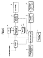
- FIG. 5 is a schematic block diagram showing the construction of an essential portion of the liquid crystal display device according to this embodiment.
- Figs. 6A and 6B are schematic illustrations of an example of an OS (overshoot) table memory for the liquid crystal device according to this embodiment.
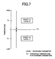
- Fig. 7 shows a relationship between an inside temperature of the LCD device and contents of reference table memory for the liquid crystal device according to the present embodiment.
- Fig. 8 is a graph showing a relationship between a voltage applied to the liquid crystal and a response of the liquid crystal of LCD device according to the present embodiment.
- the liquid crystal display device uses a method of driving the liquid crystal display panel by applying a driving (overshoot) voltage higher than a predetermined gradation level voltage or a driving (undershoot) voltage lower than the predetermined gradation level voltage for the input image signal (input video signal) of a present frame to the LCD panel according to a combination of an input image signal of a preceding frame with an input image signal of a present frame to improve the problem of the response speed of liquid crystal.
- a driving (overshoot) voltage higher than a predetermined gradation level voltage or a driving (undershoot) voltage lower than the predetermined gradation level voltage for the input image signal (input video signal) of a present frame to the LCD panel according to a combination of an input image signal of a preceding frame with an input image signal of a present frame to improve the problem of the response speed of liquid crystal.
- OS overshoot
- FIG. 5 there are shown two OS table memories (ROM) 11a and 11b storing applicable voltage data (enhancing parameters) according to gradation level transition before and after one frame period of an input image signal and corresponding inside temperatures of the device.
- Numeral 12 designates a frame memory (FM)
- numeral 13 designates an enhancing portion which compares an input image signal (current data) of a frame No. M to be displayed with an input image signal (previous data) of a frame No. M-1 stored in the frame memory 12, reads an enhancing parameter corresponding to the comparison result (gradation level transition) from the OS table memory (ROM) 11a or 11b and determines an enhanced signal (gradation level data to be written) necessary for displaying the frame No. M based on the enhancing parameter.
- ROM OS table memory
- a microcomputer 18 outputs a table selection control signal to the enhancing portion 13 for selecting one of the OS table memories (ROM) 11a and 11b and changing an enhancing parameter according to the inside temperature detected by the temperature sensor 7.
- Enhancing parameters LEVEL 1 and LEVEL 2 stored in the OS table memories 11a and 11b respectively are predetermined from the measurements of optical response characteristic of the LCD panel 3, which values were measured in the environment at different reference temperatures T3 and T4 (T3 ⁇ T4) respectively.
- the relationship of two enhancing rates are LEVEL 1 > LEVEL 2.
- the OS table memory may hold enhancing parameters (actually measured values) corresponding to 256 gradation levels.
- it may hold merely enhancing parameters (actually measured values) for 9 representative gradation levels at intervals of 32 gradation levels as shown in Figs. 6A and 6B.
- enhancement signals for other gradation levels may be separately calculated from the above actually measured values for example by linear interpolation. This can save the capacity of the OS table memories (ROM).
- the microcomputer 18 examines whether its inside temperature T1 detected by a temperature sensor 7 is lower than the threshold value Th as shown in Fig. 7, then, if so, causes the enhancing potion 13 to select the OS table memory (ROM) 11a and refer to the content thereof.
- the enhancing portion 13 does enhancement of the input image signal with use of enhancing parameters LEVEL 1 stored in the OS table memory (ROM) 11a.
- the microcomputer 18 instructs the enhancing potion 13 to select the OS table memory (ROM) 11b and refer to the content thereof.
- the enhancing portion 13 does enhancement of the input image signal with use of enhancing parameters LEVEL 2 stored in the OS table memory (ROM) 11b.
- the liquid crystal By doing the overshoot driving to compensate optical response characteristic of the LCD panel 3 in accordance with the working ambient temperature, it becomes possible for the liquid crystal to achieve a specified transmittance (target gradation level luminance) of an input image signal within the period of one frame (e.g., 16.7msec for progressive scanning at 60Hz) as shown in Fig. 8.
- a specified transmittance target gradation level luminance
- the target half tone of the image can be presented within a short period (1 frame period).
- the enhancing parameters LEVEL 1 and LEVEL 2 are applicable voltage data actually measured at the reference temperatures T3 and T4, respectively, at which the application of the voltage could cause the liquid crystals to respond to a transmittance decided by an input image signal after one frame period. If the inside temperature T1 differs largely from the reference temperature T3 or T4, the enhancement by using either of the OS table memories (ROMs) 11a and 11b could not bring the liquid crystals to precisely respond to the transmittance decided by the input image signal just after one frame period. Namely, the input image signal could not correctly be displayed.
- the OS table memories (ROMs) 11a and 11b could not bring the liquid crystals to precisely respond to the transmittance decided by the input image signal just after one frame period. Namely, the input image signal could not correctly be displayed.
- the liquid crystal display device in the present embodiment does warming the LCD panel 3 for a specified period before the viewing start time so that the LCD panel can reach within the period either the reference temperature T3 or T4 at which the enhancing parameters LEVEL 1 or LEVEL 2 could be measured in the environment.
- the LCD panel can present a high-quality video thereon from the beginning of viewing the video.
- the microcomputer 18 determines a period t3 necessary for warming the LCD panel 3 up to the reference temperature T3 by driving the backlight source 4 to lighten at the time t3 earlier than the viewing start time to heat the LCD panel 3.
- the microcomputer 18 determines a period t4 necessary for warming the LCD panel 3 up to the reference temperature T4 by driving the backlight source 4 to lighten at the time t4 earlier than the viewing start time to heat the LCD panel 3.
- the LCD panel 3 can be reliably warmed up to the reference temperature T3 or T4 by the viewing start time preset by user by driving the backlight source 4 to heat the liquid crystal display panel before the viewing start time.
- This makes it possible for the LCD panel 3 to reliably respond to a transmittance (target gradation level luminance) specified by an input image signal just after one vertical scanning period (one frame period) irrespective of the ambient temperature, thus presenting the high-quality video image from the beginning of viewing the video program.
- enhancing parameters LEVEL 1 and LEVEL 2 respectively corresponding to two temperature ranges, based on the detected inside temperature of the device and does the overshoot driving (enhancement) by using enhancing parameters LEVEL 1 or LEVEL 2, it may of course use any number M (M is 1 or more than 1) of enhancing parameters LEVEL 1 to LEVEL m which are selected to do adaptive overshoot driving (enhancement).
- the LCD panel 3 is warmed up to a temperature which is higher than the detected inside temperature T1 of the device and the lowest reference temperature Tm (1 ⁇ m ⁇ M). This can shorten the warm-up period before the viewing start time, saving the power consumption of the warm-up operation. This also enables the liquid crystal to respond a transmittance specified by an input image signal precisely after one frame period thereon from the beginning of viewing the video program, thus providing high-quality video with no afterimage.
- the above-described embodiment uses two OS table memories (ROM) 11a and 11b each storing enhancing parameters (applicable voltage data) arranged in a two-dimensional matrix, which parameters are addressable by an image signal of the current frame and an image signal of the previous frame and does enhancement of the current frame image signal by using designated enhancing parameters to compensate the optical response characteristic of the LCD panel to any input video image having any gradation level transition, thereby providing the correct display of the video on the LCD panel.
- enhancing parameters applicable voltage data
- a plurality of enhancing parameters corresponding to different temperature ranges are stored in separate OS table memories (ROM). It is also possible to use a single OS table memory (ROM) capable of storing different kinds of enhancing parameters for different temperature ranges in different table areas which are adaptively referenced to by a selection control signal from the microcomputer 18. By doing so, enhancing parameters are selectively used to provide an enhanced signal to the LCD panel 3.
- OS table memories ROM
- enhancing parameters are selectively used to provide an enhanced signal to the LCD panel 3.
- the enhancement of an input image signal to compensate the optical response characteristic of the LCD panel 3 may be also performed by using, for example, two-dimensional functions f (pre, cur) with variable representing gradation levels before and after transition which were prepared as enhancing parameters for each of temperatures of the device.
- the liquid crystal display devices according to the present invention are constructed as described above and can heat the LCD panel from a specified time earlier than a reserved viewing start time so that the LCD panel can reach a temperature at which the input image can correctly displayed thereon at the viewing start time.
- the LCD devices can present to the user a high-quality video on the LCD panel from the beginning of viewing.
Landscapes
- Physics & Mathematics (AREA)
- Engineering & Computer Science (AREA)
- General Physics & Mathematics (AREA)
- Nonlinear Science (AREA)
- Theoretical Computer Science (AREA)
- Crystallography & Structural Chemistry (AREA)
- Chemical & Material Sciences (AREA)
- Computer Hardware Design (AREA)
- Optics & Photonics (AREA)
- Mathematical Physics (AREA)
- Liquid Crystal (AREA)
- Liquid Crystal Display Device Control (AREA)
- Control Of Indicators Other Than Cathode Ray Tubes (AREA)
Abstract
Description
Claims (9)
- A liquid crystal display device for displaying a video on a liquid crystal display panel (3), characterized in that it is provided with a heating means for heating the liquid crystal display panel (3) for a specified period of time earlier than a time preset for starting viewing a video program.
- A liquid crystal display device as defined in claim 1, characterized in that the specified period of time is determined in accordance with a working ambient temperature.
- A liquid crystal display device as defined in claim 1, characterized in that the heating means is a backlight source (4) for illuminating the liquid crystal display panel (3).
- A liquid crystal display device as defined in claim 3, characterized in that merely a part of the backlight source (4) is used as the heating means.
- A liquid crystal display device as defined in claim 4, characterized in that the part of backlight source (4) used as the heating means corresponds to a lower portion of the liquid crystal display panel (3).
- A liquid crystal display device as defined in any one of claims 3 to 5, characterized in that an indicator indicating the heating means being driven for warming the liquid crystal display panel (3) is displayed as an OSD (On-Screen Display).
- A liquid crystal display device for displaying video on a liquid crystal display panel (3), characterized in that it is provided with a storage means for storing enhancing parameters for causing the liquid crystal display panel (3) to respond to a transmittance to be decided by an input video signal after a vertical scanning period, an enhancing means for enhancing the input video signal by using an enhancing parameter to compensate for optical response characteristic of the liquid crystal display panel (3) and a heating means for heating the liquid crystal display panel (3) for a specified period earlier than a time preset to start viewing on the liquid crystal display panel (3) to warm the liquid crystal display panel (3) to reach at the time preset to start viewing up to a reference temperature of an ambience in which the enhancing parameters were actually measured.
- A liquid crystal display device as defined in claim 7, characterized in that the storage means holds a plurality of enhancing parameters for enabling the liquid crystal display panel (3) to respond to transmittance to be decided by an input video signal after a vertical scanning period at a plurality of different reference temperatures and the heating means warms the liquid crystal display panel (3) up to a temperature equal to lowest one of the reference temperatures but higher than the working ambient temperature at the time preset to start viewing.
- A liquid crystal display device as defined in claim 7 or 8, characterized in that the storage means is a table memory storing therein enhancing parameters decided by a video signal of a current vertical scanning period and a video signal of a previous vertical scanning period.
Applications Claiming Priority (6)
| Application Number | Priority Date | Filing Date | Title |
|---|---|---|---|
| JP2002170790 | 2002-06-12 | ||
| JP2002170790 | 2002-06-12 | ||
| JP2002209342 | 2002-07-18 | ||
| JP2002209342 | 2002-07-18 | ||
| JP2003112498 | 2003-04-17 | ||
| JP2003112498A JP3602843B2 (en) | 2002-06-12 | 2003-04-17 | Liquid crystal display |
Publications (3)
| Publication Number | Publication Date |
|---|---|
| EP1372022A2 true EP1372022A2 (en) | 2003-12-17 |
| EP1372022A3 EP1372022A3 (en) | 2005-02-02 |
| EP1372022B1 EP1372022B1 (en) | 2008-09-03 |
Family
ID=29587476
Family Applications (1)
| Application Number | Title | Priority Date | Filing Date |
|---|---|---|---|
| EP03011914A Expired - Lifetime EP1372022B1 (en) | 2002-06-12 | 2003-05-27 | Liquid crystal display device |
Country Status (9)
| Country | Link |
|---|---|
| US (1) | US7145625B2 (en) |
| EP (1) | EP1372022B1 (en) |
| JP (1) | JP3602843B2 (en) |
| KR (1) | KR100604297B1 (en) |
| CN (1) | CN1469169B (en) |
| DE (1) | DE60323296D1 (en) |
| ES (1) | ES2314143T3 (en) |
| MY (1) | MY134357A (en) |
| TW (1) | TWI308969B (en) |
Cited By (3)
| Publication number | Priority date | Publication date | Assignee | Title |
|---|---|---|---|---|
| US7625092B2 (en) | 2005-08-09 | 2009-12-01 | Samsung Electronics Co., Ltd. | Video display apparatus and method for driving lamp in advance of watching |
| WO2011147500A1 (en) * | 2010-05-26 | 2011-12-01 | Johnson Controls Automotive Electronics Gmbh | Device and method for improving the response time of liquid crystal displays |
| EP3614043A1 (en) * | 2018-08-22 | 2020-02-26 | Stanley Electric Co., Ltd. | Control device for vehicular lamp, control method for vehicular lamp, vehicular lamp system |
Families Citing this family (28)
| Publication number | Priority date | Publication date | Assignee | Title |
|---|---|---|---|---|
| FR2919837B1 (en) * | 2007-08-10 | 2010-01-15 | Renault Sas | METHOD FOR CONTROLLING A MULTIMEDIA SYSTEM ON VEHICLE, DEVICE FOR IMPLEMENTING SAID METHOD |
| JP4239735B2 (en) * | 2003-07-14 | 2009-03-18 | 株式会社デンソー | In-vehicle display device |
| TWI234397B (en) * | 2003-12-05 | 2005-06-11 | Tatung Co Ltd | Method to preheat the display |
| CN100373861C (en) * | 2004-04-21 | 2008-03-05 | 华为技术有限公司 | Software upgrade device and method in communication network management system |
| TWI251200B (en) * | 2004-07-16 | 2006-03-11 | Au Optronics Corp | A liquid crystal display with an image flicker elimination function applied when power-on and an operation method of the same |
| CN100397187C (en) * | 2005-02-04 | 2008-06-25 | 友达光电股份有限公司 | Backlight module system and liquid crystal display using the same |
| US8970562B2 (en) * | 2005-03-01 | 2015-03-03 | Apple Inc. | LCD module with thermal sensor integrated and its implementation |
| WO2007037042A1 (en) * | 2005-09-27 | 2007-04-05 | Sharp Kabushiki Kaisha | Liquid crystal display device, instrument panel, automotive vehicle, and liquid crystal display method |
| US20070085807A1 (en) * | 2005-10-19 | 2007-04-19 | Rosemount Inc. | LCD design for cold temperature operation |
| JP2007148369A (en) * | 2005-10-31 | 2007-06-14 | Toshiba Matsushita Display Technology Co Ltd | Display control circuit, display control method, and display circuit |
| KR101228923B1 (en) * | 2006-03-02 | 2013-02-01 | 엘지이노텍 주식회사 | Apparatus for Uniformalizing Luminance of LCD |
| JP2008102490A (en) * | 2006-09-19 | 2008-05-01 | Funai Electric Co Ltd | Liquid crystal display device and liquid crystal television |
| JP5139666B2 (en) * | 2006-11-06 | 2013-02-06 | Necディスプレイソリューションズ株式会社 | Brightness adjusting device and brightness adjusting method |
| JP5081495B2 (en) * | 2007-05-02 | 2012-11-28 | 三洋電機株式会社 | Image display device |
| TWI372276B (en) | 2007-06-20 | 2012-09-11 | Au Optronics Corp | Liquid crystal display and method for making the same |
| EP2020655A1 (en) * | 2007-07-25 | 2009-02-04 | Funai Electric Co., Ltd. | Liquid crystal display device and liquid crystal television |
| CN101933400A (en) * | 2008-02-01 | 2010-12-29 | 松下电器产业株式会社 | Liquid crystal display device and backlight device |
| JP5310136B2 (en) * | 2009-03-13 | 2013-10-09 | ソニー株式会社 | Liquid crystal display device and method for controlling power supply of liquid crystal display device |
| CN101866637B (en) * | 2010-06-13 | 2012-02-01 | 青岛海信电器股份有限公司 | Power-on time sequence control method for liquid crystal display equipment and television |
| KR101323443B1 (en) * | 2010-06-16 | 2013-10-29 | 엘지디스플레이 주식회사 | Liquid crystal display device |
| JP6213211B2 (en) * | 2013-12-18 | 2017-10-18 | セイコーエプソン株式会社 | Projector and projector control method |
| JP2015127756A (en) * | 2013-12-27 | 2015-07-09 | 本田技研工業株式会社 | Liquid crystal display |
| KR20160056197A (en) * | 2014-11-11 | 2016-05-19 | 삼성전자주식회사 | Method for controlling display and electronic device thereof |
| CN108073018A (en) * | 2016-11-15 | 2018-05-25 | 深圳市光峰光电技术有限公司 | The startup method of optic modulating device and dependent projections equipment |
| CN107092117B (en) * | 2017-06-29 | 2019-11-12 | 京东方科技集团股份有限公司 | Display panel and method for improving display quality of display panel |
| US10935830B1 (en) * | 2017-11-14 | 2021-03-02 | Facebook Technologies, Llc | Apparatuses, systems, and methods for heating a liquid crystal display screen |
| CN111624837B (en) | 2019-02-27 | 2022-06-14 | 中强光电股份有限公司 | Projector with a light source |
| CN118968936B (en) * | 2024-07-25 | 2025-06-17 | 优创光电科技(盐城)有限公司 | A method and system for adjusting the image of a liquid crystal display screen |
Family Cites Families (22)
| Publication number | Priority date | Publication date | Assignee | Title |
|---|---|---|---|---|
| JPS526111B1 (en) * | 1971-07-14 | 1977-02-18 | ||
| US4279012A (en) * | 1978-10-23 | 1981-07-14 | Massachusetts Microcomputers, Inc. | Programmable appliance controller |
| US4773735A (en) * | 1986-08-04 | 1988-09-27 | Allied-Signal Inc. | Fast warm-up heater for liquid crystal display |
| JPS63161432A (en) | 1986-12-24 | 1988-07-05 | Tokyo Electric Co Ltd | Temperature control method for thermal writing LCD panel |
| US4901147A (en) * | 1987-03-30 | 1990-02-13 | Kabushiki Kaisha Toshiba | Video system with self-diagnose function |
| JPS6459330A (en) | 1987-08-31 | 1989-03-07 | Toshiba Corp | Back light device for on-vehicle liquid crystal television |
| JPH01140520U (en) | 1988-03-22 | 1989-09-26 | ||
| JP2655434B2 (en) | 1989-06-29 | 1997-09-17 | 日本電気株式会社 | Matrix liquid crystal display |
| JPH0398085A (en) | 1989-09-11 | 1991-04-23 | Victor Co Of Japan Ltd | After-image canceling circuit of liquid crystal display device |
| US5088806A (en) * | 1990-01-16 | 1992-02-18 | Honeywell, Inc. | Apparatus and method for temperature compensation of liquid crystal matrix displays |
| US5164849A (en) * | 1990-10-05 | 1992-11-17 | Allied-Signal Inc. | Liquid crystal display with a fast warm up |
| JP2849677B2 (en) | 1990-11-29 | 1999-01-20 | 本田技研工業株式会社 | Display device for vehicles |
| JPH052164A (en) * | 1991-01-28 | 1993-01-08 | Toshiba Corp | Lcd module |
| JP3052418B2 (en) | 1991-04-17 | 2000-06-12 | カシオ計算機株式会社 | LCD panel drive |
| JPH04365094A (en) | 1991-06-12 | 1992-12-17 | Casio Comput Co Ltd | Liquid crystal panel driving device |
| EP0843838A1 (en) * | 1995-07-31 | 1998-05-27 | Litton Systems Canada Limited | Heater system for a flat panel such as a liquid crystal display |
| KR100241286B1 (en) * | 1996-09-23 | 2000-02-01 | 구본준 | A liquid crystal display device |
| JPH10228013A (en) | 1997-02-13 | 1998-08-25 | Rohm Co Ltd | Liquid crystal display element |
| JP3514946B2 (en) * | 1997-05-29 | 2004-04-05 | 日産自動車株式会社 | Liquid crystal display |
| JPH11345445A (en) | 1998-05-29 | 1999-12-14 | Fujitsu Ten Ltd | Audio visual system |
| JP2000036143A (en) | 1998-07-17 | 2000-02-02 | Hitachi Ltd | Recording and playback device |
| US6898762B2 (en) * | 1998-08-21 | 2005-05-24 | United Video Properties, Inc. | Client-server electronic program guide |
-
2003
- 2003-04-17 JP JP2003112498A patent/JP3602843B2/en not_active Expired - Fee Related
- 2003-05-26 TW TW092114180A patent/TWI308969B/en not_active IP Right Cessation
- 2003-05-27 ES ES03011914T patent/ES2314143T3/en not_active Expired - Lifetime
- 2003-05-27 EP EP03011914A patent/EP1372022B1/en not_active Expired - Lifetime
- 2003-05-27 DE DE60323296T patent/DE60323296D1/en not_active Expired - Lifetime
- 2003-06-02 US US10/449,518 patent/US7145625B2/en not_active Expired - Fee Related
- 2003-06-09 MY MYPI20032137A patent/MY134357A/en unknown
- 2003-06-12 KR KR1020030037782A patent/KR100604297B1/en not_active Expired - Fee Related
- 2003-06-12 CN CN031486452A patent/CN1469169B/en not_active Expired - Fee Related
Cited By (5)
| Publication number | Priority date | Publication date | Assignee | Title |
|---|---|---|---|---|
| US7625092B2 (en) | 2005-08-09 | 2009-12-01 | Samsung Electronics Co., Ltd. | Video display apparatus and method for driving lamp in advance of watching |
| WO2011147500A1 (en) * | 2010-05-26 | 2011-12-01 | Johnson Controls Automotive Electronics Gmbh | Device and method for improving the response time of liquid crystal displays |
| US9164317B2 (en) | 2010-05-26 | 2015-10-20 | Marc Rawer | Device and method for improving the response time of liquid crystal displays |
| EP3614043A1 (en) * | 2018-08-22 | 2020-02-26 | Stanley Electric Co., Ltd. | Control device for vehicular lamp, control method for vehicular lamp, vehicular lamp system |
| US11009734B2 (en) | 2018-08-22 | 2021-05-18 | Stanley Electric Co., Ltd. | Control device for vehicular lamp, control method for vehicular lamp, vehicular lamp system |
Also Published As
| Publication number | Publication date |
|---|---|
| KR100604297B1 (en) | 2006-07-28 |
| TWI308969B (en) | 2009-04-21 |
| ES2314143T3 (en) | 2009-03-16 |
| CN1469169A (en) | 2004-01-21 |
| KR20030096042A (en) | 2003-12-24 |
| EP1372022B1 (en) | 2008-09-03 |
| MY134357A (en) | 2007-12-31 |
| CN1469169B (en) | 2011-04-20 |
| US7145625B2 (en) | 2006-12-05 |
| US20030231157A1 (en) | 2003-12-18 |
| TW200405074A (en) | 2004-04-01 |
| DE60323296D1 (en) | 2008-10-16 |
| EP1372022A3 (en) | 2005-02-02 |
| JP2004102222A (en) | 2004-04-02 |
| JP3602843B2 (en) | 2004-12-15 |
Similar Documents
| Publication | Publication Date | Title |
|---|---|---|
| US7145625B2 (en) | Liquid crystal display device having heater | |
| CN102549649B (en) | Liquid crystal display device | |
| TWI404021B (en) | Liquid crystal display and display control method for the same | |
| US8451209B2 (en) | Liquid crystal display device | |
| JP4011104B2 (en) | Liquid crystal display | |
| JP2001125067A (en) | Liquid crystal display | |
| US20230274710A1 (en) | Method for compensating driving parameters for a display and circuit system for the same | |
| KR101433106B1 (en) | Liquid crystal display and driving method thereof | |
| WO2010024053A1 (en) | Image display device, television receiver, driving method for the image display device, and driving method for the television receiver | |
| JPH08201812A (en) | Liquid crystal display device | |
| WO2010137362A1 (en) | Display apparatus, and television reception apparatus | |
| CN101006392B (en) | Projector device | |
| JPH11283759A (en) | Liquid crystal display device | |
| KR101482077B1 (en) | A light source driving method, a backlight assembly for performing the same, and a display device having the same | |
| JP3617996B2 (en) | Liquid crystal display | |
| JP3875918B2 (en) | Liquid crystal display device and driving method thereof | |
| US20110242144A1 (en) | Display apparatus for displaying image | |
| JP2006330222A (en) | Liquid crystal display device and method for correcting deterioration over time | |
| JP3569184B2 (en) | Liquid crystal display | |
| JP2000132138A (en) | Transmissive display | |
| KR101512521B1 (en) | Method for controlling lamp luminance in a display device | |
| JP2013228561A (en) | Display control device, display device, and display control method | |
| KR20080030172A (en) | Backlight Control Device and Method | |
| JP2013125157A (en) | Video display device | |
| HK1172726A (en) | Liquid crystal display device |
Legal Events
| Date | Code | Title | Description |
|---|---|---|---|
| PUAI | Public reference made under article 153(3) epc to a published international application that has entered the european phase |
Free format text: ORIGINAL CODE: 0009012 |
|
| AK | Designated contracting states |
Kind code of ref document: A2 Designated state(s): AT BE BG CH CY CZ DE DK EE ES FI FR GB GR HU IE IT LI LU MC NL PT RO SE SI SK TR |
|
| AX | Request for extension of the european patent |
Extension state: AL LT LV MK |
|
| PUAL | Search report despatched |
Free format text: ORIGINAL CODE: 0009013 |
|
| AK | Designated contracting states |
Kind code of ref document: A3 Designated state(s): AT BE BG CH CY CZ DE DK EE ES FI FR GB GR HU IE IT LI LU MC NL PT RO SE SI SK TR |
|
| AX | Request for extension of the european patent |
Extension state: AL LT LV MK |
|
| 17P | Request for examination filed |
Effective date: 20050318 |
|
| 17Q | First examination report despatched |
Effective date: 20050414 |
|
| AKX | Designation fees paid |
Designated state(s): DE ES FR GB |
|
| GRAP | Despatch of communication of intention to grant a patent |
Free format text: ORIGINAL CODE: EPIDOSNIGR1 |
|
| GRAS | Grant fee paid |
Free format text: ORIGINAL CODE: EPIDOSNIGR3 |
|
| GRAA | (expected) grant |
Free format text: ORIGINAL CODE: 0009210 |
|
| AK | Designated contracting states |
Kind code of ref document: B1 Designated state(s): DE ES FR GB |
|
| REG | Reference to a national code |
Ref country code: GB Ref legal event code: FG4D |
|
| REF | Corresponds to: |
Ref document number: 60323296 Country of ref document: DE Date of ref document: 20081016 Kind code of ref document: P |
|
| REG | Reference to a national code |
Ref country code: ES Ref legal event code: FG2A Ref document number: 2314143 Country of ref document: ES Kind code of ref document: T3 |
|
| PLBE | No opposition filed within time limit |
Free format text: ORIGINAL CODE: 0009261 |
|
| STAA | Information on the status of an ep patent application or granted ep patent |
Free format text: STATUS: NO OPPOSITION FILED WITHIN TIME LIMIT |
|
| 26N | No opposition filed |
Effective date: 20090604 |
|
| REG | Reference to a national code |
Ref country code: FR Ref legal event code: PLFP Year of fee payment: 13 |
|
| PGFP | Annual fee paid to national office [announced via postgrant information from national office to epo] |
Ref country code: ES Payment date: 20150527 Year of fee payment: 13 Ref country code: DE Payment date: 20150521 Year of fee payment: 13 Ref country code: GB Payment date: 20150521 Year of fee payment: 13 |
|
| PGFP | Annual fee paid to national office [announced via postgrant information from national office to epo] |
Ref country code: FR Payment date: 20150521 Year of fee payment: 13 |
|
| REG | Reference to a national code |
Ref country code: DE Ref legal event code: R119 Ref document number: 60323296 Country of ref document: DE |
|
| GBPC | Gb: european patent ceased through non-payment of renewal fee |
Effective date: 20160527 |
|
| REG | Reference to a national code |
Ref country code: FR Ref legal event code: ST Effective date: 20170131 |
|
| PG25 | Lapsed in a contracting state [announced via postgrant information from national office to epo] |
Ref country code: DE Free format text: LAPSE BECAUSE OF NON-PAYMENT OF DUE FEES Effective date: 20161201 Ref country code: FR Free format text: LAPSE BECAUSE OF NON-PAYMENT OF DUE FEES Effective date: 20160531 |
|
| PG25 | Lapsed in a contracting state [announced via postgrant information from national office to epo] |
Ref country code: GB Free format text: LAPSE BECAUSE OF NON-PAYMENT OF DUE FEES Effective date: 20160527 |
|
| PG25 | Lapsed in a contracting state [announced via postgrant information from national office to epo] |
Ref country code: ES Free format text: LAPSE BECAUSE OF NON-PAYMENT OF DUE FEES Effective date: 20160528 |
|
| REG | Reference to a national code |
Ref country code: ES Ref legal event code: FD2A Effective date: 20181203 |