EP1371975A1 - Electrophoretic apparatus with protection for its detectors - Google Patents
Electrophoretic apparatus with protection for its detectors Download PDFInfo
- Publication number
- EP1371975A1 EP1371975A1 EP02077324A EP02077324A EP1371975A1 EP 1371975 A1 EP1371975 A1 EP 1371975A1 EP 02077324 A EP02077324 A EP 02077324A EP 02077324 A EP02077324 A EP 02077324A EP 1371975 A1 EP1371975 A1 EP 1371975A1
- Authority
- EP
- European Patent Office
- Prior art keywords
- separation
- channel
- detection
- electrodes
- voltage source
- Prior art date
- Legal status (The legal status is an assumption and is not a legal conclusion. Google has not performed a legal analysis and makes no representation as to the accuracy of the status listed.)
- Withdrawn
Links
- 238000001514 detection method Methods 0.000 claims abstract description 85
- 238000000926 separation method Methods 0.000 claims abstract description 80
- 239000007788 liquid Substances 0.000 claims description 16
- 230000003321 amplification Effects 0.000 claims description 3
- 238000003199 nucleic acid amplification method Methods 0.000 claims description 3
- 238000000034 method Methods 0.000 description 11
- 230000005684 electric field Effects 0.000 description 10
- 239000000470 constituent Substances 0.000 description 8
- 238000005370 electroosmosis Methods 0.000 description 6
- 239000012530 fluid Substances 0.000 description 4
- 230000002269 spontaneous effect Effects 0.000 description 3
- 238000005251 capillar electrophoresis Methods 0.000 description 2
- 239000011248 coating agent Substances 0.000 description 2
- 238000000576 coating method Methods 0.000 description 2
- 238000003487 electrochemical reaction Methods 0.000 description 2
- 238000002474 experimental method Methods 0.000 description 2
- 238000002955 isolation Methods 0.000 description 2
- HBMJWWWQQXIZIP-UHFFFAOYSA-N silicon carbide Chemical compound [Si+]#[C-] HBMJWWWQQXIZIP-UHFFFAOYSA-N 0.000 description 2
- 230000001360 synchronised effect Effects 0.000 description 2
- 238000012935 Averaging Methods 0.000 description 1
- 230000015572 biosynthetic process Effects 0.000 description 1
- 239000003990 capacitor Substances 0.000 description 1
- 230000003247 decreasing effect Effects 0.000 description 1
- 238000001962 electrophoresis Methods 0.000 description 1
- 238000005755 formation reaction Methods 0.000 description 1
- 238000010348 incorporation Methods 0.000 description 1
- 238000005259 measurement Methods 0.000 description 1
- 238000012544 monitoring process Methods 0.000 description 1
- 230000007935 neutral effect Effects 0.000 description 1
- 102000039446 nucleic acids Human genes 0.000 description 1
- 108020004707 nucleic acids Proteins 0.000 description 1
- 150000007523 nucleic acids Chemical class 0.000 description 1
- 230000003071 parasitic effect Effects 0.000 description 1
- 238000012545 processing Methods 0.000 description 1
- 102000004169 proteins and genes Human genes 0.000 description 1
- 108090000623 proteins and genes Proteins 0.000 description 1
Images


Classifications
-
- G—PHYSICS
- G01—MEASURING; TESTING
- G01N—INVESTIGATING OR ANALYSING MATERIALS BY DETERMINING THEIR CHEMICAL OR PHYSICAL PROPERTIES
- G01N27/00—Investigating or analysing materials by the use of electric, electrochemical, or magnetic means
- G01N27/26—Investigating or analysing materials by the use of electric, electrochemical, or magnetic means by investigating electrochemical variables; by using electrolysis or electrophoresis
- G01N27/416—Systems
- G01N27/447—Systems using electrophoresis
- G01N27/44704—Details; Accessories
- G01N27/44717—Arrangements for investigating the separated zones, e.g. localising zones
- G01N27/4473—Arrangements for investigating the separated zones, e.g. localising zones by electric means
Definitions
- the present invention relates to an electrophoretic system, comprising a separation system and a detection system, said separation system comprising a channel and a first separation electrode located at a first end of the channel and a second separation electrode located at a second end of the channel, said separation system being arranged in such a way that a potential difference can be applied between the first and second separation electrodes, said detection system, in use, being positioned close to channel or inside the channel.
- Electrophoretic techniques are commonly used to identify constituents in a sample, for example proteins or nucleic acids.
- the method is based on the fact that different molecules travel at different speeds through a medium, under influence of an electrical field applied to that medium.
- the difference in the velocities is caused by the different features of the different molecules, such as different masses, sizes, shapes, charges etc.
- Capillary electrophoresis is a technique using electrophoresis in a channel, for instance a tube, filled with a conductive fluid. On one end of the channel a sample is located. When an electrical field is applied to the channel, preferably in the longitudinal direction of the channel, the constituents of the sample will travel through the channel. Such an electrical field can be established by, for instance, applying a positive electrode to the end of the channel where the sample is originally located and connecting the other end of the channel to ground.
- Such an electrical field will also generate an electroosmotic flow.
- This electroosmotic flow is the movement of the liquid with respect to the electrical field. This flow is for instance directed to the exit of the channel at a low potential, e.g., ground.
- the electrophoretic movement of the sample molecules through the liquid is different for different molecules.
- a detection apparatus placed, for instance, at the end of the channel, or halfway, can successively detect the different constituents of which the sample is formed.
- the positive molecules will reach the detection apparatus.
- These molecules are repelled by the positive electrode and are dragged along in the electroosmotic flow.
- the neutral elements will reach the detection apparatus.
- Those elements are not influenced by the electrical field, but are dragged along with the electroosmotic flow.
- the negative elements will reach the detection apparatus.
- a problem that occurs with such electrophoretic systems is that as a result of the electrical field applied to the channel filled with the conductive liquid, the potential in the channel varies linearly through the channel and will only be near zero at the end of the grounded channel.
- the detection apparatus is located somewhere along the channel, preferably in the vicinity of the channel, or even in contact with the walls of the channel or even partly inside the channel.
- this detection apparatus doesn't necessarily have the same potential as the channel at the location of the detection apparatus and is preferably grounded.
- the detection and the separation systems do not have the same potential.
- a DC-current can arise between the channel and the detection apparatus or there is a risk of electrical breakthrough between the channel and the detection apparatus, causing undesired disturbances or damaging the system.
- US Patent 5.322.607 from Hewlett-Packard Company discloses an electrical potential configuration for a capillary electrophoretic system, in which the risk for such spontaneous discharges is minimised. This is done by providing the channel with a resistive layer (conductive coating) on its outside and applying two extra electrodes to this coating. The two extra electrodes adjust the potential of that resistive layer in such a way that the potential equals the potential of the detection apparatus at the position of the detection apparatus.
- this system has the disadvantage that complicated adjustments need to be made to the separation system. Such a compensation technique is not easily incorporated in existing systems.
- the object of the present invention is to provide an electrophoretic system in which any current between the separation system and the detection system, and the risk of electrical breakthrough at the detection system is further reduced.
- the invention provides a system as defined in the outset, characterised in that the electrophoretic system comprises means to reduce a voltage difference between the separation system and the detection system in order to prevent electrical breakthrough between the separation system and the detection system, where said means to reduce said voltage difference comprise a DC-voltage source.
- This DC-voltage source is an easy to use device, that is also readily available.
- Such a system can establish a ground potential at the detection system in a well defined way.
- the separation voltage supply is grounded, simplifies the incorporation of the system with existing systems and reduces interface problems with the high voltage supply that would otherwise occur.
- the electrophoretic system can further comprise at least one potential sensor provided close to the detection system, which controls the DC-voltage source. This makes it possible to monitor the potential in the channel and control the DC-voltage source.
- the detection system can further comprise one or more electrodes and a first AC-voltage source where a conductivity of a liquid is determined by measuring parameters obtained from the electrodes. This allows for an electrical detection system.
- the detection system can further comprise one or more electrodes that are in galvanic contact with the liquid. This makes it possible to use electrodes that do not have an insulating layer.
- the electrophoretic system can further comprise a second AC-voltage source connected to the second separation electrode.
- This second AC-voltage can, for instance, be controlled by the first AC-voltage source, for instance via an amplifier.
- Such a second AC-voltage source will prevent leak-currents to flow from the detection system to the separation system.
- Fig. 1 shows an electrophoretic system according to the present invention, comprising a channel 1, for instance a tube, and two separation electrodes 2 and 3, where the first separation electrode 2 is positioned to a first end of the channel 1 and where the second separation electrode 3 is positioned to a second end of the channel 1.
- the channel 1 is preferably filled with a conductive liquid.
- a separation voltage V sep is maintained between the first and second separation electrodes 2 and 3 by a DC-source 4.
- the second separation electrode 3 is connected to ground via an extra DC-voltage source 21.
- the DC-source 4 will establish a potential difference between the first and second separation electrode 2, 3. This set-up will result in a substantially linear electrical field along the inside of the channel 1.
- the potential difference between the separation electrodes 2, 3 is preferably in the range from 1 kV to 50 kV.
- a detection system comprising four detection electrodes 11, 12, 13, 14, of which the first detection electrode 11 is connected to an AC-voltage source 7. Close to these detection electrodes 11, 12, 13, 14, a sensor 20 is positioned, for instance, a sensing electrode.
- the detection system will detect the passage of the constituents by measuring the conductivity of the conductive liquid in between these detection electrodes 11, 12, 13, 14.
- the passage of the constituents will influence the conductivity of the conductive liquid.
- the circuitry used to measure this conductivity is shown in figure 2.
- FIG. 2 shows a more detailed view of this detection system.
- V in is preferably kept below 100 mV amplitude in order to avoid electrochemical reactions at the electrodes 11, 12, 13, 14.
- the resulting current I o between the two outer detection electrodes 11, 12 is measured with, for instance, a transimpedance amplifier 15 and applied to a computer system 17 via, for instance, a multimeter 19, e.g., a keithley 177.
- a transimpedance amplifier 15 is measured with, for instance, a transimpedance amplifier 15 and applied to a computer system 17 via, for instance, a multimeter 19, e.g., a keithley 177.
- the resulting current I o can be measured and applied to computer system 17 in many different ways, as is known to a person skilled in the art.
- the resulting differential voltage V o between the inner detection electrodes 13, 14 is measured using a high impedance differential-amplifier 18, for instance lock in amplifier 16, e.g., a Perkin-Elmer 7265.
- the measured voltage is applied to the computer system 17.
- the differential voltage V o can be measured and applied to the computer system 17 in many different ways, as is known to a person skilled in the art.
- the signals I o and V o are preferably converted into a digital format, in order to allow further processing by the computer system 17.
- the computer system 17 can compute and display the liquid conductivity from the ratio I o /V o . From this ratio information can be retrieved about the constituents 6 passing the detection system as a function of time.
- the transimpedance amplifier 15 and the high impedance amplifier 18 are mounted together with the micromechanical measurement system on a printed circuit board.
- the connections between the electronics and the detection electrodes are kept as short as possible in order to reduce parasitic capacitance's.
- the separation voltage V sep is applied to the first and second separation electrodes 2 and 3.
- the total voltage difference inside the channel will be smaller than the applied V sep due to the presence of contact potentials at the separation electrodes 2 and 3. This is shown in figure 3a. So, when V sep is mentioned, one should realise that the actual voltage difference inside the channel is smaller than V sep .
- the system of figure 1 will suffer from the potential difference between the detection system with respect to the local potential of the channel 1 and the walls of the channel 1 due to the separation voltage V sep applied to the first and second separation electrode 2, and 3 by DC-source 4.
- the detection electrodes 11, 12, 13, 14 are protected with an insulating layer (not shown) made of, e.g., silicon carbide (SiC) which is, e.g., only 30 nm thick.
- SiC silicon carbide
- the extra DC-voltage source 21 is added in between the second separation electrode 3 and the ground.
- the voltage of this extra DC-voltage source 21 is such, that the potential in the detection system at the location of the detection electrodes 11, 12, 13, 14 is reduced to such a value that no electrical breakthrough occurs between the detection system fluid and any one of the electrodes 11, 12, 13, 14.
- this value is substantially zero.
- the DC-voltage source 21 may be controlled manually. However, in order to control the extra DC-voltage source 21, a sensor 20 is provided. This sensor 20 is located close to the four detection electrodes 11, 12, 13, 14, for instance, in a plane parallel to the first and second separation electrodes 2, 3, for instance 15 ⁇ m away from the detection electrodes 11, 12, 13, 14. Of course, the sensor 20 can be positioned at any suitable distance from the detection electrodes 11, 12, 13, 14. The sensor 20 is connected to the extra DC-voltage source 21, via a control system 10. Of course, the sensor 20 can be all kinds of sensors known to a person skilled in the art. It is also possible to use a plurality of sensors 20, where the end value is determined, based on the values measured by the different sensors 20. This can for instance be done by averaging the values measured by the plurality of sensors 20.
- the senor 20 has a galvanic contact with the conductive liquid and therefore can measure the DC-potential.
- the sensor controls the extra DC-voltage source 21 in such a way that the extra DC-voltage source 21 provides the second separation electrode 3 with a compensation voltage.
- This control has only been indicated very schematically in figure 1.
- V comp compensation voltage
- the compensation technique described above makes it also possible to use detection electrodes 11, 12, 13, 14, that are in galvanic contact with the conductive liquid. This is only possible when the potential difference between the detection system and the separation system is very small. So, the dimensions of the detection electrodes 11, 12, 13, 14 need to be relatively small and the amplitude of V in should also be relatively small, as will readily be understood by a person skilled in the art.
- the exact potential of the second separation electrode 3 is not exactly known.
- sensor 20 is omitted, and extra DC-voltage source 21 is not controlled using the actual measured potential at the location of the detection system, but an estimated value of the potential at the location of the detection system is applied to the extra DC-voltage source 21.
- the error in the potential of the second separation electrode 3 due to the compensation will in general be small compared to the error in the potential of the second separation electrode 3 due to the DC-source 4.
- the extra error, due to the compensation can be accounted for using an extra feedback system, known to a person skilled in the art.
- the set-up discussed above makes it possible to use a detection system, which is in contact with, or located close to the channel 1, without the risks discussed above.
- the potential of the second separation electrode 3 is compensated, but compensation can also be applied to the first separation electrode 2 or both the first and second separation electrode 2, 3.
- the compensation system described can be used in all sorts of electrophoretic systems, using all sorts of detection methods and/or systems, known to a person skilled in the art.
- the compensation technique can be used for all kinds of detection systems placed inside or outside the channel 1, in contact with the walls of the channel 1 or not in contact with the walls of the channel 1.
- Figure 3b shows experimental results obtained with the set-up according to the set-up shown in figure 1 (dashed lines).
- Frequency responses of the detection apparatus measured with the apparatus shown in figure 2 are depicted in the frequency range from 100 Hz- 100 kHz, using solutions of 2 and 20 mM Mes/HIS(pH 6) for the separation fluid.
- the separation voltage V sep was approximately 600 Volts and the compensation voltage V comp applied to the second separation electrode 3 with voltage source 21 was approximately -1 Volt.
- Figure 3b shows the measured impedance as a function of the frequency of V in applied to the detection electrodes 11, 12, 13, 14.
- the curve for the 2mM solution is higher than for the 20 mM solution.
- the ratio between the measured impedances is not a constant as a function of the frequency, and below approximately 1 kHz, the response is reversed. The reason for this will be discussed below.
- the four detection electrodes 11, 12, 13, 14 are preferably located close to the second separation electrode 3, because the separation of the constituents of sample 5 is better further away from the first separation electrode 2. However, due to the introduced potential difference between the first detection electrode 11 and the second separation electrode 3, an AC-leak-current can develop between the first detection electrode 11, which is connected to the AC-voltage source 7 and the second separation electrode 3.
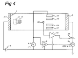
- Figure 4 shows a further embodiment, in which the problem of AC-leak-currents has been reduced, by applying an AC-voltage produced by further AC-voltage source 7 to the second separation electrode 3 and synchronised with AC-voltage V in and, in this example, an amplitude of 0,5 x V in .
- This can be implemented by the set-up of figure 4 where the further AC-voltage source 9 is located between the second separation electrode 3 and voltage source 21 and synchronised with AC-voltage V in by means of an output signal received from an amplifier 8 connected to the voltage source 7.
- Same reference numbers are used to denote the same parts as in figure 1.
- Further AC-voltage 9 reduces the AC-potential difference between the first detection electrode 11 and the second separation electrode 3, preventing an AC-leak-current to flow between the first detection electrode 11 and the second separation electrode 3.
- Further AC-voltage source 9 can be controlled in such a way that the potential difference between the detection system and the separation system at the location of the detection system for AC is decreased. This can be done, for instance, by using a feedback system (not shown), as is known to a person skilled in the art.
- the amplifier 8 has an amplification factor of 0,5 , so effectively functions as an attenuator. However, depending on the exact purposes and circumstances, other amplification factors can be used. Amplifier 8 can be all sorts of amplifiers known to a person skilled in the art.
- Figure 3b shows the results obtained for the same experiments as discussed above (full lines), but now performed with the set-up according to figure 4.
- the top and bottom line correspond, respectively, to the 2 and 20 mM concentration.
- the ratio between the two responses is substantially constant over the usable frequency range.
Landscapes
- Health & Medical Sciences (AREA)
- Life Sciences & Earth Sciences (AREA)
- Molecular Biology (AREA)
- Chemical & Material Sciences (AREA)
- Chemical Kinetics & Catalysis (AREA)
- Electrochemistry (AREA)
- Physics & Mathematics (AREA)
- Analytical Chemistry (AREA)
- Biochemistry (AREA)
- General Health & Medical Sciences (AREA)
- General Physics & Mathematics (AREA)
- Immunology (AREA)
- Pathology (AREA)
- Investigating Or Analyzing Materials By The Use Of Electric Means (AREA)
- Electrochromic Elements, Electrophoresis, Or Variable Reflection Or Absorption Elements (AREA)
Abstract
Electrophoretic system having a separation system and a detection system,
where the separation system has a channel (1) and a first separation electrode (2)
located at a first end of the channel (1) and a second separation electrode (3) located at
the second end of the channel (1), where the separation system is arranged in such a
way that a potential difference can be applied between the first and second separation
electrode (2, 3), where the detection system, in use, is positioned close to the channel
(1) or inside the channel (1), the system having means to reduce a voltage difference
between the separation system and the detection system in order to prevent electrical
breakthrough between the separation system and the detection system.
Description
- The present invention relates to an electrophoretic system, comprising a separation system and a detection system, said separation system comprising a channel and a first separation electrode located at a first end of the channel and a second separation electrode located at a second end of the channel, said separation system being arranged in such a way that a potential difference can be applied between the first and second separation electrodes, said detection system, in use, being positioned close to channel or inside the channel.
- Electrophoretic techniques are commonly used to identify constituents in a sample, for example proteins or nucleic acids. The method is based on the fact that different molecules travel at different speeds through a medium, under influence of an electrical field applied to that medium. The difference in the velocities is caused by the different features of the different molecules, such as different masses, sizes, shapes, charges etc.
- Capillary electrophoresis is a technique using electrophoresis in a channel, for instance a tube, filled with a conductive fluid. On one end of the channel a sample is located. When an electrical field is applied to the channel, preferably in the longitudinal direction of the channel, the constituents of the sample will travel through the channel. Such an electrical field can be established by, for instance, applying a positive electrode to the end of the channel where the sample is originally located and connecting the other end of the channel to ground.
- Such an electrical field will also generate an electroosmotic flow. This electroosmotic flow is the movement of the liquid with respect to the electrical field. This flow is for instance directed to the exit of the channel at a low potential, e.g., ground.
- The electrophoretic movement of the sample molecules through the liquid, in the example described above, is different for different molecules. A detection apparatus placed, for instance, at the end of the channel, or halfway, can successively detect the different constituents of which the sample is formed. First the positive molecules will reach the detection apparatus. These molecules are repelled by the positive electrode and are dragged along in the electroosmotic flow. Then the neutral elements will reach the detection apparatus. Those elements are not influenced by the electrical field, but are dragged along with the electroosmotic flow. Finally, the negative elements will reach the detection apparatus. Although the positive electrode attracts these elements, they are dragged along with the electroosmotic flow.
- A problem that occurs with such electrophoretic systems is that as a result of the electrical field applied to the channel filled with the conductive liquid, the potential in the channel varies linearly through the channel and will only be near zero at the end of the grounded channel. The detection apparatus is located somewhere along the channel, preferably in the vicinity of the channel, or even in contact with the walls of the channel or even partly inside the channel. However, this detection apparatus doesn't necessarily have the same potential as the channel at the location of the detection apparatus and is preferably grounded. The detection and the separation systems do not have the same potential. As a result of this, a DC-current can arise between the channel and the detection apparatus or there is a risk of electrical breakthrough between the channel and the detection apparatus, causing undesired disturbances or damaging the system.
- Known solutions to avoid such undesired DC-currents and/or spontaneous discharges are based on the isolation of the separation system and the detection system. This can for instance be done by using known isolation techniques or using an off-column detection apparatus, where the detection apparatus has no contact with the separation channel. However, these adjustments are not straightforward and require additional equipment.
- US Patent 5.322.607 from Hewlett-Packard Company discloses an electrical potential configuration for a capillary electrophoretic system, in which the risk for such spontaneous discharges is minimised. This is done by providing the channel with a resistive layer (conductive coating) on its outside and applying two extra electrodes to this coating. The two extra electrodes adjust the potential of that resistive layer in such a way that the potential equals the potential of the detection apparatus at the position of the detection apparatus. However, this system has the disadvantage that complicated adjustments need to be made to the separation system. Such a compensation technique is not easily incorporated in existing systems.
- Other known solutions attempt to solve the problem by isolating the separation system from the detection system, using for instance extra modules in order to pass on the detection signal to further process units without a DC-potential.
- Another known solution is described in Electronic protection methods for conductivity detectors in micro capillary electrophoresis devices, by J. Bastemeijer et al, Sensors and Actuators B 83 (2002) 98 - 103, Elsevier. This document discloses a protection technique that uses a floating high voltage supply to generate an electrical field to the channel. The floating high voltage is biased in such a way that the DC level in the channel at the location of the detector should remain at about ground potential. As a result of that, the object is that no potential difference is present between the channel and the detection apparatus, so the risk of electrical breakthrough is minimised. However, this system has the disadvantage that such floating high voltage supplies are not easy available. Also, it is difficult to establish a well-defined ground level at the location of the detector by using a floating high voltage supply and, therefore, the risk of electrical breakthrough remains.
- The object of the present invention is to provide an electrophoretic system in which any current between the separation system and the detection system, and the risk of electrical breakthrough at the detection system is further reduced.
- In order to obtain this object, the invention provides a system as defined in the outset, characterised in that the electrophoretic system comprises means to reduce a voltage difference between the separation system and the detection system in order to prevent electrical breakthrough between the separation system and the detection system, where said means to reduce said voltage difference comprise a DC-voltage source. This DC-voltage source is an easy to use device, that is also readily available. Such a system can establish a ground potential at the detection system in a well defined way. Moreover, because of the fact that the need for a floating high voltage supply is omitted, the system will be a much safer system to use and the systems integrity is ensured. Also, the fact that the separation voltage supply is grounded, simplifies the incorporation of the system with existing systems and reduces interface problems with the high voltage supply that would otherwise occur.
- The electrophoretic system can further comprise at least one potential sensor provided close to the detection system, which controls the DC-voltage source. This makes it possible to monitor the potential in the channel and control the DC-voltage source.
- The detection system can further comprise one or more electrodes and a first AC-voltage source where a conductivity of a liquid is determined by measuring parameters obtained from the electrodes. This allows for an electrical detection system.
- The detection system can further comprise one or more electrodes that are in galvanic contact with the liquid. This makes it possible to use electrodes that do not have an insulating layer.
- The electrophoretic system can further comprise a second AC-voltage source connected to the second separation electrode. This second AC-voltage can, for instance, be controlled by the first AC-voltage source, for instance via an amplifier. Such a second AC-voltage source will prevent leak-currents to flow from the detection system to the separation system.
- The invention will be explained with reference to some drawings which are only intended to illustrate the present invention and not to limit its scope which is only limited by the appended claims.
- Figure 1 shows an electrophoretic system according to a first embodiment of the present invention.
- Figure 2 shows a preferred embodiment of the detection system according to the present invention.
- Figure 3a shows a graph of the separation voltage through the electrophoretic system.
- Figure 3b shows experimental results obtained using the set-up of figure 1 respectively figure 4.
- Figure 4 shows an electrophoretic system according to a further aspect of the present invention.
-
- For the purpose of teaching the invention, preferred embodiments of the method and devices of the invention are described in the sequel. It will be apparent for the person skilled in the art that other alternative and equivalent embodiments of the invention can be conceived and reduced to practice without departing from the true spirit of the invention, the scope of the invention being only limited by the annexed claims.
- Fig. 1 shows an electrophoretic system according to the present invention, comprising a
channel 1, for instance a tube, and twoseparation electrodes first separation electrode 2 is positioned to a first end of thechannel 1 and where thesecond separation electrode 3 is positioned to a second end of thechannel 1. Thechannel 1 is preferably filled with a conductive liquid. A separation voltage Vsep is maintained between the first andsecond separation electrodes source 4. Thesecond separation electrode 3 is connected to ground via an extra DC-voltage source 21. The DC-source 4 will establish a potential difference between the first andsecond separation electrode channel 1. The potential difference between theseparation electrodes - Inside the
channel 1, a detection system is positioned, comprising fourdetection electrodes first detection electrode 11 is connected to an AC-voltage source 7. Close to thesedetection electrodes sensor 20 is positioned, for instance, a sensing electrode. - When a
sample 5 is placed in the channel, preferably close to thefirst separation electrode 2, theconstituents 6 of thatsample 5 will start to travel through thechannel 1, due to the electrophoretic movement and the electroosmotic flow, both generated by the electrical field provided by theseparation electrodes - The detection system will detect the passage of the constituents by measuring the conductivity of the conductive liquid in between these
detection electrodes - Figure 2 shows a more detailed view of this detection system. Vin is preferably kept below 100 mV amplitude in order to avoid electrochemical reactions at the
electrodes - The resulting current Io between the two
outer detection electrodes transimpedance amplifier 15 and applied to acomputer system 17 via, for instance, amultimeter 19, e.g., a keithley 177. Of course, the resulting current Io can be measured and applied tocomputer system 17 in many different ways, as is known to a person skilled in the art. - The resulting differential voltage Vo between the
inner detection electrodes amplifier 18, for instance lock inamplifier 16, e.g., a Perkin-Elmer 7265. The measured voltage is applied to thecomputer system 17. Of course, the differential voltage Vo can be measured and applied to thecomputer system 17 in many different ways, as is known to a person skilled in the art. - The signals Io and Vo are preferably converted into a digital format, in order to allow further processing by the
computer system 17. Thecomputer system 17 can compute and display the liquid conductivity from the ratio Io/Vo. From this ratio information can be retrieved about theconstituents 6 passing the detection system as a function of time. - In a preferred embodiment, the
transimpedance amplifier 15 and thehigh impedance amplifier 18 are mounted together with the micromechanical measurement system on a printed circuit board. Preferably, the connections between the electronics and the detection electrodes are kept as short as possible in order to reduce parasitic capacitance's. - Of course, also other detection systems can be used. It is, for instance, possible to measure the conductivity of the liquid using two, three, or any other suitable amount of detection electrodes.
- The separation voltage Vsep is applied to the first and
second separation electrodes separation electrodes - However, the system of figure 1, as described so far, will suffer from the potential difference between the detection system with respect to the local potential of the
channel 1 and the walls of thechannel 1 due to the separation voltage Vsep applied to the first andsecond separation electrode source 4. Thedetection electrodes channel 1. - In order to minimise the potential difference between the detection system and the local potential of the separation system due to the separation voltage Vsep, the extra DC-
voltage source 21 is added in between thesecond separation electrode 3 and the ground. The voltage of this extra DC-voltage source 21 is such, that the potential in the detection system at the location of thedetection electrodes electrodes - The DC-
voltage source 21 may be controlled manually. However, in order to control the extra DC-voltage source 21, asensor 20 is provided. Thissensor 20 is located close to the fourdetection electrodes second separation electrodes instance 15 µm away from thedetection electrodes sensor 20 can be positioned at any suitable distance from thedetection electrodes sensor 20 is connected to the extra DC-voltage source 21, via acontrol system 10. Of course, thesensor 20 can be all kinds of sensors known to a person skilled in the art. It is also possible to use a plurality ofsensors 20, where the end value is determined, based on the values measured by thedifferent sensors 20. This can for instance be done by averaging the values measured by the plurality ofsensors 20. - In a preferred embodiment, the
sensor 20 has a galvanic contact with the conductive liquid and therefore can measure the DC-potential. The sensor controls the extra DC-voltage source 21 in such a way that the extra DC-voltage source 21 provides thesecond separation electrode 3 with a compensation voltage. This control has only been indicated very schematically in figure 1. There are several ways to implement such an electronically controlled adjustment of the voltage output ofvoltage source 21, as is known to persons skilled in the art. There is no restriction in the implementation of the electronically controlled voltage source embodiment. For instance, whensensor 20 measures a local voltage Vmeas the extra DC-voltage source 21 provides thesecond separation electrode 3 with a compensation voltage Vcomp that is almost equal to minus Vmeas. The DC-voltage of the separation system fluid at the location of the detection system will become close to zero. - The compensation technique described above, makes it also possible to use
detection electrodes detection electrodes - As a result of the constant monitoring and compensation of the potential at the
second separation electrode 3, the exact potential of thesecond separation electrode 3 is not exactly known. For this reason, in another embodiment,sensor 20 is omitted, and extra DC-voltage source 21 is not controlled using the actual measured potential at the location of the detection system, but an estimated value of the potential at the location of the detection system is applied to the extra DC-voltage source 21. - However, the error in the potential of the
second separation electrode 3 due to the compensation will in general be small compared to the error in the potential of thesecond separation electrode 3 due to the DC-source 4. The extra error, due to the compensation, can be accounted for using an extra feedback system, known to a person skilled in the art. - The set-up discussed above makes it possible to use a detection system, which is in contact with, or located close to the
channel 1, without the risks discussed above. In the example discussed, the potential of thesecond separation electrode 3 is compensated, but compensation can also be applied to thefirst separation electrode 2 or both the first andsecond separation electrode - Of course, the compensation system described can be used in all sorts of electrophoretic systems, using all sorts of detection methods and/or systems, known to a person skilled in the art. The compensation technique can be used for all kinds of detection systems placed inside or outside the
channel 1, in contact with the walls of thechannel 1 or not in contact with the walls of thechannel 1. - Figure 3b shows experimental results obtained with the set-up according to the set-up shown in figure 1 (dashed lines). Frequency responses of the detection apparatus measured with the apparatus shown in figure 2 are depicted in the frequency range from 100 Hz- 100 kHz, using solutions of 2 and 20 mM Mes/HIS(pH 6) for the separation fluid. The separation voltage Vsep was approximately 600 Volts and the compensation voltage Vcomp applied to the
second separation electrode 3 withvoltage source 21 was approximately -1 Volt. - Figure 3b shows the measured impedance as a function of the frequency of Vin applied to the
detection electrodes - For frequencies substantially higher than 1 kHz, the curve for the 2mM solution is higher than for the 20 mM solution. However, as is clearly visible, the ratio between the measured impedances is not a constant as a function of the frequency, and below approximately 1 kHz, the response is reversed. The reason for this will be discussed below.
- The four
detection electrodes second separation electrode 3, because the separation of the constituents ofsample 5 is better further away from thefirst separation electrode 2. However, due to the introduced potential difference between thefirst detection electrode 11 and thesecond separation electrode 3, an AC-leak-current can develop between thefirst detection electrode 11, which is connected to the AC-voltage source 7 and thesecond separation electrode 3. - This leak-current particularly occurs at low frequencies. At low frequencies, the impedance of the
detection electrodes - Figure 4 shows a further embodiment, in which the problem of AC-leak-currents has been reduced, by applying an AC-voltage produced by further AC-
voltage source 7 to thesecond separation electrode 3 and synchronised with AC-voltage Vinand, in this example, an amplitude of 0,5 x Vin. This can be implemented by the set-up of figure 4 where the further AC-voltage source 9 is located between thesecond separation electrode 3 andvoltage source 21 and synchronised with AC-voltage Vin by means of an output signal received from anamplifier 8 connected to thevoltage source 7. Same reference numbers are used to denote the same parts as in figure 1. Further AC-voltage 9 reduces the AC-potential difference between thefirst detection electrode 11 and thesecond separation electrode 3, preventing an AC-leak-current to flow between thefirst detection electrode 11 and thesecond separation electrode 3. Further AC-voltage source 9 can be controlled in such a way that the potential difference between the detection system and the separation system at the location of the detection system for AC is decreased. This can be done, for instance, by using a feedback system (not shown), as is known to a person skilled in the art. - In the embodiment shown, the
amplifier 8 has an amplification factor of 0,5 , so effectively functions as an attenuator. However, depending on the exact purposes and circumstances, other amplification factors can be used.Amplifier 8 can be all sorts of amplifiers known to a person skilled in the art. - Figure 3b shows the results obtained for the same experiments as discussed above (full lines), but now performed with the set-up according to figure 4. The top and bottom line correspond, respectively, to the 2 and 20 mM concentration. The ratio between the two responses is substantially constant over the usable frequency range.
Claims (9)
- Electrophoretic system comprising a separation system and a detection system, said separation system comprising a channel (1) and a first separation electrode (2) located at a first end of the channel (1) and a second separation electrode (3) located at a second end of the channel (1),
said separation system being arranged in such a way that a potential difference can be applied between the first and second separation electrodes (2, 3),
said detection system, in use, being positioned close to channel (1) or inside the channel (1)
characterised in that
the electrophorctic system comprises means to reduce a voltage difference between the separation system and the detection system in order to prevent electrical breakthrough between the separation system and the detection system, where said means to reduce said voltage difference comprise a DC-voltage source (21). - Electrophoretic system according to claim 1, characterised in that at least one potential sensor (20) is provided located close to the detection system, which controls the DC-voltage source (21).
- Electrophoretic system according to any of the preceding claims,
characterised in that the detection system comprises one or more electrodes (11, 12, 13, 14) and a first AC-voltage source (7) and a conductivity of a liquid is determined by measuring parameters obtained from the electrodes (11, 12, 13, 14). - Electrophoretic system according to any of the preceding claims, characterised in that the detection system comprises four electrodes (11, 12, 13, 14) having two outer electrodes (11, 12) and a first AC-voltage source (7) connected to the two outer detection electrodes (11, 12) and a conductivity of a liquid in said channel (1) is determined by measuring parameters obtained from the electrodes (11, 12, 13, 14).
- Electrophoretic system according to claim 3 or 4, characterised in that the one or more electrodes (11, 12, 13, 14) are in galvanic contact with the liquid.
- Electrophoretic system according to claim 3, 4 or 5, characterised in that a second AC-voltage source (9) is connected to the second separation electrode 3.
- Electrophoretic system according to claim 6, characterised in that the second AC-voltage source (9) is controlled by the first AC-voltage source (7).
- Electrophoretic system according to claim 7, characterised in that said first AC-voltage source (7) is connected to said second AC-voltage source (9) via an amplifier (8).
- Electrophoretic system according to claim 8, characterised in that said amplifier (8) has an amplification factor equal to or smaller than 1.
Priority Applications (6)
| Application Number | Priority Date | Filing Date | Title |
|---|---|---|---|
| EP02077324A EP1371975A1 (en) | 2002-06-13 | 2002-06-13 | Electrophoretic apparatus with protection for its detectors |
| PCT/NL2003/000431 WO2003106991A1 (en) | 2002-06-13 | 2003-06-13 | Electrophoretic system with protection for its detectors |
| US10/517,524 US20060144710A1 (en) | 2002-06-13 | 2003-06-13 | Electrophoretic system with protection for its detectors |
| AU2003276550A AU2003276550A1 (en) | 2002-06-13 | 2003-06-13 | Electrophoretic system with protection for its detectors |
| CA002489302A CA2489302A1 (en) | 2002-06-13 | 2003-06-13 | Electrophoretic system with protection for its detectors |
| EP03741638A EP1527336A1 (en) | 2002-06-13 | 2003-06-13 | Electrophoretic system with protection for its detectors |
Applications Claiming Priority (1)
| Application Number | Priority Date | Filing Date | Title |
|---|---|---|---|
| EP02077324A EP1371975A1 (en) | 2002-06-13 | 2002-06-13 | Electrophoretic apparatus with protection for its detectors |
Publications (1)
| Publication Number | Publication Date |
|---|---|
| EP1371975A1 true EP1371975A1 (en) | 2003-12-17 |
Family
ID=29558393
Family Applications (2)
| Application Number | Title | Priority Date | Filing Date |
|---|---|---|---|
| EP02077324A Withdrawn EP1371975A1 (en) | 2002-06-13 | 2002-06-13 | Electrophoretic apparatus with protection for its detectors |
| EP03741638A Withdrawn EP1527336A1 (en) | 2002-06-13 | 2003-06-13 | Electrophoretic system with protection for its detectors |
Family Applications After (1)
| Application Number | Title | Priority Date | Filing Date |
|---|---|---|---|
| EP03741638A Withdrawn EP1527336A1 (en) | 2002-06-13 | 2003-06-13 | Electrophoretic system with protection for its detectors |
Country Status (5)
| Country | Link |
|---|---|
| US (1) | US20060144710A1 (en) |
| EP (2) | EP1371975A1 (en) |
| AU (1) | AU2003276550A1 (en) |
| CA (1) | CA2489302A1 (en) |
| WO (1) | WO2003106991A1 (en) |
Families Citing this family (2)
| Publication number | Priority date | Publication date | Assignee | Title |
|---|---|---|---|---|
| WO2011106098A2 (en) | 2010-02-25 | 2011-09-01 | Advanced Microlabs, Llc | Microfluidic interface for a microchip |
| US8603323B2 (en) * | 2010-09-20 | 2013-12-10 | Lifescan, Inc. | Apparatus and process for improved measurements of a monitoring device |
Citations (3)
| Publication number | Priority date | Publication date | Assignee | Title |
|---|---|---|---|---|
| GB1196887A (en) * | 1968-03-27 | 1970-07-01 | Rauno Erkki Virtanen | A Method of and Means for Establishing and for Making Quantitative Determinations of Zones Occuring in Electrophoresis. |
| EP0475713A1 (en) * | 1990-09-10 | 1992-03-18 | The Board Of Trustees Of The Leland Stanford Junior University | End-column electrical and electrochemical detector for capillary zone electrophoresis |
| US5322607A (en) * | 1992-07-14 | 1994-06-21 | Hewlett-Packard Company | Electrical potential configuration for an electrophoresis system |
Family Cites Families (1)
| Publication number | Priority date | Publication date | Assignee | Title |
|---|---|---|---|---|
| US7125478B2 (en) * | 2002-01-18 | 2006-10-24 | The Regents Of The University Of Michigan | Microscale electrophoresis devices for biomolecule separation and detection |
-
2002
- 2002-06-13 EP EP02077324A patent/EP1371975A1/en not_active Withdrawn
-
2003
- 2003-06-13 AU AU2003276550A patent/AU2003276550A1/en not_active Abandoned
- 2003-06-13 CA CA002489302A patent/CA2489302A1/en not_active Abandoned
- 2003-06-13 EP EP03741638A patent/EP1527336A1/en not_active Withdrawn
- 2003-06-13 WO PCT/NL2003/000431 patent/WO2003106991A1/en not_active Ceased
- 2003-06-13 US US10/517,524 patent/US20060144710A1/en not_active Abandoned
Patent Citations (3)
| Publication number | Priority date | Publication date | Assignee | Title |
|---|---|---|---|---|
| GB1196887A (en) * | 1968-03-27 | 1970-07-01 | Rauno Erkki Virtanen | A Method of and Means for Establishing and for Making Quantitative Determinations of Zones Occuring in Electrophoresis. |
| EP0475713A1 (en) * | 1990-09-10 | 1992-03-18 | The Board Of Trustees Of The Leland Stanford Junior University | End-column electrical and electrochemical detector for capillary zone electrophoresis |
| US5322607A (en) * | 1992-07-14 | 1994-06-21 | Hewlett-Packard Company | Electrical potential configuration for an electrophoresis system |
Non-Patent Citations (2)
| Title |
|---|
| BASTEMEIJER J ET AL: "Electronic protection methods for conductivity detectors in micro capillary electrophoresis devices", SENSORS AND ACTUATORS B, ELSEVIER SEQUOIA S.A., LAUSANNE, CH, vol. 83, no. 1-3, 15 March 2002 (2002-03-15), pages 98 - 103, XP004344491, ISSN: 0925-4005 * |
| PARK S ET AL: "VOLTAMMETRIC DETECTION FOR CAPILLARY ELECTROPHORESIS", ANALYTICAL CHEMISTRY, AMERICAN CHEMICAL SOCIETY. COLUMBUS, US, vol. 69, no. 15, 1 August 1997 (1997-08-01), pages 2994 - 3001, XP000699463, ISSN: 0003-2700 * |
Also Published As
| Publication number | Publication date |
|---|---|
| WO2003106991A8 (en) | 2005-04-07 |
| US20060144710A1 (en) | 2006-07-06 |
| AU2003276550A8 (en) | 2003-12-31 |
| CA2489302A1 (en) | 2003-12-24 |
| EP1527336A1 (en) | 2005-05-04 |
| AU2003276550A1 (en) | 2003-12-31 |
| WO2003106991A1 (en) | 2003-12-24 |
Similar Documents
| Publication | Publication Date | Title |
|---|---|---|
| US7084643B2 (en) | Capacitive sensor for non-contacting gap and dielectric medium measurement | |
| EP0716731B1 (en) | Magnetic flowmeter with empty pipe detector | |
| US6356097B1 (en) | Capacitive probe for in situ measurement of wafer DC bias voltage | |
| JP5128581B2 (en) | Magnetic particle measuring device and method | |
| US6345537B1 (en) | Devices for determining the flow characteristics of a multi-phase fluid | |
| EP2283325B1 (en) | Electromagnetic flowmeter and method with full pipe detection by the help of a third electrode | |
| EP2986965B1 (en) | A method of electrically measuring the electrical properties of individual particles flowing in a liquid | |
| US6749735B1 (en) | Electromobility focusing controlled channel electrophoresis system | |
| EP1223631A3 (en) | Arrangement and method for determining the electroconductivity of a coolant in a fuel cell stack by differential voltage measurements | |
| US20060144710A1 (en) | Electrophoretic system with protection for its detectors | |
| EP0559140B1 (en) | Corpuscle-detecting apparatus | |
| US4789829A (en) | Method and apparatus for determining RE gasket shielding effectiveness | |
| US6707306B1 (en) | Measuring method for a capacitive measuring system | |
| JP2001183194A (en) | Measuring apparatus for flow rate of measuring medium | |
| CN104204858B (en) | Condenser type location equipment | |
| KR101175384B1 (en) | Circuit pattern inspection device, method thereof and computer readable recording medium storing program therein | |
| KR102447910B1 (en) | Capillary Electrophoresis Cathode System and Method | |
| JP4404946B2 (en) | Method for measuring the flow rate of a medium | |
| WO2000075650A1 (en) | Potential gradient detector for electrophoresis | |
| EP2393963B1 (en) | Electromagnetic flowmeter having corrosion protection of measuring electrodes, and method incorporating the same | |
| US20260092857A1 (en) | Microparticle measuring apparatus | |
| Laugere et al. | Dedicated interface electronics for capacitively-coupled conductivity detection in on-chip capillary electrophoresis | |
| US20100148789A1 (en) | System for Measuring the Electric Potential of a Voltage Source | |
| WO2018229509A1 (en) | Sensing apparatus and sensing method | |
| JPH0219900B2 (en) |
Legal Events
| Date | Code | Title | Description |
|---|---|---|---|
| PUAI | Public reference made under article 153(3) epc to a published international application that has entered the european phase |
Free format text: ORIGINAL CODE: 0009012 |
|
| AK | Designated contracting states |
Kind code of ref document: A1 Designated state(s): AT BE CH CY DE DK ES FI FR GB GR IE IT LI LU MC NL PT SE TR |
|
| AX | Request for extension of the european patent |
Extension state: AL LT LV MK RO SI |
|
| AKX | Designation fees paid | ||
| REG | Reference to a national code |
Ref country code: DE Ref legal event code: 8566 |
|
| STAA | Information on the status of an ep patent application or granted ep patent |
Free format text: STATUS: THE APPLICATION IS DEEMED TO BE WITHDRAWN |
|
| 18D | Application deemed to be withdrawn |
Effective date: 20040618 |