EP1371959A2 - Electronic clinical thermometer - Google Patents
Electronic clinical thermometer Download PDFInfo
- Publication number
- EP1371959A2 EP1371959A2 EP03009535A EP03009535A EP1371959A2 EP 1371959 A2 EP1371959 A2 EP 1371959A2 EP 03009535 A EP03009535 A EP 03009535A EP 03009535 A EP03009535 A EP 03009535A EP 1371959 A2 EP1371959 A2 EP 1371959A2
- Authority
- EP
- European Patent Office
- Prior art keywords
- buzzer
- electronic thermometer
- securing member
- main body
- support structure
- Prior art date
- Legal status (The legal status is an assumption and is not a legal conclusion. Google has not performed a legal analysis and makes no representation as to the accuracy of the status listed.)
- Granted
Links
- 230000010355 oscillation Effects 0.000 abstract description 11
- 230000036760 body temperature Effects 0.000 abstract description 3
- 238000005516 engineering process Methods 0.000 description 5
- 238000005259 measurement Methods 0.000 description 5
- 238000000034 method Methods 0.000 description 4
- 230000002093 peripheral effect Effects 0.000 description 4
- 238000006243 chemical reaction Methods 0.000 description 3
- 230000000694 effects Effects 0.000 description 3
- IYZWUWBAFUBNCH-UHFFFAOYSA-N 2,6-dichlorobiphenyl Chemical compound ClC1=CC=CC(Cl)=C1C1=CC=CC=C1 IYZWUWBAFUBNCH-UHFFFAOYSA-N 0.000 description 2
- 238000004519 manufacturing process Methods 0.000 description 2
- 238000000926 separation method Methods 0.000 description 2
- 239000000853 adhesive Substances 0.000 description 1
- 230000001070 adhesive effect Effects 0.000 description 1
- 230000002411 adverse Effects 0.000 description 1
- 238000005452 bending Methods 0.000 description 1
- 230000005540 biological transmission Effects 0.000 description 1
- 239000000470 constituent Substances 0.000 description 1
- 238000010276 construction Methods 0.000 description 1
- 238000007373 indentation Methods 0.000 description 1
- 238000012986 modification Methods 0.000 description 1
- 230000004048 modification Effects 0.000 description 1
- XLYOFNOQVPJJNP-UHFFFAOYSA-N water Substances O XLYOFNOQVPJJNP-UHFFFAOYSA-N 0.000 description 1
- 238000004078 waterproofing Methods 0.000 description 1
Images


Classifications
-
- G—PHYSICS
- G01—MEASURING; TESTING
- G01K—MEASURING TEMPERATURE; MEASURING QUANTITY OF HEAT; THERMALLY-SENSITIVE ELEMENTS NOT OTHERWISE PROVIDED FOR
- G01K13/00—Thermometers specially adapted for specific purposes
- G01K13/20—Clinical contact thermometers for use with humans or animals
Definitions
- This invention relates to an electronic thermometer for measuring body temperature, and more particularly to such a thermometer capable of outputting a warning sound with improved quality.
- a clinical thermometer Since a clinical thermometer is inserted in the armpit or under the tongue to measure the body temperature, it is difficult to visually ascertain its current condition such as whether the measurement is still being taken or the measurement has been completed. For this reason, it has been known to incorporate a buzzer or the like in a clinical thermometer for acoustically outputting the condition of an electronic thermometer. In order to improve the dependability of the output, the sound wave pressure must be increased either by using a larger buzzer or applying an increased voltage to the buzzer.
- Japanese Patent Publication Tokko 4-30512 disclosed a circular buzzer contacting a rib inside the main housing of a thermometer so as to use the interior of the housing as a resonance chamber
- Japanese Patent Publication Tokko 4-77257 disclosed a buzzer placed in an indentation prepared by making a portion of the housing structure thinner for providing a resonance space similarly as described above and making the characteristic frequency of this thinned portion of the housing equal to that of the buzzer
- Japanese Patent Publication Tokkai 61-62831 and Japanese Patent 2539224 disclosed a structure having sound-conducting routes and openings connecting the inner space and the exterior of the main housing.
- Aforementioned Japanese Patent 2539224 also discloses an example whereby a resonance chamber is provided inside a buzzer unit which is separate from a box-like structure but since it is a separate unit from the module frame on which a printed circuit board (PCB) is affixed, the number of constituent parts to be assembled and hence also the number of steps in the production process are increased. Moreover, lead lines longer than the distance of separation will be required to connect the buzzer with the PCB. This will give rise to the problem of requiring a larger housing structure to contain these long lead lines as well as the problem of increased probability of breakage in the lead lines as they are bent.
- PCB printed circuit board
- the inner cavity and the resonance chamber come to directly communicate to the exterior and the thermometer cannot be completely waterproofed. If one must take into consideration the possibility of the internal resonance chamber becoming invaded with water, the buzzer and the resonance chamber may have to be connected in an airtight manner in order to protect the electrical circuits. For this purpose, the entire peripheral edge of the buzzer will have to be adhesively attached to the resonance chamber, and this will allow the oscillating plate of the buzzer to vibrate only under this fixed boundary condition. As a result, only the center point becomes the point of maximum amplitude in the primary mode of oscillation, and this brings about the problem of low efficiency in the conversion to sound energy.
- An electronic thermometer embodying this invention may be characterized as comprising not only a main body including a temperature detecting part and means for detecting and displaying temperature of the temperature detecting part, as do prior art thermometers, but also a buzzer that is elongated in a longitudinal direction, having a pair of mutually opposite end parts in the longitudinal direction and a support structure contained inside the main body such that the end parts of the buzzer are securely supported by this support structure.
- a buzzer that is elongated in a longitudinal direction, having a pair of mutually opposite end parts in the longitudinal direction and a support structure contained inside the main body such that the end parts of the buzzer are securely supported by this support structure.
- the support structure may be formed so as to have a support member for contacting the end parts of the buzzer from below. It is also preferable to form the support structure so as to contain therein a control circuit inclusive of a driving circuit for the buzzer. In this manner, the buzzer can be connected to its driving circuit with relatively shorter lead lines and the problems of making the thermometer bulky as a whole and causing the connecting lead lines to be damaged by bending them within a small space can be eliminated.
- the support structure may be provided with a sound chamber, or a resonance chamber. Its bottom surface, opposite to the buzzer, may be provided with a sound-conducting opening. In this manner, the structure of the main body becomes simpler than if a resonance space were to be provided inside the housing structure according to the prior art technology.
- the electronic thermometer may further comprise a buzzer-securing member for securing the buzzer, having contact parts that contact the buzzer only at its end parts from above, that is, in a direction opposite from the support member of the support structure.
- a buzzer-securing member for securing the buzzer, having contact parts that contact the buzzer only at its end parts from above, that is, in a direction opposite from the support member of the support structure.
- Fig. 1 shows an electronic thermometer 1 embodying this invention, comprising a main body 2 which is elongated and has a front tip forming a temperature detecting part 3, a battery cover 4 which is detachably attached to the back end part of the main body 2, a display device (LCD) 5 for displaying the result of measurement, a push button 6 provided on the back surface of the main body 2 for starting the operation of the thermometer, and an inner unit 7 disposed inside the main body 2.
- LCD display device
- the inner unit 7 is formed with a sub-case 8 having attached thereon a buzzer 9, a control circuit (with a PCB 10), a buzzer cover 11, the display device 5, a battery 12, lead lines and terminals (not shown) for connecting these components electrically, and a thermocouple (not shown) serving as the aforementioned temperature detecting part 3.
- the control circuit carries out an initialization process.
- the thermometer 1 is ready to take a measurement, an output to this effect is made through the display device 5 and the buzzer 9.
- the control circuit starts a temperature-measuring process and calculates a temperature value from the temperature detected by the temperature detecting part 3.
- the end of the process is communicated by the buzzer 9, and the calculated temperature value is displayed on the display device 5.
- the buzzer 9 is formed mainly with a piezoelectric plate 90 and an oscillating plate 91, the piezoelectric plate 90 being set above the oscillating plate 91.
- the piezoelectric plate 90 is circular in shape, but the oscillating plate 91 is of a shape which may be described as a circle (with diameter L) from which mutually opposite arch-shaped portions 91a are removed (or as a rectangle with a pair of mutually opposite edges of length W replaced by outwardly protruding arcs 91b of diameter L). This is to be compared with a traditional buzzer 9' with a circular piezoelectric plate 90' and a circular oscillating plate 91', as shown in Fig. 3B.
- the space for containing the buzzer 9 inside the sub-case 8 is limited, as shown at 80 in Fig. 5. If its width is W, the diameter of the oscillating plate 91' could not be larger than W. According to this invention, by contrast, the separation between the two arch-shaped portions 91a must be reduced to W but its longitudinal dimension is not affected by the width of the space 80. In other words, a buzzer larger than a circle of diameter W can be used according to this invention and the volume of the sound from the buzzer increases accordingly.
- Fig. 3A The shape of the buzzer as shown in Fig. 3A is not intended to limit the scope of the invention.
- Fig. 4 shows another buzzer 109 with rectangular piezoelectric and oscillating plates 190 and 191.
- Figs. 5 and 6 show how the buzzer 9 is assembled to the inner unit 7.
- the buzzer 9 is placed on a support member 81 around the buzzer-containing space 80 of the sub-case 8.
- a sound-conducting opening 80c is provided in the bottom surface 80a of this space 80.
- an empty space is formed surrounded by the bottom surface 80a, a cylindrical side surface 80b and the buzzer 9, serving as a resonance chamber when the buzzer 9 is sounded, so as to increase the sound pressure of the buzzer 9.
- the buzzer-containing space 80 itself serves as a sound box.
- the buzzer cover 11 serving as means for holding the buzzer 9 securely, is disposed above the buzzer 9 placed in the buzzer-containing space 80 of the sub-case 8.
- the support member 81 is formed so as to support the entire peripheral edge portions of the oscillating plate 91, as shown in Fig. 5.
- the buzzer cover 11, on the other hand, is formed such that its rim part 110 contacts only the arcuate portions 91b (shown in Fig. 3A).
- the oscillating plate 91 oscillates under this boundary condition with only the mutually opposite end edges in its longitudinal direction secured.
- the points of maximum amplitude of oscillation when the buzzer oscillates in its primary characteristic mode, lie on a line which is at an equal distance from the innermost positions of the side surfaces fastened by the contact with the buzzer cover 11.
- the area of maximum amplitude of oscillation becomes much larger than if the entire peripheral edge portions are fastened according to the prior art technology. In other words, a far greater sound conversion efficiency can be attained according to this invention.
- the invention has been described above by way of only one example, this example is not intended to limit the scope of the invention. Many modifications and variations are possible within the scope of the invention.
- the support member 81 around the buzzer-containing space 80 may be designed in a shape so as to contact only the arcuate portions 91b of the oscillating plate 91.
- both the buzzer cover 11 and the support member 81 may be designed such that they both contact the oscillating plate 91 only along the arcuate edge portions 91b.
- buzzer cover 11 may have an opening 11a formed at one extreme edge position in its longitudinal direction for passing lead line therethrough for electrically connecting the buzzer 9 with the PCB 10.
- the buzzer should be secured along its extreme edges as long as the rim part 110 secures the oscillating plate 91 so as to allow it to undergo oscillations in a mode of oscillation under the condition of being supported at both its mutually opposite end parts.
- Fig. 7 shows the inner unit 7 inserted inside the main body 2.
- the buzzer cover 11 is in contact with the inner surface of the main body 2. This serves not only to further increase the sound pressure inside the resonance chamber formed by the buzzer-containing space 80 but also to improve the transmission of sound by causing the vibrations of the buzzer 9 to propagate through the main body 2 and through the buzzer cover 11.
- the sound effect of the buzzer can be improved according to this invention without adversely affecting the manner of using the thermometer, the ease of assembly or the water-proof characteristic.
Landscapes
- Physics & Mathematics (AREA)
- General Physics & Mathematics (AREA)
- Measuring Temperature Or Quantity Of Heat (AREA)
- Measuring And Recording Apparatus For Diagnosis (AREA)
Abstract
Description
- This invention relates to an electronic thermometer for measuring body temperature, and more particularly to such a thermometer capable of outputting a warning sound with improved quality.
- Since a clinical thermometer is inserted in the armpit or under the tongue to measure the body temperature, it is difficult to visually ascertain its current condition such as whether the measurement is still being taken or the measurement has been completed. For this reason, it has been known to incorporate a buzzer or the like in a clinical thermometer for acoustically outputting the condition of an electronic thermometer. In order to improve the dependability of the output, the sound wave pressure must be increased either by using a larger buzzer or applying an increased voltage to the buzzer.
- In view of the manner in which clinical thermometers are used, however, their outer dimensions cannot be increased indefinitely. There is a limit beyond which the buzzer to be incorporated in a thermometer or its circuit element cannot be made larger. Thus, Japanese Patent Publication Tokko 4-30512 disclosed a circular buzzer contacting a rib inside the main housing of a thermometer so as to use the interior of the housing as a resonance chamber, Japanese Patent Publication Tokko 4-77257 disclosed a buzzer placed in an indentation prepared by making a portion of the housing structure thinner for providing a resonance space similarly as described above and making the characteristic frequency of this thinned portion of the housing equal to that of the buzzer, and Japanese Patent Publication Tokkai 61-62831 and Japanese Patent 2539224 disclosed a structure having sound-conducting routes and openings connecting the inner space and the exterior of the main housing.
- One thing that is common to all these technologies is that the internal surfaces of a box-like structure is used for amplifying the sound pressure inside the resonance space and hence the construction of the box-like structure becomes complicated and/or the production process becomes cumbersome because the buzzer must be adhesively attached to the box-like structure.
- Aforementioned Japanese Patent 2539224 also discloses an example whereby a resonance chamber is provided inside a buzzer unit which is separate from a box-like structure but since it is a separate unit from the module frame on which a printed circuit board (PCB) is affixed, the number of constituent parts to be assembled and hence also the number of steps in the production process are increased. Moreover, lead lines longer than the distance of separation will be required to connect the buzzer with the PCB. This will give rise to the problem of requiring a larger housing structure to contain these long lead lines as well as the problem of increased probability of breakage in the lead lines as they are bent.
- If the main housing is formed with sound-conducting routes and openings, on the other hand, the inner cavity and the resonance chamber come to directly communicate to the exterior and the thermometer cannot be completely waterproofed. If one must take into consideration the possibility of the internal resonance chamber becoming invaded with water, the buzzer and the resonance chamber may have to be connected in an airtight manner in order to protect the electrical circuits. For this purpose, the entire peripheral edge of the buzzer will have to be adhesively attached to the resonance chamber, and this will allow the oscillating plate of the buzzer to vibrate only under this fixed boundary condition. As a result, only the center point becomes the point of maximum amplitude in the primary mode of oscillation, and this brings about the problem of low efficiency in the conversion to sound energy.
- It is therefore an object of this invention in view of these problems of prior art technologies to provide an electronic clinical thermometer with improved output capability of warning sound without placing limitations on the manner of use and waterproofing.
- An electronic thermometer embodying this invention, with which the above and other objects can be accomplished, may be characterized as comprising not only a main body including a temperature detecting part and means for detecting and displaying temperature of the temperature detecting part, as do prior art thermometers, but also a buzzer that is elongated in a longitudinal direction, having a pair of mutually opposite end parts in the longitudinal direction and a support structure contained inside the main body such that the end parts of the buzzer are securely supported by this support structure. With the buzzer thus shaped, an oscillating plate with a relatively large area can be used for the buzzer without increasing the size of the space for containing it. When the buzzer oscillates in its primary characteristic mode with only its end parts securely supported, the points of maximum amplitude of oscillation lie on a line which is at an equal distance from these end parts. As a result, the maximum amplitude of oscillation and the area of maximum amplitude of oscillation become much larger than if the entire peripheral edge portions are fastened according to the prior art technology. In other words, a far greater sound conversion efficiency can be attained according to this invention.
- The support structure may be formed so as to have a support member for contacting the end parts of the buzzer from below. It is also preferable to form the support structure so as to contain therein a control circuit inclusive of a driving circuit for the buzzer. In this manner, the buzzer can be connected to its driving circuit with relatively shorter lead lines and the problems of making the thermometer bulky as a whole and causing the connecting lead lines to be damaged by bending them within a small space can be eliminated.
- It is further preferable to provide the support structure with a sound chamber, or a resonance chamber. Its bottom surface, opposite to the buzzer, may be provided with a sound-conducting opening. In this manner, the structure of the main body becomes simpler than if a resonance space were to be provided inside the housing structure according to the prior art technology.
- The electronic thermometer may further comprise a buzzer-securing member for securing the buzzer, having contact parts that contact the buzzer only at its end parts from above, that is, in a direction opposite from the support member of the support structure. With such a member provided, there is no need to use any adhesive to secure the buzzer relative to the sound chamber or to a circuit board and hence the assembly work becomes easier. If the buzzer-securing member is in the form of a cover over the buzzer and is made to contact also the main body, the buzzer oscillations can propagate therethrough to the main body and hence the sound emission of the buzzer can be improved.
-
- Figs. 1A and 1B, together referred to as Fig. 1, are respectively a plan view and a right-hand side view of an electronic thermometer embodying this invention.
- Fig. 2 is a diagonal view of the inner unit of thermometer of Fig. 1 for showing its internal structure.
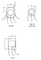
- Fig. 3A is a plan view of the buzzer shown in Fig. 2, and Fig. 3B is a plan view of a prior art buzzer.
- Fig. 4 is a plan view of another buzzer that may be used in a thermometer embodying this invention.
- Fig. 5 is an enlarged diagonal view of a portion of the thermometer of Fig. 1 where the buzzer is set.
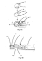
- Figs. 6A and 6B, together referred to as Fig. 6, are respectively an exploded
diagonal view of a portion of the sub-case, the buzzer and the buzzer to show their
positional relationship and a sectional view taken along
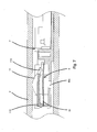
line 6B-6B of Fig. 6A. - Fig. 7 is an enlarged sectional view of a portion of the thermometer of Fig. 1 in the neighborhood of the buzzer.
-
- The invention is described next by way of an example. Fig. 1 shows an electronic thermometer 1 embodying this invention, comprising a
main body 2 which is elongated and has a front tip forming a temperature detecting part 3, abattery cover 4 which is detachably attached to the back end part of themain body 2, a display device (LCD) 5 for displaying the result of measurement, a push button 6 provided on the back surface of themain body 2 for starting the operation of the thermometer, and aninner unit 7 disposed inside themain body 2. As shown in Fig. 2, theinner unit 7 is formed with asub-case 8 having attached thereon abuzzer 9, a control circuit (with a PCB 10), abuzzer cover 11, thedisplay device 5, abattery 12, lead lines and terminals (not shown) for connecting these components electrically, and a thermocouple (not shown) serving as the aforementioned temperature detecting part 3. - As the push button 6 is pressed, the control circuit carries out an initialization process. When the thermometer 1 is ready to take a measurement, an output to this effect is made through the
display device 5 and thebuzzer 9. As the temperature detecting part 3 is held in the armpit of a patient or inserted under the tongue, the control circuit starts a temperature-measuring process and calculates a temperature value from the temperature detected by the temperature detecting part 3. When the measurement process is completed, the end of the process is communicated by thebuzzer 9, and the calculated temperature value is displayed on thedisplay device 5. - As shown in Fig. 3A, the
buzzer 9 is formed mainly with apiezoelectric plate 90 and anoscillating plate 91, thepiezoelectric plate 90 being set above the oscillatingplate 91. Thepiezoelectric plate 90 is circular in shape, but theoscillating plate 91 is of a shape which may be described as a circle (with diameter L) from which mutually opposite arch-shaped portions 91a are removed (or as a rectangle with a pair of mutually opposite edges of length W replaced by outwardly protrudingarcs 91b of diameter L). This is to be compared with a traditional buzzer 9' with a circular piezoelectric plate 90' and a circular oscillating plate 91', as shown in Fig. 3B. The space for containing thebuzzer 9 inside thesub-case 8 is limited, as shown at 80 in Fig. 5. If its width is W, the diameter of the oscillating plate 91' could not be larger than W. According to this invention, by contrast, the separation between the two arch-shaped portions 91a must be reduced to W but its longitudinal dimension is not affected by the width of thespace 80. In other words, a buzzer larger than a circle of diameter W can be used according to this invention and the volume of the sound from the buzzer increases accordingly. - The shape of the buzzer as shown in Fig. 3A is not intended to limit the scope of the invention. Fig. 4 shows another
buzzer 109 with rectangular piezoelectric andoscillating plates - Figs. 5 and 6 show how the
buzzer 9 is assembled to theinner unit 7. Thebuzzer 9 is placed on asupport member 81 around the buzzer-containingspace 80 of thesub-case 8. A sound-conductingopening 80c is provided in thebottom surface 80a of thisspace 80. As thebuzzer 9 is placed on thesupport member 81, an empty space is formed surrounded by thebottom surface 80a, acylindrical side surface 80b and thebuzzer 9, serving as a resonance chamber when thebuzzer 9 is sounded, so as to increase the sound pressure of thebuzzer 9. In this example, the buzzer-containingspace 80 itself serves as a sound box. - The
buzzer cover 11, serving as means for holding thebuzzer 9 securely, is disposed above thebuzzer 9 placed in the buzzer-containingspace 80 of thesub-case 8. Thesupport member 81 is formed so as to support the entire peripheral edge portions of theoscillating plate 91, as shown in Fig. 5. Thebuzzer cover 11, on the other hand, is formed such that itsrim part 110 contacts only thearcuate portions 91b (shown in Fig. 3A). Thus, when thebuzzer 9 is activated, theoscillating plate 91 oscillates under this boundary condition with only the mutually opposite end edges in its longitudinal direction secured. - Thus, the points of maximum amplitude of oscillation, when the buzzer oscillates in its primary characteristic mode, lie on a line which is at an equal distance from the innermost positions of the side surfaces fastened by the contact with the
buzzer cover 11. As a result, the area of maximum amplitude of oscillation becomes much larger than if the entire peripheral edge portions are fastened according to the prior art technology. In other words, a far greater sound conversion efficiency can be attained according to this invention. - Although the invention has been described above by way of only one example, this example is not intended to limit the scope of the invention. Many modifications and variations are possible within the scope of the invention. Although an example was shown above wherein the
oscillating plate 91 of thebuzzer 9 is fastened at both end positions by designing the shape of thebuzzer cover 11 accordingly, thesupport member 81 around the buzzer-containingspace 80 may be designed in a shape so as to contact only thearcuate portions 91b of theoscillating plate 91. As still another example, both thebuzzer cover 11 and thesupport member 81 may be designed such that they both contact theoscillating plate 91 only along thearcuate edge portions 91b. - As shown in Fig. 6A, buzzer cover 11 may have an
opening 11a formed at one extreme edge position in its longitudinal direction for passing lead line therethrough for electrically connecting thebuzzer 9 with thePCB 10. In other words, as shown by this example, it is not necessary for obtaining the effect of this invention that the buzzer should be secured along its extreme edges as long as therim part 110 secures theoscillating plate 91 so as to allow it to undergo oscillations in a mode of oscillation under the condition of being supported at both its mutually opposite end parts. - Fig. 7 shows the
inner unit 7 inserted inside themain body 2. In this situation, thebuzzer cover 11 is in contact with the inner surface of themain body 2. This serves not only to further increase the sound pressure inside the resonance chamber formed by the buzzer-containingspace 80 but also to improve the transmission of sound by causing the vibrations of thebuzzer 9 to propagate through themain body 2 and through thebuzzer cover 11. - In summary, the sound effect of the buzzer can be improved according to this invention without adversely affecting the manner of using the thermometer, the ease of assembly or the water-proof characteristic.
Claims (15)
- An electronic thermometer comprising:a main body including a temperature detecting part;means for detecting and displaying temperature of said temperature detecting part;a buzzer that is elongated in a longitudinal direction, having a pair of mutually opposite end parts in said longitudinal direction; anda support structure contained inside said main body, said support structure securely supporting said buzzer only at said end parts of said buzzer.
- The electronic thermometer of claim 1 wherein said end parts of said buzzer are arcuately shaped.
- The electronic thermometer of claim 1 wherein said support structure has support members which contact said buzzer only at said end parts.
- The electronic thermometer of claim 1 wherein said support structure contains a control circuit including a driving circuit for said buzzer.
- The electronic thermometer of claim 3 wherein said support structure has a sound chamber with side surfaces and a bottom surface, said bottom surface being opposite said buzzer and having a sound-conducting opening, said support members being along said side surfaces.
- The electronic thermometer of claim 1 further comprising a buzzer-securing member for securing said buzzer, said buzzer-securing member having contact parts that contact said buzzer only at said end parts in a direction opposite said support structure.
- The electronic thermometer of claim 2 further comprising a buzzer-securing member for securing said buzzer, said buzzer-securing member having contact parts that contact said buzzer only at said end parts in a direction opposite said support structure.
- The electronic thermometer of claim 3 further comprising a buzzer-securing member for securing said buzzer, said buzzer-securing member having contact parts that contact said buzzer only at said end parts in a direction opposite said support structure.
- The electronic thermometer of claim 4 further comprising a buzzer-securing member for securing said buzzer, said buzzer-securing member having contact parts that contact said buzzer only at said end parts in a direction opposite said support structure.
- The electronic thermometer of claim 5 further comprising a buzzer-securing member for securing said buzzer, said buzzer-securing member having contact parts that contact said buzzer only at said end parts in a direction opposite said support structure.
- The electronic thermometer of claim 6 wherein said buzzer-securing member contacts also said main body.
- The electronic thermometer of claim 7 wherein said buzzer-securing member contacts also said main body.
- The electronic thermometer of claim 8 wherein said buzzer-securing member contacts also said main body.
- The electronic thermometer of claim 9 wherein said buzzer-securing member contacts also said main body.
- The electronic thermometer of claim 10 wherein said buzzer-securing member contacts also said main body.
Applications Claiming Priority (2)
| Application Number | Priority Date | Filing Date | Title |
|---|---|---|---|
| JP2002172177 | 2002-06-13 | ||
| JP2002172177A JP4203899B2 (en) | 2002-06-13 | 2002-06-13 | Electronic thermometer |
Publications (3)
| Publication Number | Publication Date |
|---|---|
| EP1371959A2 true EP1371959A2 (en) | 2003-12-17 |
| EP1371959A3 EP1371959A3 (en) | 2004-07-21 |
| EP1371959B1 EP1371959B1 (en) | 2014-06-11 |
Family
ID=29561789
Family Applications (1)
| Application Number | Title | Priority Date | Filing Date |
|---|---|---|---|
| EP03009535.0A Expired - Lifetime EP1371959B1 (en) | 2002-06-13 | 2003-04-28 | Electronic clinical thermometer |
Country Status (5)
| Country | Link |
|---|---|
| US (1) | US6966694B2 (en) |
| EP (1) | EP1371959B1 (en) |
| JP (1) | JP4203899B2 (en) |
| CN (1) | CN1247971C (en) |
| TW (1) | TW590760B (en) |
Cited By (1)
| Publication number | Priority date | Publication date | Assignee | Title |
|---|---|---|---|---|
| EP1857798A1 (en) * | 2006-05-18 | 2007-11-21 | Omron Healthcare Co., Ltd. | Electronic thermometer |
Families Citing this family (11)
| Publication number | Priority date | Publication date | Assignee | Title |
|---|---|---|---|---|
| US7393137B2 (en) * | 2003-09-30 | 2008-07-01 | Citizen Holdings Co. Ltd. | Clinical thermometer |
| CA116310S (en) * | 2004-06-09 | 2006-08-24 | Omron Healthcare Co Ltd | Electric thermometer |
| USD521881S1 (en) * | 2004-09-24 | 2006-05-30 | Kirkbride Don J | Thermometer with flavored tip |
| US20070025416A1 (en) * | 2005-07-27 | 2007-02-01 | Hui-Ming Chen | Clinical thermometer |
| US7597668B2 (en) * | 2006-05-31 | 2009-10-06 | Medisim Ltd. | Non-invasive temperature measurement |
| US20080075143A1 (en) * | 2006-09-21 | 2008-03-27 | Vanessa Lampke-Honeyghan | Digital thermometers with audible feedback |
| US8185341B2 (en) | 2008-05-30 | 2012-05-22 | Medisim Ltd. | Surface temperature profile |
| JP5357003B2 (en) * | 2009-12-27 | 2013-12-04 | テルモ株式会社 | Electronic thermometer |
| CN102686991A (en) * | 2009-12-27 | 2012-09-19 | 泰尔茂株式会社 | Digital Thermometer |
| EP3568007B1 (en) * | 2017-01-16 | 2025-04-09 | Radio Systems Corporation | Piezoelectric detection coupling of a bark collar |
| USD852069S1 (en) * | 2019-03-12 | 2019-06-25 | Shenzhen Yingli Wannian Technology Co., Ltd. | Thermometer |
Citations (2)
| Publication number | Priority date | Publication date | Assignee | Title |
|---|---|---|---|---|
| US4579464A (en) | 1983-08-09 | 1986-04-01 | Terumo Kabushiki Kaisha | Electronic clinical thermometer |
| JP2539224B2 (en) | 1987-07-14 | 1996-10-02 | シチズン時計株式会社 | Waterproof electronic thermometer |
Family Cites Families (17)
| Publication number | Priority date | Publication date | Assignee | Title |
|---|---|---|---|---|
| US4157459A (en) * | 1977-10-19 | 1979-06-05 | Floyd Bell Associates Inc. | Electronic audio signalling device for telephones |
| US4282520A (en) * | 1978-10-25 | 1981-08-04 | Shipp John I | Piezoelectric horn and a smoke detector containing same |
| DE3013788C2 (en) * | 1980-04-10 | 1982-11-25 | Siemens AG, 1000 Berlin und 8000 München | Piezoceramic disc for a signal generator to generate an acoustic signal |
| EP0051832B1 (en) * | 1980-11-07 | 1985-02-27 | Hitachi, Ltd. | Piezoelectric ceramic transducer |
| JPS5834381A (en) * | 1981-08-25 | 1983-02-28 | Citizen Watch Co Ltd | Sounding body of electronic timepiece |
| US4602245A (en) * | 1983-04-29 | 1986-07-22 | Ensco, Inc. | General purpose modular acoustic signal generator |
| JPS6162831A (en) * | 1984-09-05 | 1986-03-31 | Citizen Watch Co Ltd | Electronic clinical thermometer with buzzer |
| GB2168875A (en) * | 1984-12-19 | 1986-06-25 | Philips Electronic Associated | Electroacoustic calling device |
| JP2527557Y2 (en) * | 1990-05-25 | 1997-03-05 | シチズン時計株式会社 | Structure of electronic thermometer |
| JP2949873B2 (en) * | 1991-02-22 | 1999-09-20 | 松下電器産業株式会社 | Piezoelectric buzzer |
| JPH04275594A (en) * | 1991-03-04 | 1992-10-01 | Toshiba Home Techno Kk | Driving device for piezoelectric buzzer |
| JPH07191679A (en) * | 1993-11-17 | 1995-07-28 | Terumo Corp | Piezoelectric buzzer sounding member |
| JP3256058B2 (en) * | 1993-12-24 | 2002-02-12 | テルモ株式会社 | Piezoelectric buzzer sounding body |
| JPH11248546A (en) * | 1998-03-05 | 1999-09-17 | Asahi Techno Glass Corp | Buzzer attachment structure for electronic thermometer |
| JP3134844B2 (en) * | 1998-06-11 | 2001-02-13 | 株式会社村田製作所 | Piezo acoustic components |
| JP3489509B2 (en) * | 1999-02-22 | 2004-01-19 | 株式会社村田製作所 | Electroacoustic transducer |
| US6394648B1 (en) * | 2000-11-22 | 2002-05-28 | K-Jump Health Co., Ltd. | Electronic thermometer |
-
2002
- 2002-06-13 JP JP2002172177A patent/JP4203899B2/en not_active Expired - Fee Related
-
2003
- 2003-04-28 EP EP03009535.0A patent/EP1371959B1/en not_active Expired - Lifetime
- 2003-05-19 CN CNB031364306A patent/CN1247971C/en not_active Expired - Lifetime
- 2003-05-30 US US10/449,981 patent/US6966694B2/en not_active Expired - Fee Related
- 2003-06-12 TW TW092115925A patent/TW590760B/en not_active IP Right Cessation
Patent Citations (2)
| Publication number | Priority date | Publication date | Assignee | Title |
|---|---|---|---|---|
| US4579464A (en) | 1983-08-09 | 1986-04-01 | Terumo Kabushiki Kaisha | Electronic clinical thermometer |
| JP2539224B2 (en) | 1987-07-14 | 1996-10-02 | シチズン時計株式会社 | Waterproof electronic thermometer |
Cited By (4)
| Publication number | Priority date | Publication date | Assignee | Title |
|---|---|---|---|---|
| EP1857798A1 (en) * | 2006-05-18 | 2007-11-21 | Omron Healthcare Co., Ltd. | Electronic thermometer |
| KR100883723B1 (en) | 2006-05-18 | 2009-02-12 | 오므론 헬스캐어 가부시키가이샤 | Electronic thermometer |
| US7547140B2 (en) | 2006-05-18 | 2009-06-16 | Omron Healthcare Co., Ltd. | Electronic thermometer |
| RU2425339C2 (en) * | 2006-05-18 | 2011-07-27 | Омрон Хэлткэа Ко., Лтд. | Electronic thermometre |
Also Published As
| Publication number | Publication date |
|---|---|
| CN1467489A (en) | 2004-01-14 |
| JP2004020241A (en) | 2004-01-22 |
| EP1371959B1 (en) | 2014-06-11 |
| JP4203899B2 (en) | 2009-01-07 |
| EP1371959A3 (en) | 2004-07-21 |
| TW590760B (en) | 2004-06-11 |
| TW200401624A (en) | 2004-02-01 |
| US20030231696A1 (en) | 2003-12-18 |
| US6966694B2 (en) | 2005-11-22 |
| CN1247971C (en) | 2006-03-29 |
Similar Documents
| Publication | Publication Date | Title |
|---|---|---|
| EP1371959B1 (en) | Electronic clinical thermometer | |
| EP0458420B1 (en) | Electronic clinical thermometer | |
| BRPI1101771A2 (en) | vibrating reed, vibrator, oscillator and electronic device | |
| US20050066736A1 (en) | Piezoelectric vibration sensor | |
| CN109217838B (en) | Resonator element, resonator, electronic device, electronic apparatus, and moving object | |
| US7234352B2 (en) | Angular velocity senor | |
| US4579464A (en) | Electronic clinical thermometer | |
| JP2005528834A (en) | Portable electronic devices | |
| JP2009300310A (en) | Electronic clinical thermometer | |
| JP2539224B2 (en) | Waterproof electronic thermometer | |
| JP2007093213A (en) | Pressure sensor | |
| US8226573B2 (en) | Thermometer probe | |
| JP2017026476A (en) | Electronics | |
| JPH1062328A (en) | Tactile sensor | |
| JP2019009619A (en) | Vibration element, vibrator, generator, electronic apparatus, and mobile body | |
| JPH02210233A (en) | Electronic clinical thermometer and its production | |
| KR960024284A (en) | Vibrating gyroscope | |
| JPS6068442U (en) | electronic thermometer | |
| CN210664791U (en) | Thermometer with improved buzzer structure | |
| KR20210148788A (en) | Bluetooth earphone with non-contact temperature measurement | |
| JP2003000557A (en) | Biological signal monitoring device | |
| JPH01229922A (en) | Electronic clinical thermometer | |
| JP4610817B2 (en) | Electronic equipment | |
| CN100390513C (en) | Electronic thermometer with sounding | |
| JP2002071470A (en) | Electronic clinical thermometer |
Legal Events
| Date | Code | Title | Description |
|---|---|---|---|
| PUAI | Public reference made under article 153(3) epc to a published international application that has entered the european phase |
Free format text: ORIGINAL CODE: 0009012 |
|
| AK | Designated contracting states |
Kind code of ref document: A2 Designated state(s): AT BE BG CH CY CZ DE DK EE ES FI FR GB GR HU IE IT LI LU MC NL PT RO SE SI SK TR |
|
| AX | Request for extension of the european patent |
Extension state: AL LT LV MK |
|
| RAP1 | Party data changed (applicant data changed or rights of an application transferred) |
Owner name: OMRON HEALTHCARE CO., LTD. |
|
| PUAL | Search report despatched |
Free format text: ORIGINAL CODE: 0009013 |
|
| AK | Designated contracting states |
Kind code of ref document: A3 Designated state(s): AT BE BG CH CY CZ DE DK EE ES FI FR GB GR HU IE IT LI LU MC NL PT RO SE SI SK TR |
|
| AX | Request for extension of the european patent |
Extension state: AL LT LV MK |
|
| RIC1 | Information provided on ipc code assigned before grant |
Ipc: 7G 01K 1/02 B Ipc: 7G 10K 9/00 B Ipc: 7H 01L 41/04 B Ipc: 7G 01K 13/00 A |
|
| RAP1 | Party data changed (applicant data changed or rights of an application transferred) |
Owner name: OMRON HEALTHCARE CO., LTD. |
|
| 17P | Request for examination filed |
Effective date: 20041006 |
|
| AKX | Designation fees paid |
Designated state(s): DE ES FR GB IT NL |
|
| 17Q | First examination report despatched |
Effective date: 20101025 |
|
| GRAJ | Information related to disapproval of communication of intention to grant by the applicant or resumption of examination proceedings by the epo deleted |
Free format text: ORIGINAL CODE: EPIDOSDIGR1 |
|
| GRAP | Despatch of communication of intention to grant a patent |
Free format text: ORIGINAL CODE: EPIDOSNIGR1 |
|
| INTG | Intention to grant announced |
Effective date: 20140121 |
|
| RIN1 | Information on inventor provided before grant (corrected) |
Inventor name: KITAGAWA, HIROKAZU Inventor name: OGAWA, HIROSHI Inventor name: MINAMIKAWA, SUSUMU Inventor name: KIHARA, MASAZUMI |
|
| GRAS | Grant fee paid |
Free format text: ORIGINAL CODE: EPIDOSNIGR3 |
|
| RAP1 | Party data changed (applicant data changed or rights of an application transferred) |
Owner name: OMRON HEALTHCARE CO., LTD. |
|
| GRAA | (expected) grant |
Free format text: ORIGINAL CODE: 0009210 |
|
| AK | Designated contracting states |
Kind code of ref document: B1 Designated state(s): DE ES FR GB IT NL |
|
| REG | Reference to a national code |
Ref country code: GB Ref legal event code: FG4D |
|
| REG | Reference to a national code |
Ref country code: DE Ref legal event code: R096 Ref document number: 60346312 Country of ref document: DE Effective date: 20140724 |
|
| REG | Reference to a national code |
Ref country code: NL Ref legal event code: VDEP Effective date: 20140611 |
|
| PG25 | Lapsed in a contracting state [announced via postgrant information from national office to epo] |
Ref country code: ES Free format text: LAPSE BECAUSE OF FAILURE TO SUBMIT A TRANSLATION OF THE DESCRIPTION OR TO PAY THE FEE WITHIN THE PRESCRIBED TIME-LIMIT Effective date: 20140611 |
|
| PG25 | Lapsed in a contracting state [announced via postgrant information from national office to epo] |
Ref country code: NL Free format text: LAPSE BECAUSE OF FAILURE TO SUBMIT A TRANSLATION OF THE DESCRIPTION OR TO PAY THE FEE WITHIN THE PRESCRIBED TIME-LIMIT Effective date: 20140611 |
|
| REG | Reference to a national code |
Ref country code: DE Ref legal event code: R097 Ref document number: 60346312 Country of ref document: DE |
|
| PLBE | No opposition filed within time limit |
Free format text: ORIGINAL CODE: 0009261 |
|
| STAA | Information on the status of an ep patent application or granted ep patent |
Free format text: STATUS: NO OPPOSITION FILED WITHIN TIME LIMIT |
|
| PG25 | Lapsed in a contracting state [announced via postgrant information from national office to epo] |
Ref country code: IT Free format text: LAPSE BECAUSE OF FAILURE TO SUBMIT A TRANSLATION OF THE DESCRIPTION OR TO PAY THE FEE WITHIN THE PRESCRIBED TIME-LIMIT Effective date: 20140611 |
|
| 26N | No opposition filed |
Effective date: 20150312 |
|
| REG | Reference to a national code |
Ref country code: DE Ref legal event code: R097 Ref document number: 60346312 Country of ref document: DE Effective date: 20150312 |
|
| GBPC | Gb: european patent ceased through non-payment of renewal fee |
Effective date: 20150428 |
|
| PG25 | Lapsed in a contracting state [announced via postgrant information from national office to epo] |
Ref country code: GB Free format text: LAPSE BECAUSE OF NON-PAYMENT OF DUE FEES Effective date: 20150428 |
|
| REG | Reference to a national code |
Ref country code: FR Ref legal event code: ST Effective date: 20151231 |
|
| PG25 | Lapsed in a contracting state [announced via postgrant information from national office to epo] |
Ref country code: FR Free format text: LAPSE BECAUSE OF NON-PAYMENT OF DUE FEES Effective date: 20150430 |
|
| PGFP | Annual fee paid to national office [announced via postgrant information from national office to epo] |
Ref country code: DE Payment date: 20210429 Year of fee payment: 19 |
|
| REG | Reference to a national code |
Ref country code: DE Ref legal event code: R119 Ref document number: 60346312 Country of ref document: DE |
|
| PG25 | Lapsed in a contracting state [announced via postgrant information from national office to epo] |
Ref country code: DE Free format text: LAPSE BECAUSE OF NON-PAYMENT OF DUE FEES Effective date: 20221103 |