EP1371842A1 - Anti-bounce needle valve for a fuel injector - Google Patents
Anti-bounce needle valve for a fuel injector Download PDFInfo
- Publication number
- EP1371842A1 EP1371842A1 EP03008106A EP03008106A EP1371842A1 EP 1371842 A1 EP1371842 A1 EP 1371842A1 EP 03008106 A EP03008106 A EP 03008106A EP 03008106 A EP03008106 A EP 03008106A EP 1371842 A1 EP1371842 A1 EP 1371842A1
- Authority
- EP
- European Patent Office
- Prior art keywords
- needle
- bounce
- fuel injector
- shot
- valve seat
- Prior art date
- Legal status (The legal status is an assumption and is not a legal conclusion. Google has not performed a legal analysis and makes no representation as to the accuracy of the status listed.)
- Granted
Links
Images

Classifications
-
- F—MECHANICAL ENGINEERING; LIGHTING; HEATING; WEAPONS; BLASTING
- F02—COMBUSTION ENGINES; HOT-GAS OR COMBUSTION-PRODUCT ENGINE PLANTS
- F02M—SUPPLYING COMBUSTION ENGINES IN GENERAL WITH COMBUSTIBLE MIXTURES OR CONSTITUENTS THEREOF
- F02M61/00—Fuel-injectors not provided for in groups F02M39/00 - F02M57/00 or F02M67/00
- F02M61/16—Details not provided for in, or of interest apart from, the apparatus of groups F02M61/02 - F02M61/14
-
- F—MECHANICAL ENGINEERING; LIGHTING; HEATING; WEAPONS; BLASTING
- F02—COMBUSTION ENGINES; HOT-GAS OR COMBUSTION-PRODUCT ENGINE PLANTS
- F02M—SUPPLYING COMBUSTION ENGINES IN GENERAL WITH COMBUSTIBLE MIXTURES OR CONSTITUENTS THEREOF
- F02M61/00—Fuel-injectors not provided for in groups F02M39/00 - F02M57/00 or F02M67/00
- F02M61/16—Details not provided for in, or of interest apart from, the apparatus of groups F02M61/02 - F02M61/14
- F02M61/20—Closing valves mechanically, e.g. arrangements of springs or weights or permanent magnets; Damping of valve lift
-
- F—MECHANICAL ENGINEERING; LIGHTING; HEATING; WEAPONS; BLASTING
- F02—COMBUSTION ENGINES; HOT-GAS OR COMBUSTION-PRODUCT ENGINE PLANTS
- F02M—SUPPLYING COMBUSTION ENGINES IN GENERAL WITH COMBUSTIBLE MIXTURES OR CONSTITUENTS THEREOF
- F02M2200/00—Details of fuel-injection apparatus, not otherwise provided for
- F02M2200/30—Fuel-injection apparatus having mechanical parts, the movement of which is damped
- F02M2200/306—Fuel-injection apparatus having mechanical parts, the movement of which is damped using mechanical means
-
- F—MECHANICAL ENGINEERING; LIGHTING; HEATING; WEAPONS; BLASTING
- F02—COMBUSTION ENGINES; HOT-GAS OR COMBUSTION-PRODUCT ENGINE PLANTS
- F02M—SUPPLYING COMBUSTION ENGINES IN GENERAL WITH COMBUSTIBLE MIXTURES OR CONSTITUENTS THEREOF
- F02M61/00—Fuel-injectors not provided for in groups F02M39/00 - F02M57/00 or F02M67/00
- F02M61/04—Fuel-injectors not provided for in groups F02M39/00 - F02M57/00 or F02M67/00 having valves, e.g. having a plurality of valves in series
- F02M61/10—Other injectors with elongated valve bodies, i.e. of needle-valve type
-
- F—MECHANICAL ENGINEERING; LIGHTING; HEATING; WEAPONS; BLASTING
- F02—COMBUSTION ENGINES; HOT-GAS OR COMBUSTION-PRODUCT ENGINE PLANTS
- F02M—SUPPLYING COMBUSTION ENGINES IN GENERAL WITH COMBUSTIBLE MIXTURES OR CONSTITUENTS THEREOF
- F02M61/00—Fuel-injectors not provided for in groups F02M39/00 - F02M57/00 or F02M67/00
- F02M61/16—Details not provided for in, or of interest apart from, the apparatus of groups F02M61/02 - F02M61/14
- F02M61/166—Selection of particular materials
Definitions
- the present invention relates to fuel injectors used for internal combustion engines, and more particularly to the needle valve thereof. Still more particularly, the present invention relates to a needle valve of the aforesaid type having an anti-bounce feature.
- Internal combustion engines particularly diesel engines, utilize fuel injection systems for providing precise metering of fuel to each cylinder, thereby enhancing performance and fuel economy, as well as reduction of undesirable emissions.
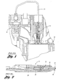
- a typical conventional application of a fuel injector 10 with respect to a diesel internal combustion engine 12 is shown at Figures 1 and 2.
- a source of pressurized fuel 14 is connected by a fuel line 16 to the fuel injector 10.
- the fuel injector 10 includes a tip body 18, a needle valve 20 including a needle 22 and valve seat 24, and a needle spring 26 which biases the needle seatably upon the valve seat.
- Pressurized fuel passes along a passage 28 of the fuel injector and upon a predetermined level of pressure being attained, the needle 22 moves against the biasing of the needle spring 26, thereby opening the needle valve seat 20, whereby fuel injects into the cylinder.
- the needle 22 is biased by the needle spring 26 so as to again close the needle valve 20.
- the movements of the needle 22 are very rapid, and when the needle closes upon the valve seat 24, a percussion occurs.
- the closure percussion involves a tendency of the needle 22 to bounce at the valve seat 24, with the undesirable consequences of undue seat wear and a second fuel injection occurring during the bounce.
- the bounce induced fuel injection involves an unwanted low pressure fuel injection late in the combustion cycle which can adversely affect fuel economy and performance and increase undesirable emissions.
- closure percussion bounce relates to the metallic components of the needle and the valve seat colliding in an essentially elastic manner. As such, there is a substantial conservation of kinetic energy which translates into bounce of the needle.
- the present invention is an anti-bounce needle for use in a needle valve of a fuel injector, wherein the anti-bounce needle inherently incorporates the anti-bounce feature.
- the anti-bounce needle according to the present invention has a conventionally configured exterior for interfacing with a valve seat of the needle valve with the tip body of a conventional fuel injector.
- the anti-bounce needle is characterized by a needle body having an interior cavity which is filled with small diameter shot, preferably generally spherical tungsten carbide shot.
- the shot causes the needle collision with the valve seat to be inelastic, thereby rendering the kinetic energy of the impact to be non-conserved (transformed to heat) such that no bouncing of the needle with respect to the valve seat can occur.
- an object of the present invention to provide an anti-bounce needle of a needle valve for a fuel injector.
- Figure 1 is a broken-away, partly sectional side view of a diesel engine having a conventional fuel injector.
- Figure 2 is a sectional side view of the conventional fuel injector of Figure 1.
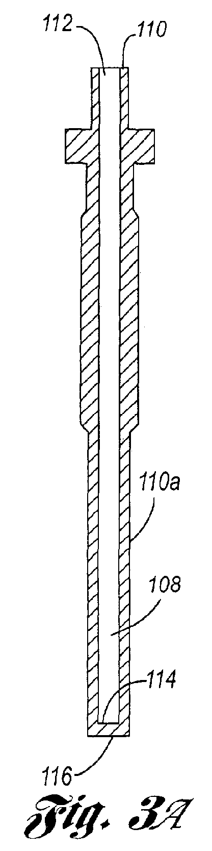
- Figure 3A is a sectional view of an anti-bounce needle according to the present invention at a first stage of fabrication.
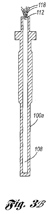
- Figure 3B is a sectional view of an anti-bounce needle according to the present invention at an intermediate stage of fabrication.
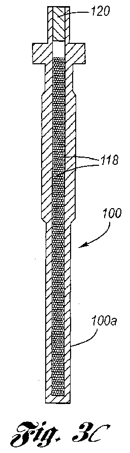
- Figure 3C is a sectional view of an anti-bounce needle according to the present invention at a final stage of fabrication.
- Figure 4 is a partly sectional side view of an anti-bounce needle according to the present invention shown seated in a tip body of a conventional fuel injector.
- Figure 5 is a partly sectional view seen along line 5-5 in Figure 4.
- Figure 6 is a partly sectional view seen along line 6-6 in Figure 4.
- Figures 3A through 6 depict an example of an anti-bounce needle 100 for a needle valve 102 of a fuel injector of an internal combustion engine.
- the anti-bounce needle 100 is configured as appropriate for usage in a fuel injector tip body 104 with respect to a valve seat 106 thereof.
- the anti-bounce needle 100 is composed of a material, and is externally configured, per that of a conventional needle.
- the anti-bounce needle 100 has a needle body 100a having an interior cavity 108 formed therein, as for example by boring or other fabrication technique.
- the interior cavity 108 runs from the aft end 110 of the anti-bounce needle 100, whereat is formed an opening 112, and terminates in a blind end 114 at the fore end 116 of the anti-bounce needle (the fore end of the needle interfaces with the needle seat).
- a multiplicity of loose shot 118 is introduced fillingly into the interior cavity 108 via the opening 112 thereof.
- the shot 118 is preferably tungsten carbide shot having a small radius (for example, the shot may have a radius of about an order of magnitude smaller than the diameter of the anti-bounce needle).
- a plug 120 is placed in the interior cavity 108 at the aft end 110 of the needle 100.
- the plug 120 is fixed securely and immovably to the anti-bounce needle 100, as for example by a press-fit, adhesive or weld.
- the shot fills at least a substantial portion of the interior cavity such as to be loosely distributed inside.
- the anti-bounce needle 100 is fitted into the fuel injector tip body 104, wherein the anti-bounce needle seats with respect to the valve seat 106.
- the shot 118 causes the needle collision with the valve seat to be inelastic such that there is no bounce of the anti-bounce needle.
- KE 1 KE 2 + Q
- KE 1 is the kinetic energy (1 ⁇ 2m(v 1 ) 2 ) of a moving object (the anti-bounce needle) before collision with an immovable target object (the valve seat)
- KE 2 is the kinetic energy (1 ⁇ 2m(v 2 ) 2 ) of the moving object (the anti-bounce needle) after collision with the immovable target object (the valve seat)
- Q is an amount of heat (and sound energy) generated by the collision.
- the collision is generally elastic such that Q is small, and since the valve seat is immovable, V 2 is large and must be damped by bounce into the spring and/or a conventional hydraulic assist system.
- the change of momentum of the shot is spread out over time such that the collision is substantially inelastic, wherein Q is large and V 2 is vanishing such that there is no bounce of the needle. This principle of operation is similar to that employed by dead blow hammers.
Landscapes
- Engineering & Computer Science (AREA)
- Chemical & Material Sciences (AREA)
- Combustion & Propulsion (AREA)
- Mechanical Engineering (AREA)
- General Engineering & Computer Science (AREA)
- Fuel-Injection Apparatus (AREA)
Abstract
Description
- The present invention relates to fuel injectors used for internal combustion engines, and more particularly to the needle valve thereof. Still more particularly, the present invention relates to a needle valve of the aforesaid type having an anti-bounce feature.
- Internal combustion engines, particularly diesel engines, utilize fuel injection systems for providing precise metering of fuel to each cylinder, thereby enhancing performance and fuel economy, as well as reduction of undesirable emissions.
- A typical conventional application of a
fuel injector 10 with respect to a dieselinternal combustion engine 12 is shown at Figures 1 and 2. A source of pressurizedfuel 14 is connected by afuel line 16 to thefuel injector 10. As best seen at Figure 2, thefuel injector 10 includes atip body 18, aneedle valve 20 including aneedle 22 andvalve seat 24, and aneedle spring 26 which biases the needle seatably upon the valve seat. Pressurized fuel passes along apassage 28 of the fuel injector and upon a predetermined level of pressure being attained, theneedle 22 moves against the biasing of theneedle spring 26, thereby opening theneedle valve seat 20, whereby fuel injects into the cylinder. When the pressurized fuel drops below a second predetermined level, theneedle 22 is biased by theneedle spring 26 so as to again close theneedle valve 20. The movements of theneedle 22 are very rapid, and when the needle closes upon thevalve seat 24, a percussion occurs. - Engine performance, fuel economy and emissions all depend upon precise timing of the start and end of the fuel injection event. In this regard, it is desirable for the beginning and end of the fuel injection event to be as rapid as possible.
- The closure percussion involves a tendency of the
needle 22 to bounce at thevalve seat 24, with the undesirable consequences of undue seat wear and a second fuel injection occurring during the bounce. The bounce induced fuel injection involves an unwanted low pressure fuel injection late in the combustion cycle which can adversely affect fuel economy and performance and increase undesirable emissions. - The origin of closure percussion bounce relates to the metallic components of the needle and the valve seat colliding in an essentially elastic manner. As such, there is a substantial conservation of kinetic energy which translates into bounce of the needle.
- Conventionally, fuel injector manufacturers have struggled with needle bounce, and have attempted to solve this problem by incorporating hydraulic assist systems which serve to assuage needle bounce. Problematically, these hydraulic systems are complex and costly.
- Accordingly, what is needed is a fuel injector needle valve in which the needle valve inherently has an absence of bounce.
- The present invention is an anti-bounce needle for use in a needle valve of a fuel injector, wherein the anti-bounce needle inherently incorporates the anti-bounce feature.
- The anti-bounce needle according to the present invention has a conventionally configured exterior for interfacing with a valve seat of the needle valve with the tip body of a conventional fuel injector. The anti-bounce needle is characterized by a needle body having an interior cavity which is filled with small diameter shot, preferably generally spherical tungsten carbide shot.
- In operation, when the anti-bounce needle impacts upon the valve seat at the conclusion of a fuel injection process, the shot causes the needle collision with the valve seat to be inelastic, thereby rendering the kinetic energy of the impact to be non-conserved (transformed to heat) such that no bouncing of the needle with respect to the valve seat can occur.
- Accordingly, it is an object of the present invention to provide an anti-bounce needle of a needle valve for a fuel injector.
- This and additional objects, features and advantages of the present invention will become clearer from the following specification of a preferred embodiment.
- Figure 1 is a broken-away, partly sectional side view of a diesel engine having a conventional fuel injector.
- Figure 2 is a sectional side view of the conventional fuel injector of Figure 1.
- Figure 3A is a sectional view of an anti-bounce needle according to the present invention at a first stage of fabrication.
- Figure 3B is a sectional view of an anti-bounce needle according to the present invention at an intermediate stage of fabrication.
- Figure 3C is a sectional view of an anti-bounce needle according to the present invention at a final stage of fabrication.
- Figure 4 is a partly sectional side view of an anti-bounce needle according to the present invention shown seated in a tip body of a conventional fuel injector.
- Figure 5 is a partly sectional view seen along line 5-5 in Figure 4.
- Figure 6 is a partly sectional view seen along line 6-6 in Figure 4.
- Referring now to the drawings, Figures 3A through 6 depict an example of an
anti-bounce needle 100 for aneedle valve 102 of a fuel injector of an internal combustion engine. Theanti-bounce needle 100 is configured as appropriate for usage in a fuelinjector tip body 104 with respect to avalve seat 106 thereof. For example, theanti-bounce needle 100 is composed of a material, and is externally configured, per that of a conventional needle. - As shown at Figure 3A, the
anti-bounce needle 100 has aneedle body 100a having aninterior cavity 108 formed therein, as for example by boring or other fabrication technique. Theinterior cavity 108 runs from theaft end 110 of theanti-bounce needle 100, whereat is formed anopening 112, and terminates in ablind end 114 at thefore end 116 of the anti-bounce needle (the fore end of the needle interfaces with the needle seat). - As shown at Figure 3B, a multiplicity of
loose shot 118 is introduced fillingly into theinterior cavity 108 via theopening 112 thereof. Theshot 118 is preferably tungsten carbide shot having a small radius (for example, the shot may have a radius of about an order of magnitude smaller than the diameter of the anti-bounce needle). - As shown at Figure 3C, a
plug 120 is placed in theinterior cavity 108 at theaft end 110 of theneedle 100. Theplug 120 is fixed securely and immovably to theanti-bounce needle 100, as for example by a press-fit, adhesive or weld. Upon placement of theplug 120, the shot fills at least a substantial portion of the interior cavity such as to be loosely distributed inside. - As shown at Figure 4, after fabrication, the
anti-bounce needle 100 is fitted into the fuelinjector tip body 104, wherein the anti-bounce needle seats with respect to thevalve seat 106. - In operation, when the anti-bounce needle impacts upon the valve seat at the conclusion of a fuel injection process, the
shot 118 causes the needle collision with the valve seat to be inelastic such that there is no bounce of the anti-bounce needle. - It is believed that the underlying principle of operation is as follows. Although momentum is conserved in any collision, the kinetic energy need not be conserved. Consider a moving object and a target object which is immovable. In a perfectly elastic collision, kinetic energy is conserved so that upon collision, the moving object bounces off the target object. On the other hand, if the collision is perfectly inelastic, upon collision, the moving object will stop at the target object and not bounce. Generally, for any collision, the energy terms may be represented by:
- In a conventional fuel injector needle collision with its valve seat, the collision is generally elastic such that Q is small, and since the valve seat is immovable, V2 is large and must be damped by bounce into the spring and/or a conventional hydraulic assist system. However, in the anti-bounce needle according to the present invention, the change of momentum of the shot is spread out over time such that the collision is substantially inelastic, wherein Q is large and V2 is vanishing such that there is no bounce of the needle. This principle of operation is similar to that employed by dead blow hammers.
- To those skilled in the art to which this invention appertains, the above described preferred embodiment may be subject to change or modification. Such change or modification can be carried out without departing from the scope of the invention, which is intended to be limited only by the scope of the appended claims.
Claims (6)
- An anti-bounce needle for a fuel injector, comprising:a needle body having an interior cavity; anda multiplicity of shot loosely distributed in said interior cavity.
- The anti-bounce needle of Claim 1, wherein said shot is composed of tungsten carbide.
- The anti-bounce needle of Claim 2, wherein said shot is generally small diametered compared to a diameter of said interior cavity.
- A fuel injector, comprising:a fuel injector tip body;a valve seat formed in said tip body;an anti-bounce needle located in said tip body, said anti-bounce needle comprising:a needle body having an interior cavity; anda multiplicity of shot loosely distributed in said interior cavity; anda needle spring for biasing said anti-bounce needle seatably with respect to said valve seat.
- The fuel injector of Claim 4, wherein said shot is composed of tungsten carbide.
- The fuel injector of Claim 5, wherein said shot is generally small diametered compared to a diameter of said interior cavity.
Applications Claiming Priority (2)
| Application Number | Priority Date | Filing Date | Title |
|---|---|---|---|
| US10/166,885 US6874703B2 (en) | 2002-06-11 | 2002-06-11 | Anti-bounce needle valve for a fuel injector |
| US166885 | 2002-06-11 |
Publications (2)
| Publication Number | Publication Date |
|---|---|
| EP1371842A1 true EP1371842A1 (en) | 2003-12-17 |
| EP1371842B1 EP1371842B1 (en) | 2006-06-21 |
Family
ID=29583743
Family Applications (1)
| Application Number | Title | Priority Date | Filing Date |
|---|---|---|---|
| EP03008106A Expired - Lifetime EP1371842B1 (en) | 2002-06-11 | 2003-04-07 | Anti-bounce needle valve for a fuel injector |
Country Status (6)
| Country | Link |
|---|---|
| US (1) | US6874703B2 (en) |
| EP (1) | EP1371842B1 (en) |
| AT (1) | ATE331136T1 (en) |
| BR (1) | BR0301558A (en) |
| DE (1) | DE60306265T2 (en) |
| MX (1) | MXPA03004484A (en) |
Cited By (2)
| Publication number | Priority date | Publication date | Assignee | Title |
|---|---|---|---|---|
| EP1703120A1 (en) * | 2005-02-24 | 2006-09-20 | Mitsubishi Heavy Industries, Ltd. | Electromagnetic controlled fuel injection apparatus with poppet valve |
| EP2363592A1 (en) * | 2010-02-25 | 2011-09-07 | Continental Automotive GmbH | Injection valve |
Families Citing this family (2)
| Publication number | Priority date | Publication date | Assignee | Title |
|---|---|---|---|---|
| JP6488134B2 (en) * | 2015-01-26 | 2019-03-20 | 日立オートモティブシステムズ株式会社 | Fuel injection valve |
| US11480129B2 (en) | 2021-02-19 | 2022-10-25 | Caterpillar Inc. | Fuel system and fuel injector control strategy for stabilized injection control valve closing |
Citations (5)
| Publication number | Priority date | Publication date | Assignee | Title |
|---|---|---|---|---|
| DE3314899A1 (en) * | 1983-04-25 | 1984-10-25 | Mesenich, Gerhard, Dipl.-Ing., 4630 Bochum | SPRING ARRANGEMENT WITH ADDITIONAL DIMENSIONS FOR IMPROVING THE DYNAMIC BEHAVIOR OF ELECTROMAGNET SYSTEMS |
| US5284302A (en) * | 1992-02-12 | 1994-02-08 | Nippondenso Co., Ltd. | Fuel injection valve |
| DE4332117A1 (en) * | 1993-09-22 | 1995-03-23 | Bosch Gmbh Robert | Solenoid valve |
| WO1996009473A1 (en) * | 1994-09-20 | 1996-03-28 | Siemens Automotive Corporation | Notched needle bounce eliminator |
| DE10060290A1 (en) * | 2000-12-05 | 2002-06-06 | Bosch Gmbh Robert | Fuel injector |
Family Cites Families (7)
| Publication number | Priority date | Publication date | Assignee | Title |
|---|---|---|---|---|
| DE3105686A1 (en) * | 1981-02-17 | 1982-09-02 | Robert Bosch Gmbh, 7000 Stuttgart | "FUEL INJECTION NOZZLE" |
| DE3120060A1 (en) * | 1981-05-20 | 1982-12-09 | Robert Bosch Gmbh, 7000 Stuttgart | FUEL INJECTION NOZZLE FOR INTERNAL COMBUSTION ENGINES |
| US4706788A (en) * | 1985-04-15 | 1987-11-17 | Melles Griot, Irvine Company | Vibration damped apparatus |
| DE4200710C1 (en) * | 1992-01-14 | 1993-06-09 | Robert Bosch Gmbh, 7000 Stuttgart, De | Nozzle for injection of fuel into IC engine - utilises implosion of cavitation bubbles leaving passage contg. porous plug of sinter, whisker or ceramic foam |
| DE19546033A1 (en) * | 1995-12-09 | 1997-06-12 | Bosch Gmbh Robert | Fuel injection valve for internal combustion engines |
| GB9714647D0 (en) * | 1997-07-12 | 1997-09-17 | Lucas Ind Plc | Injector |
| US6311582B1 (en) | 2000-10-26 | 2001-11-06 | Howard Chow | Deadblow claw hammer |
-
2002
- 2002-06-11 US US10/166,885 patent/US6874703B2/en not_active Expired - Lifetime
-
2003
- 2003-04-07 AT AT03008106T patent/ATE331136T1/en active
- 2003-04-07 DE DE60306265T patent/DE60306265T2/en not_active Expired - Lifetime
- 2003-04-07 EP EP03008106A patent/EP1371842B1/en not_active Expired - Lifetime
- 2003-05-12 BR BR0301558-0A patent/BR0301558A/en not_active Application Discontinuation
- 2003-05-21 MX MXPA03004484A patent/MXPA03004484A/en active IP Right Grant
Patent Citations (5)
| Publication number | Priority date | Publication date | Assignee | Title |
|---|---|---|---|---|
| DE3314899A1 (en) * | 1983-04-25 | 1984-10-25 | Mesenich, Gerhard, Dipl.-Ing., 4630 Bochum | SPRING ARRANGEMENT WITH ADDITIONAL DIMENSIONS FOR IMPROVING THE DYNAMIC BEHAVIOR OF ELECTROMAGNET SYSTEMS |
| US5284302A (en) * | 1992-02-12 | 1994-02-08 | Nippondenso Co., Ltd. | Fuel injection valve |
| DE4332117A1 (en) * | 1993-09-22 | 1995-03-23 | Bosch Gmbh Robert | Solenoid valve |
| WO1996009473A1 (en) * | 1994-09-20 | 1996-03-28 | Siemens Automotive Corporation | Notched needle bounce eliminator |
| DE10060290A1 (en) * | 2000-12-05 | 2002-06-06 | Bosch Gmbh Robert | Fuel injector |
Cited By (3)
| Publication number | Priority date | Publication date | Assignee | Title |
|---|---|---|---|---|
| EP1703120A1 (en) * | 2005-02-24 | 2006-09-20 | Mitsubishi Heavy Industries, Ltd. | Electromagnetic controlled fuel injection apparatus with poppet valve |
| US7350539B2 (en) | 2005-02-24 | 2008-04-01 | Mitsubishi Heavy Industries, Ltd. | Electromagnetic controlled fuel injection apparatus with poppet valve |
| EP2363592A1 (en) * | 2010-02-25 | 2011-09-07 | Continental Automotive GmbH | Injection valve |
Also Published As
| Publication number | Publication date |
|---|---|
| ATE331136T1 (en) | 2006-07-15 |
| EP1371842B1 (en) | 2006-06-21 |
| US6874703B2 (en) | 2005-04-05 |
| MXPA03004484A (en) | 2003-12-16 |
| BR0301558A (en) | 2004-09-08 |
| US20030226911A1 (en) | 2003-12-11 |
| DE60306265T2 (en) | 2007-05-31 |
| DE60306265D1 (en) | 2006-08-03 |
Similar Documents
| Publication | Publication Date | Title |
|---|---|---|
| US6076508A (en) | Fuel injection control device | |
| US5771865A (en) | Fuel injection system of an engine and a control method therefor | |
| USRE34999E (en) | Hole type fuel injector and injection method | |
| JP3885888B2 (en) | Common rail system | |
| US11300068B1 (en) | Fuel system for retarded armature lifting speed and fuel system operating method | |
| US6896208B2 (en) | Fuel injection system for an internal combustion engine | |
| US6874703B2 (en) | Anti-bounce needle valve for a fuel injector | |
| JP2001512552A (en) | Electronic control system and method for controlling fuel injection into engine by hydraulically actuated electronically controlled injection fuel system | |
| US5413281A (en) | Fuel injection nozzle for an internal combustion engine | |
| US20080296415A1 (en) | Valve Body, Fluid Injector and Process for Manufacturing a Valve Body | |
| US5033443A (en) | Pilot injection device for fuel injection pump | |
| JP2003530503A (en) | Fuel injection valve | |
| JPH11201000A (en) | Fuel injection system reinforced its tip member | |
| RU2168055C2 (en) | Fuel injector at spill-free fuel feed | |
| US6973918B2 (en) | Fuel injection device for an internal combustion engine | |
| US6390121B1 (en) | Check valve controlled by differential pressure | |
| JPH0842422A (en) | Injection valve for fuel injector of internal combustion engine,particularly diesel engine | |
| US20070278329A1 (en) | Valve Body And Fluid Injector With A Valve Body | |
| JPH1193800A (en) | Accumulator fuel injection valve | |
| EP1794442B1 (en) | Fuel injector with vop loss resistant valve spring for emissions-compliant engine applications i | |
| KR100412597B1 (en) | Fuel pressure control device for injector | |
| KR100394857B1 (en) | Injector for direct injection type diesel engine | |
| US7891587B2 (en) | Intermediate plate for a fuel injector, and fuel injector | |
| US20060219802A1 (en) | Fuel injection system for an internal combustion engine | |
| JPH0222235B2 (en) |
Legal Events
| Date | Code | Title | Description |
|---|---|---|---|
| PUAI | Public reference made under article 153(3) epc to a published international application that has entered the european phase |
Free format text: ORIGINAL CODE: 0009012 |
|
| AK | Designated contracting states |
Kind code of ref document: A1 Designated state(s): AT BE BG CH CY CZ DE DK EE ES FI FR GB GR HU IE IT LI LU MC NL PT RO SE SI SK TR |
|
| AX | Request for extension of the european patent |
Extension state: AL LT LV MK |
|
| 17P | Request for examination filed |
Effective date: 20040324 |
|
| 17Q | First examination report despatched |
Effective date: 20040521 |
|
| AKX | Designation fees paid |
Designated state(s): AT DE FR GB |
|
| RAP1 | Party data changed (applicant data changed or rights of an application transferred) |
Owner name: ELECTRO-MOTIVE DIESEL, INC. |
|
| GRAP | Despatch of communication of intention to grant a patent |
Free format text: ORIGINAL CODE: EPIDOSNIGR1 |
|
| GRAS | Grant fee paid |
Free format text: ORIGINAL CODE: EPIDOSNIGR3 |
|
| GRAA | (expected) grant |
Free format text: ORIGINAL CODE: 0009210 |
|
| AK | Designated contracting states |
Kind code of ref document: B1 Designated state(s): AT DE FR GB |
|
| REG | Reference to a national code |
Ref country code: GB Ref legal event code: FG4D |
|
| REF | Corresponds to: |
Ref document number: 60306265 Country of ref document: DE Date of ref document: 20060803 Kind code of ref document: P |
|
| ET | Fr: translation filed | ||
| PLBE | No opposition filed within time limit |
Free format text: ORIGINAL CODE: 0009261 |
|
| STAA | Information on the status of an ep patent application or granted ep patent |
Free format text: STATUS: NO OPPOSITION FILED WITHIN TIME LIMIT |
|
| 26N | No opposition filed |
Effective date: 20070322 |
|
| REG | Reference to a national code |
Ref country code: DE Ref legal event code: R082 Ref document number: 60306265 Country of ref document: DE Representative=s name: WAGNER & GEYER PARTNERSCHAFT PATENT- UND RECHT, DE Ref country code: DE Ref legal event code: R082 Ref document number: 60306265 Country of ref document: DE Representative=s name: WAGNER & GEYER PARTNERSCHAFT MBB PATENT- UND R, DE |
|
| PGFP | Annual fee paid to national office [announced via postgrant information from national office to epo] |
Ref country code: FR Payment date: 20120503 Year of fee payment: 10 |
|
| PGFP | Annual fee paid to national office [announced via postgrant information from national office to epo] |
Ref country code: AT Payment date: 20120327 Year of fee payment: 10 |
|
| REG | Reference to a national code |
Ref country code: AT Ref legal event code: MM01 Ref document number: 331136 Country of ref document: AT Kind code of ref document: T Effective date: 20130430 |
|
| PG25 | Lapsed in a contracting state [announced via postgrant information from national office to epo] |
Ref country code: AT Free format text: LAPSE BECAUSE OF NON-PAYMENT OF DUE FEES Effective date: 20130430 |
|
| REG | Reference to a national code |
Ref country code: FR Ref legal event code: ST Effective date: 20131231 |
|
| PG25 | Lapsed in a contracting state [announced via postgrant information from national office to epo] |
Ref country code: FR Free format text: LAPSE BECAUSE OF NON-PAYMENT OF DUE FEES Effective date: 20130430 |
|
| PGFP | Annual fee paid to national office [announced via postgrant information from national office to epo] |
Ref country code: GB Payment date: 20140325 Year of fee payment: 12 |
|
| GBPC | Gb: european patent ceased through non-payment of renewal fee |
Effective date: 20150407 |
|
| PG25 | Lapsed in a contracting state [announced via postgrant information from national office to epo] |
Ref country code: GB Free format text: LAPSE BECAUSE OF NON-PAYMENT OF DUE FEES Effective date: 20150407 |
|
| PGFP | Annual fee paid to national office [announced via postgrant information from national office to epo] |
Ref country code: DE Payment date: 20160414 Year of fee payment: 14 |
|
| REG | Reference to a national code |
Ref country code: DE Ref legal event code: R119 Ref document number: 60306265 Country of ref document: DE |
|
| PG25 | Lapsed in a contracting state [announced via postgrant information from national office to epo] |
Ref country code: DE Free format text: LAPSE BECAUSE OF NON-PAYMENT OF DUE FEES Effective date: 20171103 |