EP1371819A2 - Method to reduce rotational oscillation of a vane style phaser with a center mounted spool valve - Google Patents
Method to reduce rotational oscillation of a vane style phaser with a center mounted spool valve Download PDFInfo
- Publication number
- EP1371819A2 EP1371819A2 EP03253790A EP03253790A EP1371819A2 EP 1371819 A2 EP1371819 A2 EP 1371819A2 EP 03253790 A EP03253790 A EP 03253790A EP 03253790 A EP03253790 A EP 03253790A EP 1371819 A2 EP1371819 A2 EP 1371819A2
- Authority
- EP
- European Patent Office
- Prior art keywords
- phaser
- spool
- rotor
- chambers
- housing
- Prior art date
- Legal status (The legal status is an assumption and is not a legal conclusion. Google has not performed a legal analysis and makes no representation as to the accuracy of the status listed.)
- Withdrawn
Links
- RDYMFSUJUZBWLH-UHFFFAOYSA-N endosulfan Chemical compound C12COS(=O)OCC2C2(Cl)C(Cl)=C(Cl)C1(Cl)C2(Cl)Cl RDYMFSUJUZBWLH-UHFFFAOYSA-N 0.000 title claims abstract description 60
- 230000010355 oscillation Effects 0.000 title claims description 8
- 238000000034 method Methods 0.000 title description 2
- 239000012530 fluid Substances 0.000 claims abstract description 31
- 238000002485 combustion reaction Methods 0.000 claims abstract description 4
- 239000003921 oil Substances 0.000 description 50
- 230000000903 blocking effect Effects 0.000 description 3
- 239000010687 lubricating oil Substances 0.000 description 2
- 230000007246 mechanism Effects 0.000 description 2
- 239000010705 motor oil Substances 0.000 description 2
- 238000006243 chemical reaction Methods 0.000 description 1
- 230000008878 coupling Effects 0.000 description 1
- 238000010168 coupling process Methods 0.000 description 1
- 238000005859 coupling reaction Methods 0.000 description 1
- 230000000694 effects Effects 0.000 description 1
- 238000004519 manufacturing process Methods 0.000 description 1
- 230000001902 propagating effect Effects 0.000 description 1
Images




Classifications
-
- F—MECHANICAL ENGINEERING; LIGHTING; HEATING; WEAPONS; BLASTING
- F01—MACHINES OR ENGINES IN GENERAL; ENGINE PLANTS IN GENERAL; STEAM ENGINES
- F01L—CYCLICALLY OPERATING VALVES FOR MACHINES OR ENGINES
- F01L1/00—Valve-gear or valve arrangements, e.g. lift-valve gear
- F01L1/34—Valve-gear or valve arrangements, e.g. lift-valve gear characterised by the provision of means for changing the timing of the valves without changing the duration of opening and without affecting the magnitude of the valve lift
- F01L1/344—Valve-gear or valve arrangements, e.g. lift-valve gear characterised by the provision of means for changing the timing of the valves without changing the duration of opening and without affecting the magnitude of the valve lift changing the angular relationship between crankshaft and camshaft, e.g. using helicoidal gear
-
- F—MECHANICAL ENGINEERING; LIGHTING; HEATING; WEAPONS; BLASTING
- F01—MACHINES OR ENGINES IN GENERAL; ENGINE PLANTS IN GENERAL; STEAM ENGINES
- F01L—CYCLICALLY OPERATING VALVES FOR MACHINES OR ENGINES
- F01L1/00—Valve-gear or valve arrangements, e.g. lift-valve gear
- F01L1/34—Valve-gear or valve arrangements, e.g. lift-valve gear characterised by the provision of means for changing the timing of the valves without changing the duration of opening and without affecting the magnitude of the valve lift
- F01L1/344—Valve-gear or valve arrangements, e.g. lift-valve gear characterised by the provision of means for changing the timing of the valves without changing the duration of opening and without affecting the magnitude of the valve lift changing the angular relationship between crankshaft and camshaft, e.g. using helicoidal gear
- F01L1/34409—Valve-gear or valve arrangements, e.g. lift-valve gear characterised by the provision of means for changing the timing of the valves without changing the duration of opening and without affecting the magnitude of the valve lift changing the angular relationship between crankshaft and camshaft, e.g. using helicoidal gear by torque-responsive means
-
- F—MECHANICAL ENGINEERING; LIGHTING; HEATING; WEAPONS; BLASTING
- F01—MACHINES OR ENGINES IN GENERAL; ENGINE PLANTS IN GENERAL; STEAM ENGINES
- F01L—CYCLICALLY OPERATING VALVES FOR MACHINES OR ENGINES
- F01L1/00—Valve-gear or valve arrangements, e.g. lift-valve gear
- F01L1/02—Valve drive
- F01L1/022—Chain drive
-
- F—MECHANICAL ENGINEERING; LIGHTING; HEATING; WEAPONS; BLASTING
- F01—MACHINES OR ENGINES IN GENERAL; ENGINE PLANTS IN GENERAL; STEAM ENGINES
- F01L—CYCLICALLY OPERATING VALVES FOR MACHINES OR ENGINES
- F01L1/00—Valve-gear or valve arrangements, e.g. lift-valve gear
- F01L1/34—Valve-gear or valve arrangements, e.g. lift-valve gear characterised by the provision of means for changing the timing of the valves without changing the duration of opening and without affecting the magnitude of the valve lift
-
- F—MECHANICAL ENGINEERING; LIGHTING; HEATING; WEAPONS; BLASTING
- F01—MACHINES OR ENGINES IN GENERAL; ENGINE PLANTS IN GENERAL; STEAM ENGINES
- F01L—CYCLICALLY OPERATING VALVES FOR MACHINES OR ENGINES
- F01L1/00—Valve-gear or valve arrangements, e.g. lift-valve gear
- F01L1/34—Valve-gear or valve arrangements, e.g. lift-valve gear characterised by the provision of means for changing the timing of the valves without changing the duration of opening and without affecting the magnitude of the valve lift
- F01L1/344—Valve-gear or valve arrangements, e.g. lift-valve gear characterised by the provision of means for changing the timing of the valves without changing the duration of opening and without affecting the magnitude of the valve lift changing the angular relationship between crankshaft and camshaft, e.g. using helicoidal gear
- F01L1/3442—Valve-gear or valve arrangements, e.g. lift-valve gear characterised by the provision of means for changing the timing of the valves without changing the duration of opening and without affecting the magnitude of the valve lift changing the angular relationship between crankshaft and camshaft, e.g. using helicoidal gear using hydraulic chambers with variable volume to transmit the rotating force
-
- F—MECHANICAL ENGINEERING; LIGHTING; HEATING; WEAPONS; BLASTING
- F01—MACHINES OR ENGINES IN GENERAL; ENGINE PLANTS IN GENERAL; STEAM ENGINES
- F01L—CYCLICALLY OPERATING VALVES FOR MACHINES OR ENGINES
- F01L1/00—Valve-gear or valve arrangements, e.g. lift-valve gear
- F01L1/02—Valve drive
- F01L1/024—Belt drive
-
- F—MECHANICAL ENGINEERING; LIGHTING; HEATING; WEAPONS; BLASTING
- F01—MACHINES OR ENGINES IN GENERAL; ENGINE PLANTS IN GENERAL; STEAM ENGINES
- F01L—CYCLICALLY OPERATING VALVES FOR MACHINES OR ENGINES
- F01L1/00—Valve-gear or valve arrangements, e.g. lift-valve gear
- F01L1/02—Valve drive
- F01L1/026—Gear drive
-
- F—MECHANICAL ENGINEERING; LIGHTING; HEATING; WEAPONS; BLASTING
- F01—MACHINES OR ENGINES IN GENERAL; ENGINE PLANTS IN GENERAL; STEAM ENGINES
- F01L—CYCLICALLY OPERATING VALVES FOR MACHINES OR ENGINES
- F01L1/00—Valve-gear or valve arrangements, e.g. lift-valve gear
- F01L1/34—Valve-gear or valve arrangements, e.g. lift-valve gear characterised by the provision of means for changing the timing of the valves without changing the duration of opening and without affecting the magnitude of the valve lift
- F01L1/344—Valve-gear or valve arrangements, e.g. lift-valve gear characterised by the provision of means for changing the timing of the valves without changing the duration of opening and without affecting the magnitude of the valve lift changing the angular relationship between crankshaft and camshaft, e.g. using helicoidal gear
- F01L1/3442—Valve-gear or valve arrangements, e.g. lift-valve gear characterised by the provision of means for changing the timing of the valves without changing the duration of opening and without affecting the magnitude of the valve lift changing the angular relationship between crankshaft and camshaft, e.g. using helicoidal gear using hydraulic chambers with variable volume to transmit the rotating force
- F01L2001/34423—Details relating to the hydraulic feeding circuit
- F01L2001/34426—Oil control valves
-
- F—MECHANICAL ENGINEERING; LIGHTING; HEATING; WEAPONS; BLASTING
- F01—MACHINES OR ENGINES IN GENERAL; ENGINE PLANTS IN GENERAL; STEAM ENGINES
- F01L—CYCLICALLY OPERATING VALVES FOR MACHINES OR ENGINES
- F01L1/00—Valve-gear or valve arrangements, e.g. lift-valve gear
- F01L1/34—Valve-gear or valve arrangements, e.g. lift-valve gear characterised by the provision of means for changing the timing of the valves without changing the duration of opening and without affecting the magnitude of the valve lift
- F01L1/344—Valve-gear or valve arrangements, e.g. lift-valve gear characterised by the provision of means for changing the timing of the valves without changing the duration of opening and without affecting the magnitude of the valve lift changing the angular relationship between crankshaft and camshaft, e.g. using helicoidal gear
- F01L1/3442—Valve-gear or valve arrangements, e.g. lift-valve gear characterised by the provision of means for changing the timing of the valves without changing the duration of opening and without affecting the magnitude of the valve lift changing the angular relationship between crankshaft and camshaft, e.g. using helicoidal gear using hydraulic chambers with variable volume to transmit the rotating force
- F01L2001/34423—Details relating to the hydraulic feeding circuit
- F01L2001/34426—Oil control valves
- F01L2001/3443—Solenoid driven oil control valves
-
- F—MECHANICAL ENGINEERING; LIGHTING; HEATING; WEAPONS; BLASTING
- F01—MACHINES OR ENGINES IN GENERAL; ENGINE PLANTS IN GENERAL; STEAM ENGINES
- F01L—CYCLICALLY OPERATING VALVES FOR MACHINES OR ENGINES
- F01L1/00—Valve-gear or valve arrangements, e.g. lift-valve gear
- F01L1/34—Valve-gear or valve arrangements, e.g. lift-valve gear characterised by the provision of means for changing the timing of the valves without changing the duration of opening and without affecting the magnitude of the valve lift
- F01L1/344—Valve-gear or valve arrangements, e.g. lift-valve gear characterised by the provision of means for changing the timing of the valves without changing the duration of opening and without affecting the magnitude of the valve lift changing the angular relationship between crankshaft and camshaft, e.g. using helicoidal gear
- F01L1/3442—Valve-gear or valve arrangements, e.g. lift-valve gear characterised by the provision of means for changing the timing of the valves without changing the duration of opening and without affecting the magnitude of the valve lift changing the angular relationship between crankshaft and camshaft, e.g. using helicoidal gear using hydraulic chambers with variable volume to transmit the rotating force
- F01L2001/34423—Details relating to the hydraulic feeding circuit
- F01L2001/34426—Oil control valves
- F01L2001/34433—Location oil control valves
Definitions
- the invention pertains to the field of variable cam timing systems. More particularly, the invention pertains to a method of reducing rotational oscillation of a vane style phaser with a center mounted spool valve.
- VCT variable camshaft timing
- the phasers have a rotor with one or more vanes, mounted to the end of the camshaft, surrounded by a housing with the vane chambers into which the vanes fit. It is possible to have the vanes mounted to the housing, and the chambers in the rotor, as well.
- the housing's outer circumference forms the sprocket, pulley or gear accepting drive force through a chain, belt or gears, usually from the camshaft, or possibly from another camshaft in a multiple-cam engine.
- phasers cannot be perfectly sealed they are subject to oil loss through leakage, especially in vane phasers that use the conventional four-way valves mounted in the valve body to control the phaser.
- Four-way valves have a supply and a return port and at least two ports, which go to the load, or in the case of the phaser, to the advance and retard chambers. The number of lands on the spool may vary depending on need.
- the four-way valve is remotely located and has many leak paths that can cause the phaser to move back and forth in reaction to the torsionals of the camshaft. Because the phaser is not 100% sealed and prone to leakage the four-way valve must have an open null position to makeup for the oil that has leaked from either the advance or retard chamber.
- the open-null position allows oil to leak into the inlet lines leading to the advance and retard chambers.
- the open null position of the four-way valve also increases the positional oscillation of the camshaft due to the additional leak now present between the advance and retard chambers.
- the four-way valve In response to the increased amount of leakage that occurs with the use of a conventional four-way valve remotely, the four-way valve has been moved to the center of the phaser, which is conventionally in the rotor, but may be elsewhere.
- the four-way valve spool valve
- many of the leaks paths that were originally present such as the cam bearing, the nose oil feed bearing, and the spool housing to engine block interference are eliminated.
- the main sources of leakage that are still present are from chamber to chamber, chamber to atmosphere and across the spool in particular at the open null position. Modifying the spool valve to a closed null design could further reduce leakage.
- a phaser for an internal combustion engine having at least one camshaft has a housing and a rotor.
- the housing has an outer circumference for accepting a drive force and the rotor connects to a camshaft coaxially located within the housing.
- the housing and the rotor define at least one vane separating chambers, advance and retard. The vane shifts the relative angular position of the housing and the rotor.
- the phaser also includes a spool valve comprising a spool slidably mounted within in a bore in the rotor.
- the spool routes operating fluid from a supply of pressurized fluid to the chambers.
- At least one passage from the supply to the chambers provides makeup fluid.
- the passage includes a check valve and a restrictor.
- phaser In a variable cam timing (VCT) system, the timing gear or sprocket on the camshaft is replaced by a variable angle coupling known as a "phaser", having a rotor connected to the camshaft and a housing connected to (or forming) the timing gear, which allows the camshaft to rotate independently of the timing gear, within angular limits, to change the relative timing of the camshaft and crankshaft.
- phaser includes the housing and the rotor, and all of the parts to control the relative angular position of the housing and rotor, to allow the timing of the camshaft to be offset from the crankshaft.
- the multiple-camshaft engine it will be understood that there could be one phaser on each camshaft, as is known to the art.
- oil pressure actuated (OPA) or torsion assist or torque actuated (TA) phasers the engine oil pressure is applied to one side of the vane or the other, in the retard or advance chamber, to move the vane.
- OPA oil pressure actuated
- TA torque actuated
- a check valve is added, either in supply lines to the chambers, or in the engine oil supply line to the spool valve. The check valve blocks oil pressure pulses due to torque reversals from propagating back into the oil system, and stop the vane from moving backward due to torque reversals. Motion of the vane due to forward torque effects is permitted.
- the spool (104) of the spool valve (109) is located within the rotor. Passageways (111) and (113) lead oil from the spool valve (109) to the chambers (17a)(17b). Since the spool valve (109), is in the rotor and not the camshaft, the camshaft is much easier to manufacture. Externally mounted valves and elaborate passages do not need to be machined into the camshaft, since fluid only needs to travel through the phaser into the spool valve (109) which is in the rotor. Therefore, having the spool valve (109) in the rotor reduces leakage and improves the response of the phaser. Alternatively, the spool valve may be located in the housing. Note that the spool valve represented in Figures 1, 2, and 5 are different.
- FIGs 1 and 2 shows the null position of a torsion assist (TA) phaser.
- the phaser operating fluid or hydraulic fluid (122) illustratively in the form of engine lubricating oil, flows into chambers (17a) (labeled “A” for “advance”) and (17b) (labeled “R” for “retard”). Oil is introduced into the phaser by way of a common inlet line (110) through the inlet check valve (130).
- the spool valve (109) is made up of a spool (104) and a cylindrical member (115).
- the spool (104) is slidable back and forth and includes spool lands (104a) and (104b), as shown in Figure 1, and (104c) and (104d) as shown in Figure 2, which fit snugly in cylindrical member (115).
- supply oil is moved through cylindrical member (115) between spool lands (104a) and (104b).
- Supply oil is moved to passages (112) and (114), possibly through the unswitchable area of the cylindrical member (115), as shown in Figure 2 or through the area of land (104a) as shown in Figure 1.
- the spool (104) is positioned at null, as shown in Figures 1 and 2.
- spool lands (104a) and (104b) overlap and block both of the inlet lines (111) and (113).
- Makeup fluid is supplied via lines (112) and (114), connected to inlet lines (111) and (113) respectively.
- check valves (118) and (120) along with restrictors (117) and (126).
- the restrictors (117) and (126) in the intermediary lines (112) and (114) allow continuous makeup fluid to flow into the phaser through the inlet check valves (118) and (120) and limit the loss of fluid when the spool valve is moved off the null position exposing either line 112 or line 114 to an exhaust port.
- the check valves (118) and (120) block the flow of hydraulic fluid (122) out of the chambers (17a) and (17b) and the inlet lines (111) and (113) to the supply (110).
- the check valves (118) and (120) allow the flow of hydraulic fluid in for makeup oil, keeping the chambers full of oil, preventing back drive motion and positional oscillation.
- Figure 3 shows the TA phaser in the full open advance position.
- Oil is introduced into the phaser by way of common inlet line (110) and check valve (130).
- the spool valve (104) When the spool valve (104) is moved to the left (as shown in the figure), the two lands (104a) and (104b) are not blocking either of the inlet lines (111) and (113).
- the oil flows unrestricted from the spool valve into inlet line (111), which leads to chamber (17a) (labeled "A" for "advance”).
- the check valve (130) blocks flow of oil out of line (111) to supply line (110).
- Figure 4 shows the TA phaser in the full open retard position.
- Oil is introduced into the phaser by way of common inlet line (110) and check valve (130).
- Moving the spool valve (104) to the right (as shown in the figure) causes the two lands (104a) and (104b) to open flow passages (111) and (113).
- the oil flows unrestricted from the spool valve into inlet line (113), which leads to chamber (17b) (labeled "r” for "retard”).
- the check valve (130) blocks flow of oil out of line (113) to supply line (110).
- a torsion assist (TA) phaser is in the null position.
- the phaser operating fluid or hydraulic fluid (122) illustratively in the form of engine lubricating oil, flows into chambers (17a) (labeled “A” for “advance”) and (17b) (labeled “R” for “retard”). Oil is introduced into the phaser by way of a common inlet line (110) and check valve (130).
- the spool valve (109) is made up of a spool (104) and a cylindrical member (115).
- the spool (104) is slidable back and forth and includes spool lands (104a), (104b), (104c), and (104d) as shown in Figure 5, which fit snugly in cylindrical member (115).
- supply oil is moved through cylindrical member (115) between spool lands (104a) and (104b).
- Supply oil is moved to passages (112) and (114), through an area of the cylindrical member (115) that is varied by the spool (104) of the spool valve (109).
- the spool (104) is positioned at null, as shown in Figure 5.
- spool lands (104a) and (104b) overlap and block both of the inlet lines (111) and (113).
- makeup fluid is supplied via lines (112) and (114), connected to inlet lines (111) and (113) respectively.
- check valves (118) and (120) along with restrictors (117) and (126).
- the restrictors (117) and (126) in the intermediary lines (112) and (114) allow continuous makeup fluid to flow into the phaser through the inlet check valves (118) and (120) and limit the loss of fluid when the spool valve is moved off of null position.
- the check valves (118) and (120) block the flow of hydraulic fluid (122) out of the chambers (17a) and (17b) and the inlet lines (111) and (113) to the supply (110).
- the check valves (118) and (120) allow the flow of hydraulic fluid in for makeup oil, keeping the chambers full of oil, preventing back drive motion and positional oscillation.
- Figure 6 shows the alternate TA phaser in the full open advance position.
- Oil is introduced into the phaser by way of common inlet line (110) and check valve (130).
- the spool (104) When the spool (104) is moved to the left (as shown in the figure) the two lands (104a), (104b) are not blocking either of the inlet lines (111) and (113).
- the oil flows unrestricted from the spool valve into inlet line (111), which leads to chamber (17a) (labeled "A" for "advance”).
- the check valve (130) blocks flow of oil out of line (111) to supply line (110).
- Figure 7 shows the alternate TA phaser in a full open retard position.
- Oil is introduced into the phaser by way of common inlet line (110) and check valve (130).
- the spool valve (104) When the spool valve (104) is moved to the right (as shown in the figure) the two lands (104a) and (104b) are not blocking either of the inlet line (111) and (113).
- the oil flows unrestricted from the spool valve into inlet line (113), which leads to chamber (17b) (labeled "R” for "retard”).
- the check valve (130) blocks flow of oil out of line (113) to supply line (110).
- This invention is equally applicable to oil pressure actuated (OPA) type phasers as well as Torsion Assist (TA) style phasers.
- OPA oil pressure actuated
- TA Torsion Assist
- the OPA schematics could be created by simply removing check valve 130 from figures 1-7.
Landscapes
- Engineering & Computer Science (AREA)
- Mechanical Engineering (AREA)
- General Engineering & Computer Science (AREA)
- Valve Device For Special Equipments (AREA)
Abstract
A phaser for an internal combustion engine having at least one camshaft. The
phaser has a housing and a rotor. The housing has an outer circumference for accepting a
drive force and the rotor connects to a camshaft coaxially located within the housing. The
housing and the rotor define at least one vane separating chambers, advance and retard.
The vane shifts the relative angular position of the housing and the rotor. The phaser also
includes a spool valve comprising a spool slidably mounted within in a bore in the rotor.
The spool routes operating fluid from a supply of pressurized fluid to the chambers. At
least one passage from the supply to the chambers provides makeup fluid. The passage
includes a check valve and a restrictor.
Description
- The invention pertains to the field of variable cam timing systems. More particularly, the invention pertains to a method of reducing rotational oscillation of a vane style phaser with a center mounted spool valve.
- Internal combustion engines have employed various mechanisms to vary the angle between the camshaft and the crankshaft for improved engine performance or reduced emissions. The majority of these variable camshaft timing (VCT) mechanisms use one or more "vane phasers" on the engine camshaft (or camshafts, in a multiple-camshaft engine). In most cases, the phasers have a rotor with one or more vanes, mounted to the end of the camshaft, surrounded by a housing with the vane chambers into which the vanes fit. It is possible to have the vanes mounted to the housing, and the chambers in the rotor, as well. The housing's outer circumference forms the sprocket, pulley or gear accepting drive force through a chain, belt or gears, usually from the camshaft, or possibly from another camshaft in a multiple-cam engine.
- Since the phasers cannot be perfectly sealed they are subject to oil loss through leakage, especially in vane phasers that use the conventional four-way valves mounted in the valve body to control the phaser. Four-way valves have a supply and a return port and at least two ports, which go to the load, or in the case of the phaser, to the advance and retard chambers. The number of lands on the spool may vary depending on need. Typically, the four-way valve is remotely located and has many leak paths that can cause the phaser to move back and forth in reaction to the torsionals of the camshaft. Because the phaser is not 100% sealed and prone to leakage the four-way valve must have an open null position to makeup for the oil that has leaked from either the advance or retard chamber. The open-null position allows oil to leak into the inlet lines leading to the advance and retard chambers. In turn, the open null position of the four-way valve also increases the positional oscillation of the camshaft due to the additional leak now present between the advance and retard chambers.
- In response to the increased amount of leakage that occurs with the use of a conventional four-way valve remotely, the four-way valve has been moved to the center of the phaser, which is conventionally in the rotor, but may be elsewhere. By moving the four-way valve (spool valve) to the center of the rotor many of the leaks paths that were originally present such as the cam bearing, the nose oil feed bearing, and the spool housing to engine block interference are eliminated. The main sources of leakage that are still present are from chamber to chamber, chamber to atmosphere and across the spool in particular at the open null position. Modifying the spool valve to a closed null design could further reduce leakage. However, if the null oil flow is completely shut off, the oil that does leak out of the rotor increases the positional oscillations that take place. Therefore, there is a need in the art to reduce the leak paths, preferably by using a closed null spool design, and provide makeup oil to the chambers of the phaser to reduce positional oscillation via some other means.
- A phaser for an internal combustion engine having at least one camshaft. The phaser has a housing and a rotor. The housing has an outer circumference for accepting a drive force and the rotor connects to a camshaft coaxially located within the housing. The housing and the rotor define at least one vane separating chambers, advance and retard. The vane shifts the relative angular position of the housing and the rotor. The phaser also includes a spool valve comprising a spool slidably mounted within in a bore in the rotor. The spool routes operating fluid from a supply of pressurized fluid to the chambers. At least one passage from the supply to the chambers provides makeup fluid. The passage includes a check valve and a restrictor.
-
- Fig. 1 shows a sectional view of the present invention.
- Fig. 2 shows a schematic of the phaser at null position.
- Fig. 3 shows a schematic of the phaser at full open advance.
- Fig. 4 shows a schematic of the phaser at full open retard.
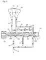
- Fig. 5 shows a schematic of an alternative phaser at null position.
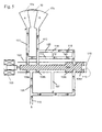
- Fig. 6 shows a schematic of an alternative phaser at full open advance.
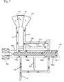
- Fig. 7 shows a schematic of an alternative phaser at full open retard.
-
- In a variable cam timing (VCT) system, the timing gear or sprocket on the camshaft is replaced by a variable angle coupling known as a "phaser", having a rotor connected to the camshaft and a housing connected to (or forming) the timing gear, which allows the camshaft to rotate independently of the timing gear, within angular limits, to change the relative timing of the camshaft and crankshaft. The term "phaser", as used here, includes the housing and the rotor, and all of the parts to control the relative angular position of the housing and rotor, to allow the timing of the camshaft to be offset from the crankshaft. In the multiple-camshaft engine, it will be understood that there could be one phaser on each camshaft, as is known to the art.
- In oil pressure actuated (OPA) or torsion assist or torque actuated (TA) phasers, the engine oil pressure is applied to one side of the vane or the other, in the retard or advance chamber, to move the vane. In TA phasers a check valve is added, either in supply lines to the chambers, or in the engine oil supply line to the spool valve. The check valve blocks oil pressure pulses due to torque reversals from propagating back into the oil system, and stop the vane from moving backward due to torque reversals. Motion of the vane due to forward torque effects is permitted.
- As shown in the figures of the present invention, the spool (104) of the spool valve (109) is located within the rotor. Passageways (111) and (113) lead oil from the spool valve (109) to the chambers (17a)(17b). Since the spool valve (109), is in the rotor and not the camshaft, the camshaft is much easier to manufacture. Externally mounted valves and elaborate passages do not need to be machined into the camshaft, since fluid only needs to travel through the phaser into the spool valve (109) which is in the rotor. Therefore, having the spool valve (109) in the rotor reduces leakage and improves the response of the phaser. Alternatively, the spool valve may be located in the housing. Note that the spool valve represented in Figures 1, 2, and 5 are different.
- Figures 1 and 2 shows the null position of a torsion assist (TA) phaser. The phaser operating fluid or hydraulic fluid (122), illustratively in the form of engine lubricating oil, flows into chambers (17a) (labeled "A" for "advance") and (17b) (labeled "R" for "retard"). Oil is introduced into the phaser by way of a common inlet line (110) through the inlet check valve (130). The spool valve (109) is made up of a spool (104) and a cylindrical member (115). The spool (104) is slidable back and forth and includes spool lands (104a) and (104b), as shown in Figure 1, and (104c) and (104d) as shown in Figure 2, which fit snugly in cylindrical member (115). As shown in the figures, supply oil is moved through cylindrical member (115) between spool lands (104a) and (104b). Supply oil is moved to passages (112) and (114), possibly through the unswitchable area of the cylindrical member (115), as shown in Figure 2 or through the area of land (104a) as shown in Figure 1.
- To maintain a phase angle, the spool (104) is positioned at null, as shown in Figures 1 and 2. When the spool (104) is in the null position, spool lands (104a) and (104b) overlap and block both of the inlet lines (111) and (113). However, there is inevitably leakage from the chambers (17a) and (17b). Makeup fluid is supplied via lines (112) and (114), connected to inlet lines (111) and (113) respectively. Within the intermediary lines (112) and (114) are check valves (118) and (120) along with restrictors (117) and (126). The restrictors (117) and (126) in the intermediary lines (112) and (114) allow continuous makeup fluid to flow into the phaser through the inlet check valves (118) and (120) and limit the loss of fluid when the spool valve is moved off the null position exposing either
line 112 orline 114 to an exhaust port. The check valves (118) and (120) block the flow of hydraulic fluid (122) out of the chambers (17a) and (17b) and the inlet lines (111) and (113) to the supply (110). The check valves (118) and (120) allow the flow of hydraulic fluid in for makeup oil, keeping the chambers full of oil, preventing back drive motion and positional oscillation. - Figure 3 shows the TA phaser in the full open advance position. Oil is introduced into the phaser by way of common inlet line (110) and check valve (130). When the spool valve (104) is moved to the left (as shown in the figure), the two lands (104a) and (104b) are not blocking either of the inlet lines (111) and (113). The oil flows unrestricted from the spool valve into inlet line (111), which leads to chamber (17a) (labeled "A" for "advance"). During cam torque reversals the check valve (130) blocks flow of oil out of line (111) to supply line (110). The oil flowing into line (111) moves the vane (16) in the direction of the arrow causing the oil present in the retard chamber (17b) (labeled "R" for "retard") to exit the chamber through inlet line (113), and exit the phaser through exhaust port (107). When spool land (104b) opens line (113) to exhaust port (107) it also opens line (114) to exhaust port (107), which allows source oil to flow from line (110) through line (114) out the exhaust port (107). Restrictor (126) in line (114) limits the amount of oil that will flow directly from line (114) out the exhaust port (107). Under certain conditions, the pressure in line (113) and line (114) will be great enough to close check valve (118) and prevent oil from flowing through line (114) out the exhaust port (107). Under all other conditions the restrictor (126) will limit the amount of oil that can flow from line (114) out the exhaust port (107).
- Figure 4 shows the TA phaser in the full open retard position. Oil is introduced into the phaser by way of common inlet line (110) and check valve (130). Moving the spool valve (104) to the right (as shown in the figure) causes the two lands (104a) and (104b) to open flow passages (111) and (113). The oil flows unrestricted from the spool valve into inlet line (113), which leads to chamber (17b) (labeled "r" for "retard"). During cam torque reversals the check valve (130) blocks flow of oil out of line (113) to supply line (110). The oil flowing into line (113) moves the vane (16) in the direction of the arrow causing the oil present in the advance chamber (17a) (labeled "a" for " advance") to exit the chamber through line (111) and exit the phaser in front of spool (109). When spool land (104a) opens line (111) to exhaust out the front of the spool (109) it also opens line (112) to exhaust, which allows source oil to flow from line (110) through line (112) out the exhaust. Restrictor (117) in line (112) limits the amount of oil that will flow directly from line (112) out the exhaust.
- In an alternate embodiment, shown in Figure 5, a torsion assist (TA) phaser is in the null position. The phaser operating fluid or hydraulic fluid (122), illustratively in the form of engine lubricating oil, flows into chambers (17a) (labeled "A" for "advance") and (17b) (labeled "R" for "retard"). Oil is introduced into the phaser by way of a common inlet line (110) and check valve (130). The spool valve (109) is made up of a spool (104) and a cylindrical member (115). The spool (104) is slidable back and forth and includes spool lands (104a), (104b), (104c), and (104d) as shown in Figure 5, which fit snugly in cylindrical member (115). As shown in the figure, supply oil is moved through cylindrical member (115) between spool lands (104a) and (104b). Supply oil is moved to passages (112) and (114), through an area of the cylindrical member (115) that is varied by the spool (104) of the spool valve (109).
- To maintain a phase angle, the spool (104) is positioned at null, as shown in Figure 5. When the spool (104) is in the null position, spool lands (104a) and (104b) overlap and block both of the inlet lines (111) and (113). However, there is inevitably leakage from the chambers (17a) and (17b). Makeup fluid is supplied via lines (112) and (114), connected to inlet lines (111) and (113) respectively. Within the intermediary lines (112) and (114) are check valves (118) and (120) along with restrictors (117) and (126). The restrictors (117) and (126) in the intermediary lines (112) and (114) allow continuous makeup fluid to flow into the phaser through the inlet check valves (118) and (120) and limit the loss of fluid when the spool valve is moved off of null position. The check valves (118) and (120) block the flow of hydraulic fluid (122) out of the chambers (17a) and (17b) and the inlet lines (111) and (113) to the supply (110). The check valves (118) and (120) allow the flow of hydraulic fluid in for makeup oil, keeping the chambers full of oil, preventing back drive motion and positional oscillation.
- Figure 6 shows the alternate TA phaser in the full open advance position. Oil is introduced into the phaser by way of common inlet line (110) and check valve (130). When the spool (104) is moved to the left (as shown in the figure) the two lands (104a), (104b) are not blocking either of the inlet lines (111) and (113). The oil flows unrestricted from the spool valve into inlet line (111), which leads to chamber (17a) (labeled "A" for "advance"). During cam torque reversals the check valve (130) blocks flow of oil out of line (111) to supply line (110). The oil flowing into line (111) moves the vane (16) in the direction of the arrow causing the oil present in the retard chamber (17b) (labeled "R" for "retard") to exit the chamber through inlet line (113), and exit the phaser through exhaust port (107). Unlike the previous embodiment, no additional fluid is supplied to inlet line (113) as both intermediary lines (112) and (114) are blocked by spool land (104d). Therefore source oil (122) does not flow from line (110) through line (114) and out the exhaust port (107). If the restriction from
spool land 104d is sufficient then restrictor 126 would not be necessary and could be removed from line (114). - Figure 7 shows the alternate TA phaser in a full open retard position. Oil is introduced into the phaser by way of common inlet line (110) and check valve (130). When the spool valve (104) is moved to the right (as shown in the figure) the two lands (104a) and (104b) are not blocking either of the inlet line (111) and (113). The oil flows unrestricted from the spool valve into inlet line (113), which leads to chamber (17b) (labeled "R" for "retard"). During cam torque reversals the check valve (130) blocks flow of oil out of line (113) to supply line (110). The oil moves the vane (16) in the direction of the arrow causing the oil present in the advance chamber (17a) (labeled "A" for "advance) to exit the chamber through inlet line (111) and exit the phaser out the front of the spool valve (109). Unlike in the previous embodiment, no additional fluid is supplied to inlet line (111) from intermediary line (112), as the intermediary lines (112) and (114) are blocked by the spool land (104c). Therefore source oil (122) does not flow from line (110) through line (112) and out the exhaust in front of the spool. If the restriction from
spool land 104c is sufficient then restrictor 117 would not be necessary and could be removed from line (112). - This invention is equally applicable to oil pressure actuated (OPA) type phasers as well as Torsion Assist (TA) style phasers. The OPA schematics could be created by simply removing
check valve 130 from figures 1-7. - Accordingly, it is to be understood that the embodiments of the invention herein described are merely illustrative of the application of the principles of the invention. Reference herein to details of the illustrated embodiments is not intended to limit the scope of the claims, which themselves recite those features regarded as essential to the invention.
Claims (11)
- A phaser for limiting leakage across a plurality of chambers for an internal combustion engine having at least one camshaft comprising:a housing having an outer circumference for accepting drive force;a rotor for connection to a camshaft coaxially located within the housing;the housing and the rotor defining at least one vane separating the plurality of chambers, the vane being capable of rotation to shift the relative angular position of the housing and the rotor,a spool valve comprising a spool having a plurality of lands slidably mounted within in a bore in the rotor, the spool slidable to route operating fluid from a supply of pressurized fluid to the chambers; andat least one passage from the supply to the chambers for providing makeup fluid, wherein the passage contains a check valve and a restrictor.
- The phaser of claim 1, wherein when the housing and the rotor are fixed relative to each other they maintain a phase angle; and
a least two of the plurality of lands prevent flow of operating fluid from the supply to the chambers when the housing and rotor are fixed relative to each other - The phaser of claim 1 or 2, wherein each of the chambers has a separate passage for providing makeup oil.
- The phaser of claim 3, wherein the separate passages to each chamber have a check valve and a restrictor.
- The phaser of claim 4, wherein the check valve and the restrictor only allow operating fluid into the plurality of chambers.
- The phaser of claim 4 or 5, wherein the restrictor restricts the loss of operating fluid from the phaser when a phase angle is no longer maintained.
- The phaser of any one of claims 1 to 6, wherein makeup fluid is routable through an unswitchable portion of the bore.
- The phaser of any one of claims 1 to 6, wherein makeup fluid is routable through a switchable portion of the bore.
- The phaser of any one of claims 1 to 8, wherein the phaser is oil pressure actuated.
- The phaser of any one of claims 1 to 9, wherein the phaser is of the torsion assist type.
- The phaser of any one of claims 1 to 10, wherein when the spool is in a null position, the spool limits leakage from chamber to chamber such that oscillation of the phaser is limited.
Applications Claiming Priority (2)
| Application Number | Priority Date | Filing Date | Title |
|---|---|---|---|
| US38898502P | 2002-06-14 | 2002-06-14 | |
| US388985P | 2002-06-14 |
Publications (1)
| Publication Number | Publication Date |
|---|---|
| EP1371819A2 true EP1371819A2 (en) | 2003-12-17 |
Family
ID=29584641
Family Applications (1)
| Application Number | Title | Priority Date | Filing Date |
|---|---|---|---|
| EP03253790A Withdrawn EP1371819A2 (en) | 2002-06-14 | 2003-06-16 | Method to reduce rotational oscillation of a vane style phaser with a center mounted spool valve |
Country Status (5)
| Country | Link |
|---|---|
| US (1) | US6779501B2 (en) |
| EP (1) | EP1371819A2 (en) |
| JP (1) | JP2004019664A (en) |
| KR (1) | KR20030096091A (en) |
| CN (1) | CN1500973A (en) |
Cited By (3)
| Publication number | Priority date | Publication date | Assignee | Title |
|---|---|---|---|---|
| WO2007126438A3 (en) * | 2005-11-23 | 2008-04-17 | Borgwarner Inc | Cta phaser with proportional oil pressure for actuation at engine condition with low cam torsionals |
| WO2010015474A1 (en) * | 2008-08-07 | 2010-02-11 | Schaeffler Kg | Camshaft adjustment device for an internal combustion engine |
| DE102013212942C5 (en) * | 2013-07-03 | 2021-04-22 | Schaeffler Technologies AG & Co. KG | Fluid supply, such as an oil supply, for a central valve system for a dry belt drive |
Families Citing this family (7)
| Publication number | Priority date | Publication date | Assignee | Title |
|---|---|---|---|---|
| DE102004024690A1 (en) * | 2004-05-19 | 2005-12-15 | Daimlerchrysler Ag | Adjusting device for a camshaft of an internal combustion engine |
| DE102005013402A1 (en) * | 2004-06-03 | 2005-12-22 | Ina-Schaeffler Kg | Device for changing timing of internal combustion engine, has driven element supported on bearing journal, driven by driving wheel through hydraulic actuator |
| EP2077312A1 (en) | 2007-12-17 | 2009-07-08 | Nippon Oil Corporation | Fuels for homogeneous charge compression ignition combustion engine |
| US8881699B2 (en) * | 2013-02-07 | 2014-11-11 | Ford Global Technologies, Llc | Feed forward dynamic spool valve |
| US9366161B2 (en) * | 2013-02-14 | 2016-06-14 | Hilite Germany Gmbh | Hydraulic valve for an internal combustion engine |
| JP6295720B2 (en) * | 2014-02-27 | 2018-03-20 | アイシン精機株式会社 | Valve timing control device |
| JP6497430B2 (en) * | 2017-11-30 | 2019-04-10 | アイシン精機株式会社 | Valve timing control device |
Family Cites Families (9)
| Publication number | Priority date | Publication date | Assignee | Title |
|---|---|---|---|---|
| US5107804A (en) | 1989-10-16 | 1992-04-28 | Borg-Warner Automotive Transmission & Engine Components Corporation | Variable camshaft timing for internal combustion engine |
| US5172659A (en) | 1989-10-16 | 1992-12-22 | Borg-Warner Automotive Transmission & Engine Components Corporation | Differential pressure control system for variable camshaft timing system |
| US5002023A (en) | 1989-10-16 | 1991-03-26 | Borg-Warner Automotive, Inc. | Variable camshaft timing for internal combustion engine |
| US5361735A (en) | 1989-10-16 | 1994-11-08 | Borg-Warner Automotive Transmission & Engine Components Corporation | Belt driven variable camshaft timing system |
| US5184578A (en) | 1992-03-05 | 1993-02-09 | Borg-Warner Automotive Transmission & Engine Components Corporation | VCT system having robust closed loop control employing dual loop approach having hydraulic pilot stage with a PWM solenoid |
| US5497738A (en) | 1992-09-03 | 1996-03-12 | Borg-Warner Automotive, Inc. | VCT control with a direct electromechanical actuator |
| JP3666072B2 (en) * | 1995-09-13 | 2005-06-29 | アイシン精機株式会社 | Switching valve |
| US6250265B1 (en) | 1999-06-30 | 2001-06-26 | Borgwarner Inc. | Variable valve timing with actuator locking for internal combustion engine |
| JP4203703B2 (en) * | 2000-06-14 | 2009-01-07 | アイシン精機株式会社 | Valve timing control device |
-
2003
- 2003-06-12 US US10/461,539 patent/US6779501B2/en not_active Expired - Fee Related
- 2003-06-14 KR KR10-2003-0038475A patent/KR20030096091A/en not_active Withdrawn
- 2003-06-14 CN CNA031524680A patent/CN1500973A/en active Pending
- 2003-06-16 EP EP03253790A patent/EP1371819A2/en not_active Withdrawn
- 2003-06-16 JP JP2003171288A patent/JP2004019664A/en not_active Abandoned
Cited By (4)
| Publication number | Priority date | Publication date | Assignee | Title |
|---|---|---|---|---|
| WO2007126438A3 (en) * | 2005-11-23 | 2008-04-17 | Borgwarner Inc | Cta phaser with proportional oil pressure for actuation at engine condition with low cam torsionals |
| WO2010015474A1 (en) * | 2008-08-07 | 2010-02-11 | Schaeffler Kg | Camshaft adjustment device for an internal combustion engine |
| US8590498B2 (en) | 2008-08-07 | 2013-11-26 | Schaeffler Technologies AG & Co. KG | Camshaft adjustment device for an internal combustion engine |
| DE102013212942C5 (en) * | 2013-07-03 | 2021-04-22 | Schaeffler Technologies AG & Co. KG | Fluid supply, such as an oil supply, for a central valve system for a dry belt drive |
Also Published As
| Publication number | Publication date |
|---|---|
| US20030230269A1 (en) | 2003-12-18 |
| US6779501B2 (en) | 2004-08-24 |
| KR20030096091A (en) | 2003-12-24 |
| CN1500973A (en) | 2004-06-02 |
| JP2004019664A (en) | 2004-01-22 |
Similar Documents
| Publication | Publication Date | Title |
|---|---|---|
| KR101084960B1 (en) | Citipager with proportional oil pressure for operating in low engine conditions with cam torsion | |
| EP1284340B1 (en) | Hybrid multi-position cam indexer having controls located in rotor | |
| EP1286023B1 (en) | Cam phaser for a four cylinder engine | |
| US8584634B2 (en) | Phaser built into a camshaft or concentric camshafts | |
| KR101190523B1 (en) | Spool Valve Controlled VCT Locking Pin Release Mechanism | |
| EP1447529B1 (en) | Phaser with a single recirculation check valve and inlet valve | |
| US7444968B2 (en) | Variable phase drive coupling | |
| EP1672184B1 (en) | Variable camshaft timing control valve with lock pin control | |
| US5353755A (en) | Arrangement of variable valve timing control system on V-type engine | |
| JP2017048793A (en) | Multi-mode variable cam timing phasor | |
| JPH07139319A (en) | Valve-timing adjusting device | |
| US7318401B2 (en) | Variable chamber volume phaser | |
| EP1371818A2 (en) | Locking pin for vane type camshaft phaser | |
| US6668778B1 (en) | Using differential pressure control system for VCT lock | |
| US6779501B2 (en) | Method to reduce rotational oscillation of a vane style phaser with a center mounted spool valve | |
| US7699031B2 (en) | Timing phaser with offset spool valve | |
| WO2006127348A1 (en) | Check valve to reduce the volume of an oil chamber | |
| EP1531240A1 (en) | Lock pin with centrifugally operated release valve | |
| US6971354B1 (en) | Variable camshaft timing system with remotely located control system |
Legal Events
| Date | Code | Title | Description |
|---|---|---|---|
| PUAI | Public reference made under article 153(3) epc to a published international application that has entered the european phase |
Free format text: ORIGINAL CODE: 0009012 |
|
| AK | Designated contracting states |
Kind code of ref document: A2 Designated state(s): AT BE BG CH CY CZ DE DK EE ES FI FR GB GR HU IE IT LI LU MC NL PT RO SE SI SK TR |
|
| AX | Request for extension of the european patent |
Extension state: AL LT LV MK |
|
| RAP1 | Party data changed (applicant data changed or rights of an application transferred) |
Owner name: BORGWARNER INC. |
|
| STAA | Information on the status of an ep patent application or granted ep patent |
Free format text: STATUS: THE APPLICATION HAS BEEN WITHDRAWN |
|
| 18W | Application withdrawn |
Effective date: 20070125 |