EP1371511A1 - A Method and System for a vehicle weatherstrip - Google Patents
A Method and System for a vehicle weatherstrip Download PDFInfo
- Publication number
- EP1371511A1 EP1371511A1 EP03101614A EP03101614A EP1371511A1 EP 1371511 A1 EP1371511 A1 EP 1371511A1 EP 03101614 A EP03101614 A EP 03101614A EP 03101614 A EP03101614 A EP 03101614A EP 1371511 A1 EP1371511 A1 EP 1371511A1
- Authority
- EP
- European Patent Office
- Prior art keywords
- flexible carrier
- closure panel
- weather strip
- disclosing agent
- agent
- Prior art date
- Legal status (The legal status is an assumption and is not a legal conclusion. Google has not performed a legal analysis and makes no representation as to the accuracy of the status listed.)
- Granted
Links
- 238000000034 method Methods 0.000 title claims abstract description 27
- 239000003795 chemical substances by application Substances 0.000 claims abstract description 63
- 239000000969 carrier Substances 0.000 claims abstract description 19
- 230000013011 mating Effects 0.000 claims description 22
- 239000000853 adhesive Substances 0.000 claims description 7
- 230000001070 adhesive effect Effects 0.000 claims description 7
- 239000011248 coating agent Substances 0.000 claims description 7
- 238000000576 coating method Methods 0.000 claims description 7
- 238000007789 sealing Methods 0.000 claims description 7
- 239000007921 spray Substances 0.000 claims description 6
- 239000000843 powder Substances 0.000 claims description 5
- 238000012546 transfer Methods 0.000 claims description 5
- 239000004820 Pressure-sensitive adhesive Substances 0.000 claims description 2
- 230000003993 interaction Effects 0.000 claims description 2
- 230000007246 mechanism Effects 0.000 claims description 2
- 238000012360 testing method Methods 0.000 description 10
- 230000008901 benefit Effects 0.000 description 7
- 238000005259 measurement Methods 0.000 description 6
- 239000000463 material Substances 0.000 description 2
- 238000004806 packaging method and process Methods 0.000 description 2
- 239000004033 plastic Substances 0.000 description 2
- 229920003023 plastic Polymers 0.000 description 2
- 238000002360 preparation method Methods 0.000 description 2
- 239000003566 sealing material Substances 0.000 description 2
- 238000005507 spraying Methods 0.000 description 2
- 239000010409 thin film Substances 0.000 description 2
- XLYOFNOQVPJJNP-UHFFFAOYSA-N water Substances O XLYOFNOQVPJJNP-UHFFFAOYSA-N 0.000 description 2
- PEDCQBHIVMGVHV-UHFFFAOYSA-N Glycerine Chemical compound OCC(O)CO PEDCQBHIVMGVHV-UHFFFAOYSA-N 0.000 description 1
- 239000004743 Polypropylene Substances 0.000 description 1
- 230000006978 adaptation Effects 0.000 description 1
- 239000000443 aerosol Substances 0.000 description 1
- 230000004075 alteration Effects 0.000 description 1
- 238000010276 construction Methods 0.000 description 1
- 239000010408 film Substances 0.000 description 1
- 238000009434 installation Methods 0.000 description 1
- 238000012986 modification Methods 0.000 description 1
- 230000004048 modification Effects 0.000 description 1
- -1 polypropylene Polymers 0.000 description 1
- 229920001155 polypropylene Polymers 0.000 description 1
- 230000009467 reduction Effects 0.000 description 1
- 239000002689 soil Substances 0.000 description 1
- 239000007787 solid Substances 0.000 description 1
- 229920003051 synthetic elastomer Polymers 0.000 description 1
- 239000005061 synthetic rubber Substances 0.000 description 1
- 238000012549 training Methods 0.000 description 1
- 230000000007 visual effect Effects 0.000 description 1
Images


Classifications
-
- B—PERFORMING OPERATIONS; TRANSPORTING
- B60—VEHICLES IN GENERAL
- B60J—WINDOWS, WINDSCREENS, NON-FIXED ROOFS, DOORS, OR SIMILAR DEVICES FOR VEHICLES; REMOVABLE EXTERNAL PROTECTIVE COVERINGS SPECIALLY ADAPTED FOR VEHICLES
- B60J10/00—Sealing arrangements
-
- B—PERFORMING OPERATIONS; TRANSPORTING
- B60—VEHICLES IN GENERAL
- B60J—WINDOWS, WINDSCREENS, NON-FIXED ROOFS, DOORS, OR SIMILAR DEVICES FOR VEHICLES; REMOVABLE EXTERNAL PROTECTIVE COVERINGS SPECIALLY ADAPTED FOR VEHICLES
- B60J10/00—Sealing arrangements
- B60J10/45—Assembling sealing arrangements with vehicle parts
-
- B—PERFORMING OPERATIONS; TRANSPORTING
- B60—VEHICLES IN GENERAL
- B60J—WINDOWS, WINDSCREENS, NON-FIXED ROOFS, DOORS, OR SIMILAR DEVICES FOR VEHICLES; REMOVABLE EXTERNAL PROTECTIVE COVERINGS SPECIALLY ADAPTED FOR VEHICLES
- B60J10/00—Sealing arrangements
- B60J10/80—Sealing arrangements specially adapted for opening panels, e.g. doors
-
- Y—GENERAL TAGGING OF NEW TECHNOLOGICAL DEVELOPMENTS; GENERAL TAGGING OF CROSS-SECTIONAL TECHNOLOGIES SPANNING OVER SEVERAL SECTIONS OF THE IPC; TECHNICAL SUBJECTS COVERED BY FORMER USPC CROSS-REFERENCE ART COLLECTIONS [XRACs] AND DIGESTS
- Y10—TECHNICAL SUBJECTS COVERED BY FORMER USPC
- Y10T—TECHNICAL SUBJECTS COVERED BY FORMER US CLASSIFICATION
- Y10T428/00—Stock material or miscellaneous articles
- Y10T428/24—Structurally defined web or sheet [e.g., overall dimension, etc.]
- Y10T428/24777—Edge feature
- Y10T428/24793—Comprising discontinuous or differential impregnation or bond
-
- Y—GENERAL TAGGING OF NEW TECHNOLOGICAL DEVELOPMENTS; GENERAL TAGGING OF CROSS-SECTIONAL TECHNOLOGIES SPANNING OVER SEVERAL SECTIONS OF THE IPC; TECHNICAL SUBJECTS COVERED BY FORMER USPC CROSS-REFERENCE ART COLLECTIONS [XRACs] AND DIGESTS
- Y10—TECHNICAL SUBJECTS COVERED BY FORMER USPC
- Y10T—TECHNICAL SUBJECTS COVERED BY FORMER US CLASSIFICATION
- Y10T428/00—Stock material or miscellaneous articles
- Y10T428/28—Web or sheet containing structurally defined element or component and having an adhesive outermost layer
-
- Y—GENERAL TAGGING OF NEW TECHNOLOGICAL DEVELOPMENTS; GENERAL TAGGING OF CROSS-SECTIONAL TECHNOLOGIES SPANNING OVER SEVERAL SECTIONS OF THE IPC; TECHNICAL SUBJECTS COVERED BY FORMER USPC CROSS-REFERENCE ART COLLECTIONS [XRACs] AND DIGESTS
- Y10—TECHNICAL SUBJECTS COVERED BY FORMER USPC
- Y10T—TECHNICAL SUBJECTS COVERED BY FORMER US CLASSIFICATION
- Y10T428/00—Stock material or miscellaneous articles
- Y10T428/28—Web or sheet containing structurally defined element or component and having an adhesive outermost layer
- Y10T428/2848—Three or more layers
Definitions
- the present invention relates to a method and system for determining interference fit of a weather strip interposed between movable and immovable closure panels of vehicle so as to enable adjustments intended to minimize air and water leaks between the panels and their corresponding mating surfaces.
- FIGURE 1 is a stylized representation of a body structure, 10, having movable closure panels 12 and first plurality of weather strip seals 14 and a second plurality of weather strip seals 16.
- Weather strips 14 of FIGURE 1 leak because closure panel 12 does not compress seal 14 sufficiently so as to prevent a leakage path between body 10 and seal 14.
- closure panel 13 compresses seal 16 sufficiently to create an interference fit between seal 16 and body 10. As a result, no aspiration leak will exist between closure panel 13 and body 10, or more precisely, between seal 16 and body 10.
- the chalk test This involves spraying chalk from an aerosol can onto a vehicle weather strip. Then the door is closed and opened and presence of transferred chalk is noted.
- the chalk test is unreliable because the amount of chalk transferred from the weather strip to the door depends to a very great extent on the normal force developed between the weather strip and the vehicle body or door. Also, the sprayed chalk flies everywhere and is extremely difficult to remove from the vehicle. This type of test is therefore not appropriate for customer vehicles or vehicles being produced in assembly plants.
- a second type of prior art test involves a thin film which when trapped between the weather strip and the closure panel changes color in relation to the pressure being applied.
- Unfortunately, such films do not work at the low normal pressures generally needed to properly engineer and provide automotive weather strips.
- electronic pressure measuring devices such as thin film tactile pressure sensors may be used to determine the normal force between a weather strip and a vehicle closure panel or body.
- electronic pressure measuring devices such as thin film tactile pressure sensors may be used to determine the normal force between a weather strip and a vehicle closure panel or body.
- weather strips Other type of tests for weather strips include air leakage testing which, although allowing measurement of the gross amount of air escaping from a passenger cabin, cannot pinpoint the location of an air leak.
- ultrasonic testing may be used to prevent severe weather strip leaking from occurring, it is very difficult to relate the ultrasonic result to the severity of the weather strip gaps, if any.
- sealing gaps are often measured in a vehicle body before the installation of weather strips. However, such gaps do not typically correlate well with the weather strip gaps experienced on vehicles. This lack of correlation may arise from the inability to precisely predict the free standing height and characteristic of seals.
- Electronic sound measurement devices are also used to analyze wind noise. However, such devices cannot locate the source of the wind noise with the precision needed to adjust the seal interference to achieve a desired reduction wind noise.
- a method for determining the fit of a weather strip for sealing a closure panel of a vehicle characterised in that the method comprises attaching at least one flexible carrier, having a transferable disclosing agent disposed thereupon, to a portion of said closure panel which normally contacts the weather strip whenever the closure panel is in a closed position, closing the closure panel to allow removal of a portion of the disclosing agent from the carrier and reading the pattern of the disclosure agent removed from the flexible carrier due to the interaction of the closure panel and the flexible carrier with the weather strip, so as to identify whether an interference fit is present between the weather strip and the closure panel.
- the weather strip may be positioned between a closure panel and a body comprising a portion of the vehicle.
- a plurality of flexible carriers having disclosing agent disposed thereon may be applied to the closure panel.
- the weather strip may be positioned between a closure panel and a body comprising a portion of the vehicle and there may be a plurality of flexible carriers having disclosing agent disposed thereon applied to the closure panel, wherein attaching at least one flexible carrier comprises attaching the plurality of flexible carriers, each having a transferable disclosing agent disposed thereupon, to a portion of said closure panel which normally contacts the weather strip when the closure panel is closed, closing the closure panel comprises moving the closure panel to a position in which the weather strip is confined between the closure panel and the body of the vehicle, so as to permit transfer of the disclosing agent from the flexible carrier to the weather strip at any location where the closure panel and flexible carrier are in contact with the weather strip with a normal force exceeding a predetermined threshold and reading the pattern of the disclosure agent removed comprises reading the pattern of the disclosing agent transferred from the flexible carriers to the weather strip so as to identify whether an interference fit is present between the weather strip and the closure panel.
- the method may further comprise the step of opening the closure panel before reading the pattern.
- Said disclosing agent may be a pressure sensitive coating.
- Said disclosing agent is a powder which is deposited onto the flexible carrier.
- the powder may be a frangible powder which is deposited onto said flexible carrier.
- said disclosing agent may be a fragile coating which is deposited onto said flexible carrier.
- the disclosing agent may be deposited by being sprayed onto the flexible carrier.
- the flexible carrier may be a tape securable to the closure panel by adhesive.
- the flexible carrier may be a tape having an adhesive backing.
- the disclosing agent may be transferred from the flexible carriers to the weather strip.
- the closure panel may be a passenger door or may be a vision unit such as a windshield.
- a system for determining the fit between a closure panel and a weather strip attached to a body of a vehicle characterised in that the system comprises a flexible carrier, a disclosing agent disposed upon a first surface of the flexible carrier and an attachment agent, disposed upon a second surface of the flexible carrier, thereby permitting the flexible carrier to be removably positioned between a portion of said weather strip and a portion of the closure panel which are normally in contact when the closure panel is in a closed position, so as to allow a portion of the disclosing agent to be displaced from the flexible carrier when the closure panel is contacted by the weather strip.
- the disclosing agent which is displaced from the flexible carrier may be transferred from the flexible carrier to a portion of the weather strip which is in contact with the closure panel when the closure panel is in a closed position.
- an interference tape for determining the fit between first and second machine parts having a first mating surface integral with said first machine part and a second mating surface integral with said second machine part characterised in that the interference tape comprises a flexible carrier, a disclosing agent disposed upon a first surface of the flexible carrier and an attachment agent disposed upon a second surface of the flexible carrier to permit the flexible carrier to be removably positioned upon the first mating surface so that, when the first mating surface is brought into contact with a portion of the second mating surface, a portion of the disclosing agent is removed from the flexible carrier and transferred to the second mating surface.
- an apparatus for preparing an interference indicating tape in accordance with said third aspect of the invention characterised in that the apparatus comprises a roll of flexible carrier stock having a first surface coated with a pressure-sensitive adhesive, a spray nozzle and supply mechanism for furnishing disclosing agent to the spray nozzle and a feeder for drawing the flexible carrier stock from the roll past the spray nozzle, so as to permit the nozzle to deposit disclosing agent upon a second surface of the flexible carrier.
- the apparatus may further comprise a package for holding a plurality of flexible carriers bearing disclosing agent in a plastic container with a manually removable lid.
- weather strip is intended to mean a class of resilient sealing materials commonly used, for example, in automotive bodies. Such sealing materials may have tubular, or flat or flanged, or solid trapezoidal shapes, and dozens of other shapes as well.
- the present invention offers a method and system for determining whether such seals adequately contact the closure panels and body openings to which they are applied.
- FIGURE 2 illustrates a number of flexible carriers 18 which are yet to be cut into individual interference indicator tape (IIT) strips shown in FIGURE 3.
- IIT interference indicator tape
- the system includes tape 20 having an adhesive backing 23.
- the adhesive backing 23 allows flexible carrier 18 to be adhered to a closure panel or weather strip.
- a transferable disclosing agent 22 is applied to the non-sticking side of tape 20.
- the disclosing agent preferably comprises a fragile coating which is sprayed onto flexible carrier 18 or another frangible coating which is deposited onto the flexible carrier 18.
- Magnaflux® Spotchek® SKD-S2® developer powder provides a useful disclosing agent for practicing the present invention at an installed depth of 0.05-0.15 mm.
- 3M® Scotch Brand® sealing tape stock no. 3750-P, in a 2" width, comprising polypropylene having a thickness of about 0.1 mm and a synthetic rubber adhesive is also appropriate for practicing the present invention.
- a nonstick backing 26 is applied to the sticky or adhesive side of tape 20 during preparation of flexible carrier, so as to provide temporary stiffening of tape 20. Paper tabs 24 are also adhered to the sticky or bottom side of tape 20, to permit easier handling of tape 20.
- the disclosing agent readily transfer from the flexible carrier to the mating surface when the closure panel is moved into its closed position, without separating from the interference indicator tape (IIT) in advance of its intended use.
- the disclosing agent serves as a pressure sensitive coating which transfers from the carrier to the mating surface, whether it be a weather strip, or other structure, when the closure panel is moved to a closed position.
- flexible carrier 18 as prepared for use as an IIT may comprise a strip of approximately 12.5mm ( 1 ⁇ 2" ) in width and about 50 mm (2") in length. All that need be done to apply flexible carrier 18 is to remove nonstick backing 26 from tape 20. It is easily seen that the present method is economical because large amounts of materials and time are not needed to practice this invention, particularly in the preparation phase.
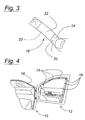
- FIGURE 4 illustrates a closure panel, in this case automotive door 12, having a plurality of IIT strips 18 attached thereto. Door 12 is then closed into contact with weather strip 16 carried on auto body 10.
- the closed door, body and weather strip are represented in FIGURE 5, wherein IIT 18 is interposed between weather strip 16 and body 10, with door 12 providing a normal force against weather strip 16 so as to cause transfer of the disclosing agent from IIT 18 to weather strip 16.
- FIGURE 4 shows an arrangement in which the weather strip or seals are attached to body 10 of a vehicle and flexible carriers 18 are attached to door 12 such that disclosing agent 22 is removed from flexible carriers 18 in the regions in which weather strip 16 contacts door 12.
- contact region 28 on IIT 18 shows the precise location of the interference between closure 12 and the facing weather strip or seal 16.
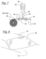
- FIGURE 8 illustrates vision unit 46 applied to body 10 of a vehicle.
- vision unit applies to either a windshield, or a backlight, or other type of glazing which is fixed in place.
- the fit of the weather strip may be assessed by applying a plurality of flexible carriers 18 to vision unit 46 and then placing vision unit down on weather strip 16, which is interposed between the vehicle body and vision unit 46. Patterns similar to that shown in FIGURE 6 will result, and the interference between weather strip 16 and vision unit 46 will be readable.
- the interference pattern illustrated in FIGURE 6 may be measured with a scale or other measuring instruments, and the measurements recorded, so as to provide an objective indication of weather strip engagement.
- FIGURE 7 illustrates an apparatus for producing a flexible carrier equipped with disclosing agent.
- material from roll 32 which includes tape 20, paper tabs 24, and nonstick backing 26, is pulled through pinch rollers 42 by drive rollers 44.
- tape 20, including tabs 24 and backing 26 is fed between pinch rollers 42 and drive rollers 44, disclosing agent 22 is sprayed upon the non-sticky side of tape 20, by means of nozzle 34, which is supplied with disclosing agent 22 by pump 36 from reservoir 38.
- nozzle 34 which is supplied with disclosing agent 22 by pump 36 from reservoir 38.
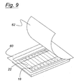
- FIGURE 9 illustrates packaging for completely assembled IIT carriers 18, including previously deposited disclosing agent 22.
- Container 60 preferably molded of plastics, has peel-off lid 62.
- Container 60 allows the unused IIT carriers to be transported without spillage, a capability which is important to field use of the present inventive system and method.
- the purpose of the present invention therefore is to provide a method and measurement system to identify and quantify correct fit of weather strips, which is achieved when there is interference between the weather strip and the panel or body surface to which it is sealing.
- the present invention provides a "interference indicator tape” (IIT) which can be used to reduce interference variability of dynamic seals such as weather strips on the doors of vehicles as well as other movable closure panels such as moon roofs and deck lid and engine compartment hoods. IIT may also be used to reduce wind and water leaks and to fit closure panels such as windshields and backlights.
- IIT interference indicator tape
- Another advantage of the present invention resides in the fact that the present system and method provides visual feedback to the user of the adequacy, or inadequacy, of a sealing system.
- the present method and system provide a repeatable and reproducible measurement procedure for quantifying interference gap between two relatively movable panels of a vehicle.
- testing as claimed in this method maybe completed in a few minutes so as to allow a great number of vehicles to be tested in a brief period of time.
- the present system does not soil a vehicle when it is employed.
- the flexible carriers may be positioned either upon a weather strip, or upon a closure panel coming in contact with the weather strip when the panel is closed.
- the present invention may be used as a system for determining the fit between first and second machine parts having a first mating surface integral with said first machine part and a second mating surface integral with said second machine part, where the flexible carrier of the IIT is removably positioned upon the first mating surface, so as to allow a portion of the disclosing agent to be removed from the flexible carrier and transferred to the second mating surface when the first mating surface is contacted with a portion of the second mating surface.
Landscapes
- Engineering & Computer Science (AREA)
- Mechanical Engineering (AREA)
- Seal Device For Vehicle (AREA)
- Automobile Manufacture Line, Endless Track Vehicle, Trailer (AREA)
Abstract
Description
- The present invention relates to a method and system for determining interference fit of a weather strip interposed between movable and immovable closure panels of vehicle so as to enable adjustments intended to minimize air and water leaks between the panels and their corresponding mating surfaces.
- Wind noise around the doors and windows of motor vehicles is a frequent source of dissatisfaction for motorists. Wind noise arises from air passing through the door and weather strip interfaces. Motion of the vehicle creates a pressure differential between the vehicle interior and exterior which increases as the vehicle reaches higher speed. This pressure differential causes a flow of air through the interfaces between the closure panels and the weather strips or seals. This leakage is generally referred to as an "aspiration leak". FIGURE 1 is a stylized representation of a body structure, 10, having
movable closure panels 12 and first plurality ofweather strip seals 14 and a second plurality ofweather strip seals 16.Weather strips 14 of FIGURE 1 leak becauseclosure panel 12 does not compressseal 14 sufficiently so as to prevent a leakage path betweenbody 10 andseal 14. On the other hand, closure panel 13 compressesseal 16 sufficiently to create an interference fit betweenseal 16 andbody 10. As a result, no aspiration leak will exist between closure panel 13 andbody 10, or more precisely, betweenseal 16 andbody 10. - Automotive designers and engineers have used a variety of tests to determine the presence and source of weather strip leaks. Once such test is called the chalk test. This involves spraying chalk from an aerosol can onto a vehicle weather strip. Then the door is closed and opened and presence of transferred chalk is noted. Unfortunately the chalk test is unreliable because the amount of chalk transferred from the weather strip to the door depends to a very great extent on the normal force developed between the weather strip and the vehicle body or door. Also, the sprayed chalk flies everywhere and is extremely difficult to remove from the vehicle. This type of test is therefore not appropriate for customer vehicles or vehicles being produced in assembly plants.
- A second type of prior art test involves a thin film which when trapped between the weather strip and the closure panel changes color in relation to the pressure being applied. Unfortunately, such films do not work at the low normal pressures generally needed to properly engineer and provide automotive weather strips.
- As might be imagined, electronic pressure measuring devices such as thin film tactile pressure sensors may be used to determine the normal force between a weather strip and a vehicle closure panel or body. Unfortunately, such systems are plagued with low resolution, very great expense, extraordinary time demands upon the human operator, and difficulties in reproducing the study results because of the need to precisely determine locations where measurements are taken.
- Other type of tests for weather strips include air leakage testing which, although allowing measurement of the gross amount of air escaping from a passenger cabin, cannot pinpoint the location of an air leak. Although ultrasonic testing may be used to prevent severe weather strip leaking from occurring, it is very difficult to relate the ultrasonic result to the severity of the weather strip gaps, if any. Finally, sealing gaps are often measured in a vehicle body before the installation of weather strips. However, such gaps do not typically correlate well with the weather strip gaps experienced on vehicles. This lack of correlation may arise from the inability to precisely predict the free standing height and characteristic of seals. Electronic sound measurement devices are also used to analyze wind noise. However, such devices cannot locate the source of the wind noise with the precision needed to adjust the seal interference to achieve a desired reduction wind noise.
- It is an object of this invention to provide an improved method for determining the fit between two parts so as to establish the likelihood of a leak therebetween.
- According to a first aspect of the invention there is provided a method for determining the fit of a weather strip for sealing a closure panel of a vehicle characterised in that the method comprises attaching at least one flexible carrier, having a transferable disclosing agent disposed thereupon, to a portion of said closure panel which normally contacts the weather strip whenever the closure panel is in a closed position, closing the closure panel to allow removal of a portion of the disclosing agent from the carrier and reading the pattern of the disclosure agent removed from the flexible carrier due to the interaction of the closure panel and the flexible carrier with the weather strip, so as to identify whether an interference fit is present between the weather strip and the closure panel.
- The weather strip may be positioned between a closure panel and a body comprising a portion of the vehicle.
- Preferably, a plurality of flexible carriers having disclosing agent disposed thereon may be applied to the closure panel.
- The weather strip may be positioned between a closure panel and a body comprising a portion of the vehicle and there may be a plurality of flexible carriers having disclosing agent disposed thereon applied to the closure panel, wherein attaching at least one flexible carrier comprises attaching the plurality of flexible carriers, each having a transferable disclosing agent disposed thereupon, to a portion of said closure panel which normally contacts the weather strip when the closure panel is closed, closing the closure panel comprises moving the closure panel to a position in which the weather strip is confined between the closure panel and the body of the vehicle, so as to permit transfer of the disclosing agent from the flexible carrier to the weather strip at any location where the closure panel and flexible carrier are in contact with the weather strip with a normal force exceeding a predetermined threshold and reading the pattern of the disclosure agent removed comprises reading the pattern of the disclosing agent transferred from the flexible carriers to the weather strip so as to identify whether an interference fit is present between the weather strip and the closure panel.
- The method may further comprise the step of opening the closure panel before reading the pattern.
- Said disclosing agent may be a pressure sensitive coating.
- Said disclosing agent is a powder which is deposited onto the flexible carrier. The powder may be a frangible powder which is deposited onto said flexible carrier.
- Alternatively, said disclosing agent may be a fragile coating which is deposited onto said flexible carrier.
- In either case, the disclosing agent may be deposited by being sprayed onto the flexible carrier.
- The flexible carrier may be a tape securable to the closure panel by adhesive.
- Preferably, the flexible carrier may be a tape having an adhesive backing.
- The disclosing agent may be transferred from the flexible carriers to the weather strip.
- The closure panel may be a passenger door or may be a vision unit such as a windshield.
- According to a second aspect of the invention there is provided a system for determining the fit between a closure panel and a weather strip attached to a body of a vehicle, characterised in that the system comprises a flexible carrier, a disclosing agent disposed upon a first surface of the flexible carrier and an attachment agent, disposed upon a second surface of the flexible carrier, thereby permitting the flexible carrier to be removably positioned between a portion of said weather strip and a portion of the closure panel which are normally in contact when the closure panel is in a closed position, so as to allow a portion of the disclosing agent to be displaced from the flexible carrier when the closure panel is contacted by the weather strip.
- The disclosing agent which is displaced from the flexible carrier may be transferred from the flexible carrier to a portion of the weather strip which is in contact with the closure panel when the closure panel is in a closed position.
- According to a third aspect of the invention there is provided an interference tape for determining the fit between first and second machine parts having a first mating surface integral with said first machine part and a second mating surface integral with said second machine part characterised in that the interference tape comprises a flexible carrier, a disclosing agent disposed upon a first surface of the flexible carrier and an attachment agent disposed upon a second surface of the flexible carrier to permit the flexible carrier to be removably positioned upon the first mating surface so that, when the first mating surface is brought into contact with a portion of the second mating surface, a portion of the disclosing agent is removed from the flexible carrier and transferred to the second mating surface.
- According to a fourth aspect of the invention there is provided an apparatus for preparing an interference indicating tape in accordance with said third aspect of the invention characterised in that the apparatus comprises a roll of flexible carrier stock having a first surface coated with a pressure-sensitive adhesive, a spray nozzle and supply mechanism for furnishing disclosing agent to the spray nozzle and a feeder for drawing the flexible carrier stock from the roll past the spray nozzle, so as to permit the nozzle to deposit disclosing agent upon a second surface of the flexible carrier.
- The apparatus may further comprise a package for holding a plurality of flexible carriers bearing disclosing agent in a plastic container with a manually removable lid.
- The invention will now be described by way of example with reference to the accompanying drawing of which:-
- FIG. 1 is a schematic representation of a weather strip seal system and closure system illustrating the source of aspiration leaks between seals and closure panels in the vehicle;
- FIG. 2 is a perspective view of an interference indicator tape as claimed in the present invention, prior to being cut into separate strips;
- FIG. 3 is a prospective view of an interference indicator tape as claimed in the present invention prepared for application to a vehicle;
- FIG. 4 illustrates a plurality of interference indicator tape units applied to a door of a vehicle;
- FIG. 5 is a schematic illustration showing the positioning of a flexible carrier between a vehicle body and a weather strip, and shows the door as closed against the weather strip so as to allow the disclosing agent to be transferred from the tape to a portion from the weather strip which is in contact with the vehicle body.
- FIG. 6 illustrates a contact region between a weather strip and the door of FIGURE 4, as indicated upon the interference indicator tape;
- FIG. 7 illustrates an apparatus for preparing a flexible carrier having a transferable disclosing agent disposed thereupon;
- FIG.8 illustrates use of a system and method according to the present invention to assess the interference fit of a weather strip with a vision unit such as a windshield or backlight; and
- FIG. 9 illustrates a packaging system for containing prepared interference indicator tape.
-
- As used herein, the term "weather strip" is intended to mean a class of resilient sealing materials commonly used, for example, in automotive bodies. Such sealing materials may have tubular, or flat or flanged, or solid trapezoidal shapes, and dozens of other shapes as well. The present invention offers a method and system for determining whether such seals adequately contact the closure panels and body openings to which they are applied.
- A system for determining the fit between a closure panel and a weather strip attached to the body of a vehicle can be prepared as a series of conjoined
flexible carriers 18 as shown in FIGURE 2. In essence, FIGURE 2 illustrates a number offlexible carriers 18 which are yet to be cut into individual interference indicator tape (IIT) strips shown in FIGURE 3. Concentrating for the moment on FIGURE 2, it is seen that the system includestape 20 having anadhesive backing 23. Theadhesive backing 23 allowsflexible carrier 18 to be adhered to a closure panel or weather strip. - A transferable disclosing
agent 22 is applied to the non-sticking side oftape 20. The disclosing agent preferably comprises a fragile coating which is sprayed ontoflexible carrier 18 or another frangible coating which is deposited onto theflexible carrier 18. - The inventors of the present invention have determined that Magnaflux® Spotchek® SKD-S2® developer powder provides a useful disclosing agent for practicing the present invention at an installed depth of 0.05-0.15 mm. Moreover, 3M® Scotch Brand® sealing tape stock no. 3750-P, in a 2" width, comprising polypropylene having a thickness of about 0.1 mm and a synthetic rubber adhesive is also appropriate for practicing the present invention.
- A
nonstick backing 26 is applied to the sticky or adhesive side oftape 20 during preparation of flexible carrier, so as to provide temporary stiffening oftape 20.Paper tabs 24 are also adhered to the sticky or bottom side oftape 20, to permit easier handling oftape 20. - Those skilled in the art will appreciate in view of this disclosure that other types of disclosing agents may be employed with a system and method as claimed in the present invention.
- A principal need in this regard is that the disclosing agent readily transfer from the flexible carrier to the mating surface when the closure panel is moved into its closed position, without separating from the interference indicator tape (IIT) in advance of its intended use. In other words, the disclosing agent serves as a pressure sensitive coating which transfers from the carrier to the mating surface, whether it be a weather strip, or other structure, when the closure panel is moved to a closed position.
- As shown in FIGURE 3,
flexible carrier 18 as prepared for use as an IIT, may comprise a strip of approximately 12.5mm ( ½" ) in width and about 50 mm (2") in length. All that need be done to applyflexible carrier 18 is to removenonstick backing 26 fromtape 20. It is easily seen that the present method is economical because large amounts of materials and time are not needed to practice this invention, particularly in the preparation phase. - FIGURE 4 illustrates a closure panel, in this case
automotive door 12, having a plurality of IIT strips 18 attached thereto.Door 12 is then closed into contact withweather strip 16 carried onauto body 10. The closed door, body and weather strip are represented in FIGURE 5, whereinIIT 18 is interposed betweenweather strip 16 andbody 10, withdoor 12 providing a normal force againstweather strip 16 so as to cause transfer of the disclosing agent fromIIT 18 toweather strip 16. - Those skilled in the art will appreciate in view of this disclosure that a system and method as claimed in the present invention could be employed with closure structures of varying types. For example, the seal or other weather strip could be applied to either a movable closure panel or to the mating surface of the body of a vehicle. Moreover, the individual IIT carriers could be applied to either the weather strip or to the panel which opposes the weather strip when the closure is made, regardless of whether the weather strip is attached to the door or the body of the vehicle. For example, FIGURE 4 shows an arrangement in which the weather strip or seals are attached to
body 10 of a vehicle andflexible carriers 18 are attached to door 12 such that disclosingagent 22 is removed fromflexible carriers 18 in the regions in whichweather strip 16contacts door 12. This result is shown in FIGURE 6 whereincontact region 28 on IIT 18 ( a region in which disclosingagent 22 has been removed from carrier portion of IIT 18) shows the precise location of the interference betweenclosure 12 and the facing weather strip orseal 16. - FIGURE 8 illustrates
vision unit 46 applied tobody 10 of a vehicle. As used herein, the term vision unit applies to either a windshield, or a backlight, or other type of glazing which is fixed in place. With the construction of FIGURE 8, the fit of the weather strip may be assessed by applying a plurality offlexible carriers 18 tovision unit 46 and then placing vision unit down onweather strip 16, which is interposed between the vehicle body andvision unit 46. Patterns similar to that shown in FIGURE 6 will result, and the interference betweenweather strip 16 andvision unit 46 will be readable. The interference pattern illustrated in FIGURE 6 may be measured with a scale or other measuring instruments, and the measurements recorded, so as to provide an objective indication of weather strip engagement. - FIGURE 7 illustrates an apparatus for producing a flexible carrier equipped with disclosing agent. Thus, material from
roll 32, which includestape 20,paper tabs 24, andnonstick backing 26, is pulled throughpinch rollers 42 bydrive rollers 44. Astape 20, includingtabs 24 andbacking 26, is fed betweenpinch rollers 42 and driverollers 44, disclosingagent 22 is sprayed upon the non-sticky side oftape 20, by means of nozzle 34, which is supplied with disclosingagent 22 bypump 36 fromreservoir 38. In this manner, completelyprepared IIT 18 maybe obtained without the need for manual spraying and with much more consistent results in terms of the disposition of disclosingagent 22 ontape 20. - FIGURE 9 illustrates packaging for completely assembled
IIT carriers 18, including previously deposited disclosingagent 22.Container 60, preferably molded of plastics, has peel-offlid 62.Container 60 allows the unused IIT carriers to be transported without spillage, a capability which is important to field use of the present inventive system and method. - The purpose of the present invention therefore is to provide a method and measurement system to identify and quantify correct fit of weather strips, which is achieved when there is interference between the weather strip and the panel or body surface to which it is sealing. In essence, the present invention provides a "interference indicator tape" (IIT) which can be used to reduce interference variability of dynamic seals such as weather strips on the doors of vehicles as well as other movable closure panels such as moon roofs and deck lid and engine compartment hoods. IIT may also be used to reduce wind and water leaks and to fit closure panels such as windshields and backlights.
- It is an advantage of the present invention that a system and method as claimed in this invention provides a straightforward system for determining the adequacy of sealing of a closure panel.
- Another advantage of the present invention resides in the fact that the present system and method provides visual feedback to the user of the adequacy, or inadequacy, of a sealing system.
- It is another advantage of the present invention that the present method and system provide a repeatable and reproducible measurement procedure for quantifying interference gap between two relatively movable panels of a vehicle.
- It is another advantage of the present invention that testing as claimed in this method maybe completed in a few minutes so as to allow a great number of vehicles to be tested in a brief period of time.
- It is another advantage of the present invention that this system may be implemented at low cost.
- It is another advantage of the present invention that the present method and system may be employed by personnel having minimal training.
- It is another advantage of the present invention that the present system does not soil a vehicle when it is employed.
- Although the present invention has been described in connection with particular embodiments thereof, it is to be understood that various modifications, alterations and adaptations may be made by those skilled in the art without departing from the scope of the invention.
- For example the flexible carriers may be positioned either upon a weather strip, or upon a closure panel coming in contact with the weather strip when the panel is closed.
- It will be further appreciated that the present invention may be used as a system for determining the fit between first and second machine parts having a first mating surface integral with said first machine part and a second mating surface integral with said second machine part, where the flexible carrier of the IIT is removably positioned upon the first mating surface, so as to allow a portion of the disclosing agent to be removed from the flexible carrier and transferred to the second mating surface when the first mating surface is contacted with a portion of the second mating surface.
Claims (10)
- A method for determining the fit of a weather strip (14, 16) for sealing a closure panel (12, 13, 46) of a vehicle characterised in that the method comprises attaching at least one flexible carrier (18) having a transferable disclosing agent (22) disposed thereupon, to a portion of said closure panel (12, 13, 46) which normally contacts the weather strip (14, 16) whenever the closure panel (12, 13, 46) is in a closed position, closing the closure panel (12, 13, 46) to allow removal of a portion of the disclosing agent (22) from the carrier (18) and reading the pattern of the disclosure agent (22) removed from the flexible carrier (18) due to the interaction of the closure panel (12, 13, 46) and the flexible carrier (18) with the weather strip (14,16), so as to identify whether an interference fit is present between the weather strip (14, 16) and the closure panel (12, 13, 46).
- A method as claimed in Claim 1 in which the weather strip (14, 16) is positioned between a closure panel (12, 13, 46) and a body (10) comprising a portion of the vehicle and there are a plurality of flexible carriers (18) having disclosing agent (22) disposed thereon applied to the closure panel (12, 13, 46), wherein attaching at least one flexible carrier comprises attaching the plurality of flexible carriers (18), each having a transferable disclosing agent (22) disposed thereupon, to a portion of said closure panel (12, 13, 46) which normally contacts the weather strip (14, 16) when the closure panel is closed, closing the closure panel (12, 13, 46) comprises moving the closure panel (12, 13, 46) to a position in which the weather strip (14, 16) is confined between the closure panel (12, 13, 46) and the body (10) of the vehicle, so as to permit transfer of the disclosing agent (22) from the flexible carrier (18) to the weather strip (14, 16) at any location where the closure panel (12, 13, 46) and flexible carrier (18) are in contact with the weather strip (14, 16) with a normal force exceeding a predetermined threshold and reading the pattern of the disclosure agent removed comprises reading the pattern of the disclosing agent (22) transferred from the flexible carriers (18) to the weather strip (14, 16) so as to identify whether an interference fit is present between the weather strip (14, 16) and the closure panel (12, 13, 46).
- A method as claimed in Claim 1 or in claim 2 wherein said disclosing agent (22) is a pressure sensitive coating.
- A method as claimed in Claim 1 or in Claim 2 wherein said disclosing agent (22) is a powder which is deposited onto the flexible carrier (18).
- A method as claimed in Claim 1 or in Claim 2 wherein said disclosing agent (22) is a fragile coating which is deposited onto said flexible carrier.
- A method as claimed in any of Claims 1 to 5 wherein the flexible carrier (18) is a tape (20) securable to the closure panel by adhesive (23).
- A system for determining the fit between a closure panel (12, 13, 46) and a weather strip ( 14, 16) attached to a body (10) of a vehicle, characterised in that the system comprises a flexible carrier (18), a disclosing agent (22) disposed upon a first surface of the flexible carrier (18) and an attachment agent (23), disposed upon a second surface of the flexible carrier (18), thereby permitting the flexible carrier (18) to be removably positioned between a portion of said weather strip (14, 16) and a portion of the closure panel (12, 13, 46) which are normally in contact when the closure panel (12, 13, 46) is in a closed position, so as to allow a portion of the disclosing agent (22) to be displaced from the flexible carrier (18) when the closure panel (12, 13, 46) is contacted by the weather strip (14, 16).
- A system as claimed in Claim 8 wherein the disclosing agent (22) which is displaced from the flexible carrier (18) is transferred from the flexible carrier (18) to a portion of the weather strip (14, 16) which is in contact with the closure panel (12, 13, 46) when the closure panel (12, 13, 46) is in a closed position.
- An interference tape for determining the fit between first and second machine parts (12, 13, 46 and 10) having a first mating surface integral with said first machine part and a second mating surface integral with said second machine part characterised in that the interference tape comprises a flexible carrier (18), a disclosing agent (22) disposed upon a first surface of the flexible carrier (18) and an attachment agent (23) disposed upon a second surface of the flexible carrier (18) to permit the flexible carrier (18) to be removably positioned upon the first mating surface so that, when the first mating surface is brought into contact with a portion of the second mating surface, a portion of the disclosing agent (22) is removed from the flexible carrier (18) and transferred to the second mating surface.
- An apparatus for preparing an interference indicating tape as claimed in Claim 9 characterised in that the apparatus comprises a roll (32) of flexible carrier stock (18) having a first surface coated with a pressure-sensitive adhesive, a spray nozzle (34) and supply mechanism (36, 38) for furnishing disclosing agent (22) to the spray nozzle (34) and a feeder (44, 42) for drawing the flexible carrier stock (20, 24) from the roll (32) past the spray nozzle (34), so as to permit the nozzle (34) to deposit disclosing agent (22) upon a second surface of the flexible carrier (18).
Applications Claiming Priority (2)
| Application Number | Priority Date | Filing Date | Title |
|---|---|---|---|
| US64130 | 1998-04-22 | ||
| US10/064,130 US6860067B2 (en) | 2002-06-13 | 2002-06-13 | Method and system for determining weather strip fit for a closure panel of a vehicle |
Publications (2)
| Publication Number | Publication Date |
|---|---|
| EP1371511A1 true EP1371511A1 (en) | 2003-12-17 |
| EP1371511B1 EP1371511B1 (en) | 2008-09-24 |
Family
ID=29581871
Family Applications (1)
| Application Number | Title | Priority Date | Filing Date |
|---|---|---|---|
| EP03101614A Expired - Lifetime EP1371511B1 (en) | 2002-06-13 | 2003-06-03 | A Method and System for a vehicle weatherstrip |
Country Status (3)
| Country | Link |
|---|---|
| US (2) | US6860067B2 (en) |
| EP (1) | EP1371511B1 (en) |
| DE (1) | DE60323708D1 (en) |
Families Citing this family (6)
| Publication number | Priority date | Publication date | Assignee | Title |
|---|---|---|---|---|
| US20120261944A1 (en) * | 2008-09-18 | 2012-10-18 | Kreil Craig J | Vehicle Seal With Sensor Feedback |
| US8888172B2 (en) * | 2012-08-02 | 2014-11-18 | Ford Global Technologies, Llc | Vehicle glazing assembly with noise and vibration reduction techniques |
| DE102013114775A1 (en) * | 2013-12-23 | 2015-06-25 | Cqlt Saargummi Technologies S.À.R.L. | Method for forming seals on vehicle bodies |
| US10428243B2 (en) * | 2016-12-06 | 2019-10-01 | Ford Motor Company | Method of utilizing thin film pressure sensitive strips to measure pressure applied to a seal |
| ES2748871T3 (en) * | 2017-03-23 | 2020-03-18 | Elkamet Kunststofftechnik Gmbh | Mounting device for use in a bar arrangement and procedure for realization in a bar arrangement |
| US10731978B2 (en) * | 2017-09-29 | 2020-08-04 | Ford Motor Company | Method and system for measuring seal contact |
Citations (4)
| Publication number | Priority date | Publication date | Assignee | Title |
|---|---|---|---|---|
| US5046285A (en) * | 1990-09-17 | 1991-09-10 | General Motors Corporation | Vacuum system for deflating weatherstrips |
| US5253453A (en) * | 1990-12-12 | 1993-10-19 | Draftex Industries Limited | Sealing arrangements |
| GB2272299A (en) * | 1990-09-12 | 1994-05-11 | Draftex Ind Ltd | Testing vehicle door sealing strips. |
| EP0822109A1 (en) * | 1996-07-29 | 1998-02-04 | Draftex Industries Limited | Window sealing arrangements |
Family Cites Families (5)
| Publication number | Priority date | Publication date | Assignee | Title |
|---|---|---|---|---|
| US4447485A (en) * | 1981-08-04 | 1984-05-08 | Mitsubishi Plastics Industries Limited | Adhesive tape and process for its production |
| US5240761A (en) * | 1988-08-29 | 1993-08-31 | Minnesota Mining And Manufacturing Company | Electrically conductive adhesive tape |
| US5141790A (en) * | 1989-11-20 | 1992-08-25 | Minnesota Mining And Manufacturing Company | Repositionable pressure-sensitive adhesive tape |
| EP0658455B1 (en) * | 1993-12-16 | 1998-05-20 | Toyoda Gosei Co., Ltd. | Structure for attachment of weather strip |
| JP3635959B2 (en) * | 1998-12-28 | 2005-04-06 | 豊田合成株式会社 | Door weather strip seal structure |
-
2002
- 2002-06-13 US US10/064,130 patent/US6860067B2/en not_active Expired - Lifetime
-
2003
- 2003-06-03 EP EP03101614A patent/EP1371511B1/en not_active Expired - Lifetime
- 2003-06-03 DE DE60323708T patent/DE60323708D1/en not_active Expired - Fee Related
- 2003-09-18 US US10/666,714 patent/US6946194B2/en not_active Expired - Fee Related
Patent Citations (4)
| Publication number | Priority date | Publication date | Assignee | Title |
|---|---|---|---|---|
| GB2272299A (en) * | 1990-09-12 | 1994-05-11 | Draftex Ind Ltd | Testing vehicle door sealing strips. |
| US5046285A (en) * | 1990-09-17 | 1991-09-10 | General Motors Corporation | Vacuum system for deflating weatherstrips |
| US5253453A (en) * | 1990-12-12 | 1993-10-19 | Draftex Industries Limited | Sealing arrangements |
| EP0822109A1 (en) * | 1996-07-29 | 1998-02-04 | Draftex Industries Limited | Window sealing arrangements |
Also Published As
| Publication number | Publication date |
|---|---|
| EP1371511B1 (en) | 2008-09-24 |
| US20030232189A1 (en) | 2003-12-18 |
| US6860067B2 (en) | 2005-03-01 |
| US20050074604A1 (en) | 2005-04-07 |
| DE60323708D1 (en) | 2008-11-06 |
| US6946194B2 (en) | 2005-09-20 |
Similar Documents
| Publication | Publication Date | Title |
|---|---|---|
| JP2806586B2 (en) | Masking method and masking means | |
| EP0967019B1 (en) | Method for sealing a gap using a sealing strip | |
| KR0132359B1 (en) | Profile and vehicle having a profile mounted thereon | |
| EP1371511B1 (en) | A Method and System for a vehicle weatherstrip | |
| US8507075B2 (en) | Adhesion method for attaching barrier sheets to motor vehicle door panels | |
| EP0687285A1 (en) | Masking tape with stiffened edge and method of gasket masking | |
| US7093642B2 (en) | Systems and methods for a robotic tape applicator | |
| HK1007979B (en) | Use of a masking means and masking means | |
| ATE208265T1 (en) | METHOD FOR PRODUCING A LAMINATED SUBSTRATE | |
| KR20220125352A (en) | Housing seal, method for automatic application of housing seal, and housing comprising housing seal | |
| AU2005329319B2 (en) | Sealing arrangement | |
| ES2108886T3 (en) | COATING TAPE FOR PAINTING WORKS AT THE SEALS OF THE WINDOWS AND OF THE BODY PARTS OF THE AUTOMOBILE VEHICLES. | |
| CN108956453A (en) | A kind of removing of sealing element and test device | |
| JP3210163B2 (en) | Leak inspection device | |
| EP0392090A2 (en) | Dam rubber for car window and adhered window structure | |
| US10428243B2 (en) | Method of utilizing thin film pressure sensitive strips to measure pressure applied to a seal | |
| EP0666889B1 (en) | Adhesive tape for protecting of rubber sealing gaskets | |
| CN114088618A (en) | Method for detecting calendering and rubber coating quality of unvulcanized rubber-coated cord fabric | |
| JPH03135468A (en) | Device for applying adhesive to windowpane | |
| US10731978B2 (en) | Method and system for measuring seal contact | |
| CN111623681A (en) | Dislocation detection device and method for vehicle door buffer block structure | |
| JPH08169237A (en) | Door inner panel | |
| GB2276838A (en) | Adjustable width vehicle window masking strip | |
| JP2002096240A (en) | Industrial machine cover having inspection hole | |
| AU2018276074B2 (en) | Diagnostic test unit for analysing body fluid |
Legal Events
| Date | Code | Title | Description |
|---|---|---|---|
| PUAI | Public reference made under article 153(3) epc to a published international application that has entered the european phase |
Free format text: ORIGINAL CODE: 0009012 |
|
| AK | Designated contracting states |
Kind code of ref document: A1 Designated state(s): AT BE BG CH CY CZ DE DK EE ES FI FR GB GR HU IE IT LI LU MC NL PT RO SE SI SK TR |
|
| AX | Request for extension of the european patent |
Extension state: AL LT LV MK |
|
| 17P | Request for examination filed |
Effective date: 20040428 |
|
| AKX | Designation fees paid |
Designated state(s): DE GB SE |
|
| RAP1 | Party data changed (applicant data changed or rights of an application transferred) |
Owner name: FORD GLOBAL TECHNOLOGIES, LLC. |
|
| 17Q | First examination report despatched |
Effective date: 20061204 |
|
| GRAP | Despatch of communication of intention to grant a patent |
Free format text: ORIGINAL CODE: EPIDOSNIGR1 |
|
| GRAS | Grant fee paid |
Free format text: ORIGINAL CODE: EPIDOSNIGR3 |
|
| GRAA | (expected) grant |
Free format text: ORIGINAL CODE: 0009210 |
|
| AK | Designated contracting states |
Kind code of ref document: B1 Designated state(s): DE GB SE |
|
| REG | Reference to a national code |
Ref country code: GB Ref legal event code: FG4D |
|
| REG | Reference to a national code |
Ref country code: GB Ref legal event code: 746 Effective date: 20080926 |
|
| REF | Corresponds to: |
Ref document number: 60323708 Country of ref document: DE Date of ref document: 20081106 Kind code of ref document: P |
|
| REG | Reference to a national code |
Ref country code: SE Ref legal event code: TRGR |
|
| PLBE | No opposition filed within time limit |
Free format text: ORIGINAL CODE: 0009261 |
|
| STAA | Information on the status of an ep patent application or granted ep patent |
Free format text: STATUS: NO OPPOSITION FILED WITHIN TIME LIMIT |
|
| 26N | No opposition filed |
Effective date: 20090625 |
|
| GBPC | Gb: european patent ceased through non-payment of renewal fee |
Effective date: 20090603 |
|
| PG25 | Lapsed in a contracting state [announced via postgrant information from national office to epo] |
Ref country code: GB Free format text: LAPSE BECAUSE OF NON-PAYMENT OF DUE FEES Effective date: 20090603 |
|
| PG25 | Lapsed in a contracting state [announced via postgrant information from national office to epo] |
Ref country code: DE Free format text: LAPSE BECAUSE OF NON-PAYMENT OF DUE FEES Effective date: 20100101 |
|
| PG25 | Lapsed in a contracting state [announced via postgrant information from national office to epo] |
Ref country code: SE Free format text: LAPSE BECAUSE OF NON-PAYMENT OF DUE FEES Effective date: 20090604 |