EP1371406A1 - Honeycomb structural body - Google Patents
Honeycomb structural body Download PDFInfo
- Publication number
- EP1371406A1 EP1371406A1 EP02705376A EP02705376A EP1371406A1 EP 1371406 A1 EP1371406 A1 EP 1371406A1 EP 02705376 A EP02705376 A EP 02705376A EP 02705376 A EP02705376 A EP 02705376A EP 1371406 A1 EP1371406 A1 EP 1371406A1
- Authority
- EP
- European Patent Office
- Prior art keywords
- honeycomb
- honeycomb structure
- section
- segments
- segment
- Prior art date
- Legal status (The legal status is an assumption and is not a legal conclusion. Google has not performed a legal analysis and makes no representation as to the accuracy of the status listed.)
- Granted
Links
Images






Classifications
-
- B—PERFORMING OPERATIONS; TRANSPORTING
- B01—PHYSICAL OR CHEMICAL PROCESSES OR APPARATUS IN GENERAL
- B01D—SEPARATION
- B01D39/00—Filtering material for liquid or gaseous fluids
- B01D39/14—Other self-supporting filtering material ; Other filtering material
- B01D39/20—Other self-supporting filtering material ; Other filtering material of inorganic material, e.g. asbestos paper, metallic filtering material of non-woven wires
- B01D39/2068—Other inorganic materials, e.g. ceramics
-
- B—PERFORMING OPERATIONS; TRANSPORTING
- B01—PHYSICAL OR CHEMICAL PROCESSES OR APPARATUS IN GENERAL
- B01D—SEPARATION
- B01D46/00—Filters or filtering processes specially modified for separating dispersed particles from gases or vapours
- B01D46/24—Particle separators, e.g. dust precipitators, using rigid hollow filter bodies
- B01D46/2403—Particle separators, e.g. dust precipitators, using rigid hollow filter bodies characterised by the physical shape or structure of the filtering element
- B01D46/2418—Honeycomb filters
- B01D46/2451—Honeycomb filters characterized by the geometrical structure, shape, pattern or configuration or parameters related to the geometry of the structure
- B01D46/247—Honeycomb filters characterized by the geometrical structure, shape, pattern or configuration or parameters related to the geometry of the structure of the cells
-
- B—PERFORMING OPERATIONS; TRANSPORTING
- B01—PHYSICAL OR CHEMICAL PROCESSES OR APPARATUS IN GENERAL
- B01D—SEPARATION
- B01D46/00—Filters or filtering processes specially modified for separating dispersed particles from gases or vapours
- B01D46/24—Particle separators, e.g. dust precipitators, using rigid hollow filter bodies
- B01D46/2403—Particle separators, e.g. dust precipitators, using rigid hollow filter bodies characterised by the physical shape or structure of the filtering element
- B01D46/2418—Honeycomb filters
- B01D46/2451—Honeycomb filters characterized by the geometrical structure, shape, pattern or configuration or parameters related to the geometry of the structure
- B01D46/2455—Honeycomb filters characterized by the geometrical structure, shape, pattern or configuration or parameters related to the geometry of the structure of the whole honeycomb or segments
-
- B—PERFORMING OPERATIONS; TRANSPORTING
- B01—PHYSICAL OR CHEMICAL PROCESSES OR APPARATUS IN GENERAL
- B01D—SEPARATION
- B01D46/00—Filters or filtering processes specially modified for separating dispersed particles from gases or vapours
- B01D46/24—Particle separators, e.g. dust precipitators, using rigid hollow filter bodies
- B01D46/2403—Particle separators, e.g. dust precipitators, using rigid hollow filter bodies characterised by the physical shape or structure of the filtering element
- B01D46/2418—Honeycomb filters
- B01D46/2451—Honeycomb filters characterized by the geometrical structure, shape, pattern or configuration or parameters related to the geometry of the structure
- B01D46/2478—Structures comprising honeycomb segments
-
- B—PERFORMING OPERATIONS; TRANSPORTING
- B01—PHYSICAL OR CHEMICAL PROCESSES OR APPARATUS IN GENERAL
- B01D—SEPARATION
- B01D46/00—Filters or filtering processes specially modified for separating dispersed particles from gases or vapours
- B01D46/24—Particle separators, e.g. dust precipitators, using rigid hollow filter bodies
- B01D46/2403—Particle separators, e.g. dust precipitators, using rigid hollow filter bodies characterised by the physical shape or structure of the filtering element
- B01D46/2418—Honeycomb filters
- B01D46/2451—Honeycomb filters characterized by the geometrical structure, shape, pattern or configuration or parameters related to the geometry of the structure
- B01D46/2482—Thickness, height, width, length or diameter
-
- B—PERFORMING OPERATIONS; TRANSPORTING
- B01—PHYSICAL OR CHEMICAL PROCESSES OR APPARATUS IN GENERAL
- B01D—SEPARATION
- B01D46/00—Filters or filtering processes specially modified for separating dispersed particles from gases or vapours
- B01D46/24—Particle separators, e.g. dust precipitators, using rigid hollow filter bodies
- B01D46/2403—Particle separators, e.g. dust precipitators, using rigid hollow filter bodies characterised by the physical shape or structure of the filtering element
- B01D46/2418—Honeycomb filters
- B01D46/2451—Honeycomb filters characterized by the geometrical structure, shape, pattern or configuration or parameters related to the geometry of the structure
- B01D46/2486—Honeycomb filters characterized by the geometrical structure, shape, pattern or configuration or parameters related to the geometry of the structure characterised by the shapes or configurations
- B01D46/2488—Triangular
-
- B—PERFORMING OPERATIONS; TRANSPORTING
- B01—PHYSICAL OR CHEMICAL PROCESSES OR APPARATUS IN GENERAL
- B01D—SEPARATION
- B01D46/00—Filters or filtering processes specially modified for separating dispersed particles from gases or vapours
- B01D46/24—Particle separators, e.g. dust precipitators, using rigid hollow filter bodies
- B01D46/2403—Particle separators, e.g. dust precipitators, using rigid hollow filter bodies characterised by the physical shape or structure of the filtering element
- B01D46/2418—Honeycomb filters
- B01D46/2451—Honeycomb filters characterized by the geometrical structure, shape, pattern or configuration or parameters related to the geometry of the structure
- B01D46/2486—Honeycomb filters characterized by the geometrical structure, shape, pattern or configuration or parameters related to the geometry of the structure characterised by the shapes or configurations
- B01D46/249—Quadrangular e.g. square or diamond
-
- B—PERFORMING OPERATIONS; TRANSPORTING
- B01—PHYSICAL OR CHEMICAL PROCESSES OR APPARATUS IN GENERAL
- B01D—SEPARATION
- B01D46/00—Filters or filtering processes specially modified for separating dispersed particles from gases or vapours
- B01D46/24—Particle separators, e.g. dust precipitators, using rigid hollow filter bodies
- B01D46/2403—Particle separators, e.g. dust precipitators, using rigid hollow filter bodies characterised by the physical shape or structure of the filtering element
- B01D46/2418—Honeycomb filters
- B01D46/2451—Honeycomb filters characterized by the geometrical structure, shape, pattern or configuration or parameters related to the geometry of the structure
- B01D46/2486—Honeycomb filters characterized by the geometrical structure, shape, pattern or configuration or parameters related to the geometry of the structure characterised by the shapes or configurations
- B01D46/2492—Hexagonal
-
- B—PERFORMING OPERATIONS; TRANSPORTING
- B01—PHYSICAL OR CHEMICAL PROCESSES OR APPARATUS IN GENERAL
- B01D—SEPARATION
- B01D46/00—Filters or filtering processes specially modified for separating dispersed particles from gases or vapours
- B01D46/24—Particle separators, e.g. dust precipitators, using rigid hollow filter bodies
- B01D46/2403—Particle separators, e.g. dust precipitators, using rigid hollow filter bodies characterised by the physical shape or structure of the filtering element
- B01D46/2418—Honeycomb filters
- B01D46/2498—The honeycomb filter being defined by mathematical relationships
-
- B—PERFORMING OPERATIONS; TRANSPORTING
- B01—PHYSICAL OR CHEMICAL PROCESSES OR APPARATUS IN GENERAL
- B01D—SEPARATION
- B01D53/00—Separation of gases or vapours; Recovering vapours of volatile solvents from gases; Chemical or biological purification of waste gases, e.g. engine exhaust gases, smoke, fumes, flue gases, aerosols
- B01D53/34—Chemical or biological purification of waste gases
- B01D53/74—General processes for purification of waste gases; Apparatus or devices specially adapted therefor
- B01D53/86—Catalytic processes
- B01D53/88—Handling or mounting catalysts
- B01D53/885—Devices in general for catalytic purification of waste gases
-
- B—PERFORMING OPERATIONS; TRANSPORTING
- B01—PHYSICAL OR CHEMICAL PROCESSES OR APPARATUS IN GENERAL
- B01D—SEPARATION
- B01D53/00—Separation of gases or vapours; Recovering vapours of volatile solvents from gases; Chemical or biological purification of waste gases, e.g. engine exhaust gases, smoke, fumes, flue gases, aerosols
- B01D53/34—Chemical or biological purification of waste gases
- B01D53/92—Chemical or biological purification of waste gases of engine exhaust gases
- B01D53/94—Chemical or biological purification of waste gases of engine exhaust gases by catalytic processes
-
- F—MECHANICAL ENGINEERING; LIGHTING; HEATING; WEAPONS; BLASTING
- F01—MACHINES OR ENGINES IN GENERAL; ENGINE PLANTS IN GENERAL; STEAM ENGINES
- F01N—GAS-FLOW SILENCERS OR EXHAUST APPARATUS FOR MACHINES OR ENGINES IN GENERAL; GAS-FLOW SILENCERS OR EXHAUST APPARATUS FOR INTERNAL-COMBUSTION ENGINES
- F01N3/00—Exhaust or silencing apparatus having means for purifying, rendering innocuous, or otherwise treating exhaust
- F01N3/08—Exhaust or silencing apparatus having means for purifying, rendering innocuous, or otherwise treating exhaust for rendering innocuous
- F01N3/10—Exhaust or silencing apparatus having means for purifying, rendering innocuous, or otherwise treating exhaust for rendering innocuous by thermal or catalytic conversion of noxious components of exhaust
- F01N3/24—Exhaust or silencing apparatus having means for purifying, rendering innocuous, or otherwise treating exhaust for rendering innocuous by thermal or catalytic conversion of noxious components of exhaust characterised by constructional aspects of converting apparatus
- F01N3/28—Construction of catalytic reactors
- F01N3/2803—Construction of catalytic reactors characterised by structure, by material or by manufacturing of catalyst support
- F01N3/2825—Ceramics
- F01N3/2828—Ceramic multi-channel monoliths, e.g. honeycombs
-
- B—PERFORMING OPERATIONS; TRANSPORTING
- B01—PHYSICAL OR CHEMICAL PROCESSES OR APPARATUS IN GENERAL
- B01D—SEPARATION
- B01D2255/00—Catalysts
- B01D2255/90—Physical characteristics of catalysts
-
- B—PERFORMING OPERATIONS; TRANSPORTING
- B01—PHYSICAL OR CHEMICAL PROCESSES OR APPARATUS IN GENERAL
- B01J—CHEMICAL OR PHYSICAL PROCESSES, e.g. CATALYSIS OR COLLOID CHEMISTRY; THEIR RELEVANT APPARATUS
- B01J35/00—Catalysts, in general, characterised by their form or physical properties
- B01J35/50—Catalysts, in general, characterised by their form or physical properties characterised by their shape or configuration
- B01J35/56—Foraminous structures having flow-through passages or channels, e.g. grids or three-dimensional [3D] monoliths
-
- F—MECHANICAL ENGINEERING; LIGHTING; HEATING; WEAPONS; BLASTING
- F01—MACHINES OR ENGINES IN GENERAL; ENGINE PLANTS IN GENERAL; STEAM ENGINES
- F01N—GAS-FLOW SILENCERS OR EXHAUST APPARATUS FOR MACHINES OR ENGINES IN GENERAL; GAS-FLOW SILENCERS OR EXHAUST APPARATUS FOR INTERNAL-COMBUSTION ENGINES
- F01N2260/00—Exhaust treating devices having provisions not otherwise provided for
- F01N2260/10—Exhaust treating devices having provisions not otherwise provided for for avoiding stress caused by expansions or contractions due to temperature variations
-
- F—MECHANICAL ENGINEERING; LIGHTING; HEATING; WEAPONS; BLASTING
- F01—MACHINES OR ENGINES IN GENERAL; ENGINE PLANTS IN GENERAL; STEAM ENGINES
- F01N—GAS-FLOW SILENCERS OR EXHAUST APPARATUS FOR MACHINES OR ENGINES IN GENERAL; GAS-FLOW SILENCERS OR EXHAUST APPARATUS FOR INTERNAL-COMBUSTION ENGINES
- F01N2450/00—Methods or apparatus for fitting, inserting or repairing different elements
- F01N2450/28—Methods or apparatus for fitting, inserting or repairing different elements by using adhesive material, e.g. cement
-
- Y—GENERAL TAGGING OF NEW TECHNOLOGICAL DEVELOPMENTS; GENERAL TAGGING OF CROSS-SECTIONAL TECHNOLOGIES SPANNING OVER SEVERAL SECTIONS OF THE IPC; TECHNICAL SUBJECTS COVERED BY FORMER USPC CROSS-REFERENCE ART COLLECTIONS [XRACs] AND DIGESTS
- Y10—TECHNICAL SUBJECTS COVERED BY FORMER USPC
- Y10S—TECHNICAL SUBJECTS COVERED BY FORMER USPC CROSS-REFERENCE ART COLLECTIONS [XRACs] AND DIGESTS
- Y10S55/00—Gas separation
- Y10S55/30—Exhaust treatment
Definitions
- the present invention relates to a honeycomb structure used in, for example, an exhaust gas purifier of a heat engine (e.g. an internal combustion engine) or a burner (e.g. a boiler), or in a reformer of a liquid fuel or a gaseous fuel. More particularly, the present invention relates to a honeycomb structure which hardly generates cracks during the use and which is superior in durability.
- Honeycomb structures have been used in, for example, an exhaust gas purifier of a heat engine (e.g. an internal combustion engine) or a burner (e.g. a boiler), or in a reformer of a liquid fuel or a gaseous fuel. It is known that honeycomb structures are also used to capture and remove a particulate substance present in a particle-containing fluid, for example, an exhaust gas emitted from a diesel engine.
- a heat engine e.g. an internal combustion engine
- a burner e.g. a boiler
- honeycomb structures are also used to capture and remove a particulate substance present in a particle-containing fluid, for example, an exhaust gas emitted from a diesel engine.
- the sharp temperature change of exhaust gas and the local heating tend to make non-uniform the temperature distribution inside the honeycomb structure, which has caused problems such as crack generation in honeycomb structure and the like.
- the honeycomb structure is used particularly as a filter for capturing a particulate substance in an exhaust gas emitted from a diesel engine, it is necessary to burn the fine carbon particles deposited on the filter to remove the particles and regenerate the filter and, in that case, high temperatures are inevitably generated locally in the filter; as a result, a big thermal stress and cracks have tended to generate.
- Honeycomb structures have become larger depending upon the application purpose. Hence, it is known to produce a larger honeycomb structure by bonding a plurality of honeycomb segments 1, as shown in Fig. 12. In this case as well, it is necessary to reduce the thermal stress generated.
- JP-B-61-51240 is proposed a heat shock-resistant rotary regenerating heat exchanging method which comprises forming, by extrusion, matrix segments of honeycomb structure made of a ceramic material, firing them, making smooth, by processing, the outer peripheral portions of the fired segments, coating the to-be-bonded areas of the resulting segments with a ceramic adhesive having, when fired, substantially the same mineral composition as the matrix segments and showing a difference in thermal expansion coefficient, of 0.1% or less at 800°C, and firing the coated segments.
- JP-A-8-28246 is disclosed a ceramic honeycomb structure obtained by bonding honeycomb ceramic members with an elastic sealant made of at least a three-dimensionally intertwined inorganic fiber, an inorganic binder, an organic binder and inorganic particles.
- the aim of the present invention is to provide a honeycomb structure which hardly generates cracks caused by the thermal stress appearing therein during the use and which is superior in durability.
- the present invention an investigation was made from a viewpoint entirely different from the prior art, and it was found that by constituting a honeycomb structure so that one of the bonded areas thereof passes near the gravity center of a section of the honeycomb structure perpendicular to the axial direction of the honeycomb structure, the honeycomb structure is low in the thermal stress appearing therein during the use and hardly generates cracks.
- the present invention has been completed based on the above finding.
- the present invention provides a honeycomb structure wherein a plurality of honeycomb segments each having a large number of through-holes surrounded by partition walls and extending in the axial direction of the segment are bonded at the sides of the honeycomb segments parallel to said axial direction and integrated, characterized in that, in its section perpendicular to said axial direction, the shortest distance (L1) from the gravity center of the section to the bonded areas of honeycomb segments in the section is 1/10 or less of the largest distance (L2) from the gravity center of the section to the circumference of the section.
- the expression “gravity center of section” means a centroid of a honeycomb structure section perpendicular to axial direction.
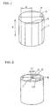
- the expression “axial direction” means a direction parallel to through-holes (an X direction in Fig. 1).
- the expression “section” means, unless otherwise specified, a section of honeycomb structure perpendicular to axial direction.
- Fig. 1 shows one embodiment of the honeycomb structure of the present invention.
- a plurality of honeycomb segments 1 are bonded at their sides parallel to the axial direction (X) of honeycomb segment, using an adhesive, whereby bonded areas 5 are formed.
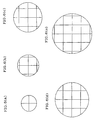
- Fig. 2 shows, in a section of the honeycomb structure of Fig. 1, a relation between the gravity center and the bonded areas 5.
- the important characteristic of the present invention is that, as shown in Fig. 2, the shortest distance (L1) from the gravity center 7 of the section to the bonded areas 5 of the section is 1/10 or less, preferably 1/20 or less, further preferably 1/30 or less, more preferably 1/40 or less of the largest distance (L2) from the gravity center 7 of the section to the circumference 9 of the section.
- L1 is 0, that is, the bonded areas 5 pass the gravity center 7, as shown in Fig. 3.
- the bonded areas 5 pass near the gravity center 7 of the section, most preferably on the gravity center 7, the thermal stress appearing around the center of the section during the use or regeneration of honeycomb structure is liberated, the stress of the whole honeycomb structure is kept low, and generation of cracks is suppressed.
- an intersection 6 of the bonded areas 5 is near the gravity center of the section or preferably on the gravity center.
- the sectional shape of the honeycomb structure of the present invention there is no particular restriction.
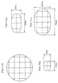
- Various shapes such as circle, ellipse, race track and the like, and various sizes can be used as shown in Figs. 6(a) to 6(e), Figs. 7(f) to 7(i), Figs. 8(j) to 8(l), Figs. 9(m) to 9(o), Fig. 10 and Figs. 11(q) and 11(r).
- Figs. 6(a) to 6(e) Figs. 7(f) to 7(i)
- Figs. 8(j) to 8(l) Figs. 9(m) to 9(o)
- Fig. 10 and Figs. 11(q) and 11(r) In these shapes as well, since the bonded areas pass near each gravity center as shown in Fig. 6(a) to Fig.
- the number of the honeycomb segments used in the honeycomb structure of the present invention can be selected freely depending upon the size of honeycomb structure, etc.
- the number is at least 2 or more, preferably 3 or more, further preferably 5 or more.
- Each honeycomb segment 1 of the present invention has a number of through-holes 13 surrounded by partition walls 11 and extending in the axial direction (X direction), as shown in Fig. 4(a) and Fig. 4(b).
- the sectional shape (cell shape) of each through-hole 13 is preferably any of a triangle, a tetragon, a hexagon and a corrugation for easiness of honeycomb segment production.
- partition walls 11 and through-holes 13 are shown only at part of the top end of honeycomb segment; actually, however, the partition walls 11 and the through-holes 13 are present at the whole part of the top end.
- the density of the cells formed by partition walls i.e. the number of through-holes (cells) per unit area of section is preferably 6 to 2,000 cells/in. 2 (0.9 to 311 cells/cm 2 ), more preferably 50 to 400 cells/in. 2 (7.8 to 62 cells/cm 2 ).
- the honeycomb segment is insufficient in strength and effective GSA (geographical surface area); when the cell density is more than 2,000 cells/in. 2 (311 cells/cm 2 ), the honeycomb segment shows a large pressure loss when a gas flows therethrough.
- each partition wall 11 of the honeycomb segment 1 is preferably 50 to 2,000 ⁇ m.
- the honeycomb segment is insufficient in strength; when the thickness is more than 2,000 ⁇ m, the honeycomb segment is small in effective GSA and, moreover, shows a large pressure loss when a gas flows therethrough.
- each honeycomb segment has a basic tetragonal shape and the shapes of outermost honeycomb segments are matched to the shape of a honeycomb structure to be produced. It is also possible to allow each honeycomb segment to have a fan-shaped section, as shown in Fig. 4(a).
- the main component of the honeycomb segment is preferred to comprise at least one kind of ceramic selected from the group consisting of cordierite, mullite, alumina, spinel, silicon carbide, silicon nitride, lithium aluminum silicate, aluminum titanate and combinations thereof, a Fe-Cr-Al type metal, or metallic Si and SiC, from the standpoint of strength, heat resistance, etc. of honeycomb segment.
- Ceramic carbide which is high in thermal conductivity, is particularly preferred because it releases the heat easily.
- the expression "main component" of honeycomb segment means a component constituting 80% by mass or more of the honeycomb segment.
- the bonded areas 5 are formed by bonding honeycomb segments to each other.
- the thickness of the bonded areas 5 is preferably 0.5 to 6.0 mm, more preferably 0.5 to 3.0 mm, most preferably 0.5 to 2.0 mm.
- the bonding strength obtained is insufficient.
- the thickness is too large, the pressure loss when a gas flows is large.
- the main component of the adhesive forming the bonded areas can be selected from the above-mentioned materials suitable as the main component of honeycomb segment.
- the Si content in the honeycomb segment, specified by Si/(Si+SiC) is preferably 5 to 50% by mass, more preferably 10 to 40% by mass. The reason is that when the Si content is less than 5% by mass, there is no effect of Si addition and, when the Si content is more than 50% by mass, it is impossible to obtain heat resistance and high thermal conductivity which are characteristics of SiC.
- the Si content of the adhesive specified by Si/(Si+SiC) is equal to or higher than that of the honeycomb segment and is 10 to 80% by mass.
- the Si content of the adhesive is lower than that of the honeycomb segment, no required bonding strength is obtained; when the Si content is higher than 80% by mass, no sufficient oxidation resistance is obtained at high temperatures.
- honeycomb structure of the present invention When the honeycomb structure of the present invention is used as a catalyst carrier for purification of exhaust gas emitted from heat engine (e.g. internal combustion engine) or burner (e.g. boiler), or for reforming of liquid fuel or gaseous fuel, it is preferred to load, on the honeycomb structure, a catalyst, for example, a metal having a catalytic activity.
- a metal having a catalytic activity there can be mentioned Pt, Pd and Rh. At least one kind of these metals is preferred to be loaded on the honeycomb structure.
- the honeycomb structure of the present invention when used as a filter (e.g. a diesel particulate filter) for capturing and removing a particulate substance present in a particle-containing fluid, it is preferred that the individual honeycomb segments used therein has such a structure that the partition walls of through-holes have a filtration ability, given through-holes are plugged at one end of honeycomb segment, and the remainder through holes are plugged at the other end of honeycomb segment.
- a filter e.g. a diesel particulate filter
- the particle-containing fluid When a particle-containing fluid is introduced into the honeycomb structure constituted by such honeycomb segments, at its one end, the particle-containing fluid enters the inside of the honeycomb structure from those through-holes not plugged at the one end, passes through porous partition walls having a filtration ability, and enters those through-holes not plugged at the other end of honeycomb structure.
- the particle-containing fluid passes through the partition walls, the particulate substance present in the fluid is captured by the partition walls, and the particulate substance-removed fluid is discharged from the other end of honeycomb structure.
- the honeycomb structure of the present invention When the honeycomb structure of the present invention is used as a filter, the captured particulate substance deposits on the partition walls. As the deposition proceeds, the filter is blocked and its function decreases; therefore, the honeycomb structure is heated periodically by a heating means such as heater or the like to burn and remove the particulate substance and regenerate the filter function. In order to accelerate the burning of the particulate substance during the regeneration, the above-mentioned catalyst may be loaded on the honeycomb structure.
- a raw material powder for honeycomb segment there is used an above-mentioned suitable material, for example, a mixed powder of SiC powder and metallic SiC powder. Thereto are added a binder, for example, methyl cellulose and hydroxypropoxymethyl cellulose. Further, a surfactant and water are added to produce a plastic material. This plastic material is subjected to extrusion molding to produce a plurality of honeycomb segments each having, for example, a partition wall thickness of 0.3 mm, a cell density of 31 cells/cm 2 , and an after-assembling structure of Fig. 1.
- honeycomb segments are dried using, for example, a micro wave and hot air; then, an adhesive having, for example, the same composition as the above plastic material is coated on areas corresponding to the bonded areas 5 of Fig. 1, and the honeycomb segments are bonded; the resulting assembly is dried.
- the dried assembly is heated in, for example, a N 2 atmosphere for debinding and then fired in an inert atmosphere such as Ar or the like, whereby a honeycomb structure of the present invention can be obtained.
- a honeycomb structure having through-holes plugged at either one end can be produced by producing a honeycomb structure by the above method and then plugging the through-holes alternately at each end of the honeycomb structure.
- Loading of a catalyst on the thus-produced honeycomb structure can be conducted by a method ordinarily used by those skilled in the art. For example, a catalyst slurry is wash-coated on a honeycomb structure and the resulting material is dried and fired, whereby a catalyst can be loaded.
- a mixed powder consisting of 75% by mass of a SiC powder and 25% by mass of a metallic Si powder.
- methyl cellulose, hydroxypropoxymethyl cellulose, a surfactant and water were added to produce a plastic material.
- This plastic material was subjected to extrusion molding to obtain a plurality of honeycomb segments each of 0.30 mm in partition wall thickness, 300 cells/in.2 (46.50 cells/cm 2 ) in cell density and 55 mm in length of one side.
- honeycomb segments were dried using a micro wave and hot air and then bonded using an adhesive which was a mixture of a ceramic fiber, a ceramic powder, an organic binder and an inorganic binder, whereby was assembled a cylindrical honeycomb structure of 144 mm in diameter and 153 mm in height, having a sectional shape of Fig. 3 and a thickness of 1 mm in bonded areas 5.
- the honeycomb structure was dried, heated at about 400°C in a N 2 atmosphere for debinding, and fired at about 1,550°C in an Ar atmosphere to obtain a ceramic structure.
- a honeycomb structure was obtained in the same manner as in Example 1 except that the positions of bonded areas 5 were changed as shown in Fig. 12.
- a ceramic-made non-intumescent mat as a holding material was wound round the circumference (side) of each of the honeycomb structures obtained in Example 1 and Comparative Example 1.
- Each of the mat-wound honeycomb structures was stuffed in a SUS 409-made casing, to prepare a canned structure.
- a soot-containing combustion gas generated by combustion of a diesel gas oil was allowed to flow into each canned structure from its lower end [the bottom end in Fig. 1 or 12 (not shown)] and leave from the upper end (the top end in Fig. 1 or 12), whereby the soot was captured inside the honeycomb structure.
- honeycomb structure was then cooled to room temperature, after which a combustion gas containing a given proportion of oxygen was allowed to flow into the honeycomb structure at 650°C from its lower end to burn and remove the soot.
- a filter regeneration test was carried out.
- Example 1 The weight of captured soot was changed from 10 g/l (liter) to 16 g/l and generation of cracks in the honeycomb structure after filter regeneration test was examined visually. The results are shown in Table 1.
- the honeycomb structure obtained in Example 1 generated no cracks up to a soot amount of 14 g/l, while the honeycomb structure obtained in Comparative Example 1 generated cracks at a soot amount of 12 g/l.
- Example 1 0 72 0 No No No Yes Comparative Example 1 27.5 72 1/2.6 No Yes - -
- Example 2 Honeycomb structures were produced in the same manner as in Example 1 except that the positions of gravity center and bonded areas in section were slightly changed and the shortest distance L1 was changed to 1.80 mm, 3.60 mm, 7.20 mm, 10.8 mm or 14.4 mm. A test was conducted in the same manner as in the regeneration test 1. The results are shown in Table 2. L1 L2 L1/L2 Presence of cracks Soot amount (mm) (mm) 10 g/l 12 g/l 14 g/l 16 g/l Example 2 1.8 72 1/40 No No No Yes Example 3 3.6 72 1/20 No No No Yes Example 4 7.2 72 1/10 No No No Yes Example 5 10.8 72 1/6.7 No No Yes Example 6 14.4 72 1/5 No No Yes
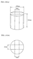
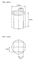
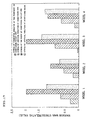
- Fig. 13(a) to Fig. 16(b) Four definite element models shown in Fig. 13(a) to Fig. 16(b) were produced. For these models, the temperature distributions during the regeneration test were determined by numerical analysis and, using the data, thermal stresses were calculated. The results are shown in Fig. 17. The numerical analysis of temperature distribution was made by conducting a calculation for a case wherein when a gas of 650°C was passed under a state that soot of 14 g/l had adhered to the model-inside carrier uniformly. Also in the definite element analysis, there were used, as the properties of material, the measured data of the sample of Example 1.
- the model 1 [Figs. 13(a) and 13(b)] and the model 3 [Figs. 15(a) and 15(b)] are models in which the gravity center is at the sectional center of honeycomb structure and L1/L2 is 1/3.1 and 1/4.1, respectively.
- the model 2 [Figs. 14(a) and 14(b)] and the model 4 [Figs. 16(a) and 16(b)] are models in which the bonded areas pass the gravity center, that is, L1 is 0 (zero). It is clear from Fig. 17 showing the results of simulation that the thermal stresses of the structures of the present invention (the models 2 and 4) are smaller than those of other structures (the models 1 and 3).
- the thermal stress appearing during the use, particularly during the regeneration when local heating tends to arise can be made small; accordingly, generation of cracks can be prevented.
Landscapes
- Chemical & Material Sciences (AREA)
- Geometry (AREA)
- Physics & Mathematics (AREA)
- Chemical Kinetics & Catalysis (AREA)
- Engineering & Computer Science (AREA)
- Health & Medical Sciences (AREA)
- Environmental & Geological Engineering (AREA)
- Ceramic Engineering (AREA)
- Analytical Chemistry (AREA)
- Oil, Petroleum & Natural Gas (AREA)
- General Chemical & Material Sciences (AREA)
- Combustion & Propulsion (AREA)
- Biomedical Technology (AREA)
- General Engineering & Computer Science (AREA)
- Inorganic Chemistry (AREA)
- Life Sciences & Earth Sciences (AREA)
- Geology (AREA)
- Mechanical Engineering (AREA)
- Toxicology (AREA)
- Filtering Materials (AREA)
- Catalysts (AREA)
- Exhaust Gas After Treatment (AREA)
- Processes For Solid Components From Exhaust (AREA)
- Exhaust Gas Treatment By Means Of Catalyst (AREA)
- Press-Shaping Or Shaping Using Conveyers (AREA)
Abstract
Description
| L1 | L2 | L1/L2 | Presence of cracks | ||||
| Soot amount | |||||||
| (mm) | (mm) | 10 g/l | 12 g/l | 14 g/l | 16 g/l | ||
| Example 1 | 0 | 72 | 0 | No | No | No | Yes |
| Comparative Example 1 | 27.5 | 72 | 1/2.6 | No | Yes | - | - |
| L1 | L2 | L1/L2 | Presence of cracks | ||||
| Soot amount | |||||||
| (mm) | (mm) | 10 g/l | 12 g/l | 14 g/l | 16 g/l | ||
| Example 2 | 1.8 | 72 | 1/40 | No | No | No | Yes |
| Example 3 | 3.6 | 72 | 1/20 | No | No | No | Yes |
| Example 4 | 7.2 | 72 | 1/10 | No | No | No | Yes |
| Example 5 | 10.8 | 72 | 1/6.7 | No | No | Yes | |
| Example 6 | 14.4 | 72 | 1/5 | No | No | Yes |
Claims (8)
- A honeycomb structure wherein a plurality of honeycomb segments each having a large number of through-holes surrounded by partition walls and extending in the axial direction of the segment are bonded at the sides of the honeycomb segments parallel to said axial direction and integrated,
characterized in that, in its section perpendicular to said axial direction, the shortest distance (L1) from the gravity center of the section to the bonded areas of honeycomb segments in the section is 1/10 or less of the largest distance (L2) from the gravity center of the section to the circumference of the section. - A honeycomb structure according to Claim 1, characterized in that the shortest distance (L1) is 1/20 or less of the largest distance (L2).
- A honeycomb structure according to Claim 1 or 2, characterized in that the main component of each honeycomb segment comprises at least one kind of ceramic selected from the group consisting of cordierite, mullite, alumina, spinel, silicon carbide, silicon nitride, lithium aluminum silicate, aluminum titanate and combinations thereof, a Fe-Cr-Al type metal, or metallic Si and SiC.
- A honeycomb structure according to any of Claims 1 to 3, characterized in that the honeycomb segments have a catalyst loaded thereon.
- A honeycomb structure according to Claim 4, characterized in that the catalyst is at least one kind selected from Pt, Pd and Rh.
- A honeycomb structure according to any of Claims 1 to 5, characterized in that the through-holes of the honeycomb segments has a sectional shape of any of a triangle, a tetragon and a hexagon.
- A honeycomb structure according to any of Claims 1 to 6, characterized in that, in each honeycomb segment, the partition walls surrounding the through-holes have a filtration ability, given through-holes are plugged at one end of the honeycomb segment, and the residual through-holes are plugged at the other end of the honeycomb segment.
- A honeycomb structure according to Claim 7, characterized by being used as a filter for capturing and removing a particulate substance present in a particle-containing fluid.
Applications Claiming Priority (3)
| Application Number | Priority Date | Filing Date | Title |
|---|---|---|---|
| JP2001083736A JP2002273130A (en) | 2001-03-22 | 2001-03-22 | Honeycomb structure |
| JP2001083736 | 2001-03-22 | ||
| PCT/JP2002/002643 WO2002076579A1 (en) | 2001-03-22 | 2002-03-20 | Honeycomb structural body |
Publications (3)
| Publication Number | Publication Date |
|---|---|
| EP1371406A1 true EP1371406A1 (en) | 2003-12-17 |
| EP1371406A4 EP1371406A4 (en) | 2004-09-22 |
| EP1371406B1 EP1371406B1 (en) | 2007-08-01 |
Family
ID=18939516
Family Applications (1)
| Application Number | Title | Priority Date | Filing Date |
|---|---|---|---|
| EP02705376A Revoked EP1371406B1 (en) | 2001-03-22 | 2002-03-20 | Honeycomb structural body |
Country Status (6)
| Country | Link |
|---|---|
| US (1) | US7531145B2 (en) |
| EP (1) | EP1371406B1 (en) |
| JP (1) | JP2002273130A (en) |
| DE (1) | DE60221504T2 (en) |
| PL (1) | PL374099A1 (en) |
| WO (1) | WO2002076579A1 (en) |
Cited By (8)
| Publication number | Priority date | Publication date | Assignee | Title |
|---|---|---|---|---|
| EP1736459A1 (en) * | 2005-06-24 | 2006-12-27 | Ibiden Co., Ltd. | Honeycomb structured body |
| EP1736220A1 (en) * | 2005-06-24 | 2006-12-27 | Ibiden Co., Ltd. | Honeycomb structured body |
| EP1584801A3 (en) * | 2004-04-05 | 2007-04-18 | Arvin Technologies, Inc. | Device for purifying a motor vehicle exhaust gas, especially for a particle filter and motor vehicle comprising such device |
| WO2008009837A1 (en) * | 2006-07-18 | 2008-01-24 | Saint-Gobain Centre De Recherches Et D'etudes Europeen | Filter comprising a plurality of honeycomb elements joined together in an offset assembly |
| FR2903918A1 (en) * | 2006-07-18 | 2008-01-25 | Saint Gobain Ct Recherches | Particle-laden gas e.g. hydrocarbon, filtering structure for e.g. diesel engine, has ducts separated by porous walls and closed by plugs to define inlet chambers and outlet chambers such that gas to be filtered passes through walls |
| WO2008037521A1 (en) | 2006-09-25 | 2008-04-03 | Robert Bosch Gmbh | Filter element, especially for filtering the exhaust gases of an internal combustion engine |
| US7846229B2 (en) | 2004-05-06 | 2010-12-07 | Ibiden Co., Ltd. | Honeycomb structural body and manufacturing method thereof |
| US7851041B2 (en) | 2005-06-24 | 2010-12-14 | Ibiden Co., Ltd. | Honeycomb structure |
Families Citing this family (24)
| Publication number | Priority date | Publication date | Assignee | Title |
|---|---|---|---|---|
| JP3893049B2 (en) * | 2001-11-20 | 2007-03-14 | 日本碍子株式会社 | Honeycomb structure and manufacturing method thereof |
| ATE374069T1 (en) * | 2002-03-15 | 2007-10-15 | Ibiden Co Ltd | CERAMIC FILTER FOR EXHAUST GAS CLEANING |
| EP1550646A4 (en) * | 2002-10-07 | 2006-04-26 | Ibiden Co Ltd | STRUCTURAL BODY IN HONEYCOMB |
| EP1506948B1 (en) | 2002-10-07 | 2013-02-27 | Ibiden Co., Ltd. | Honeycomb structural body |
| US7556665B2 (en) * | 2003-03-19 | 2009-07-07 | Ngk Insulators, Ltd. | Honeycomb structure |
| PL1686108T3 (en) * | 2003-11-12 | 2012-02-29 | Ngk Insulators Ltd | Honeycomb structure |
| WO2005099865A1 (en) * | 2004-04-05 | 2005-10-27 | Ibiden Co., Ltd. | Honeycomb structure, method of manufacturing honeycomb structure, and exhaust emission control device |
| CN1906141B (en) * | 2004-12-27 | 2010-11-03 | 揖斐电株式会社 | Honeycomb structure and sealing material layer |
| JP5237630B2 (en) * | 2005-02-01 | 2013-07-17 | イビデン株式会社 | Honeycomb structure |
| JP4753784B2 (en) * | 2005-06-24 | 2011-08-24 | イビデン株式会社 | Honeycomb structure and exhaust gas purification device |
| WO2006137151A1 (en) | 2005-06-24 | 2006-12-28 | Ibiden Co., Ltd. | Honeycomb structure and exhaust gas purifier |
| JP4753785B2 (en) * | 2005-06-24 | 2011-08-24 | イビデン株式会社 | Honeycomb structure |
| DE102006057280A1 (en) * | 2006-12-05 | 2008-06-12 | Robert Bosch Gmbh | By extrusion produced filter element for filtering exhaust gases of a diesel internal combustion engine |
| CN105107279B (en) * | 2007-02-26 | 2017-04-12 | 唐纳森公司 | Air filter arrangement, air cleaner assembly and methods |
| EP2160231A2 (en) * | 2007-05-04 | 2010-03-10 | Dow Global Technologies Inc. | Improved honeycomb filters |
| US8728193B2 (en) | 2007-09-07 | 2014-05-20 | Donaldson Company, Inc. | Air filter assembly; components thereof and methods |
| WO2009066388A1 (en) * | 2007-11-21 | 2009-05-28 | Ibiden Co., Ltd. | Honeycomb structure and process for producing the same |
| US8491684B2 (en) * | 2009-02-27 | 2013-07-23 | Donaldson Company, Inc. | Filter cartridge; components thereof; and methods |
| JP2010227755A (en) * | 2009-03-26 | 2010-10-14 | Ngk Insulators Ltd | Ceramic honeycomb structure |
| DE102010022539A1 (en) * | 2010-06-02 | 2011-12-08 | Bayerische Motoren Werke Aktiengesellschaft | Particle filter arrangement for arranging in exhaust flow channel of internal-combustion engine-driven motor vehicle, has housing with exhaust inlet and exhaust outlet with filter body |
| JP2013024221A (en) * | 2011-07-26 | 2013-02-04 | Ngk Insulators Ltd | Honeycomb structure, honeycomb catalyst body, and exhaust gas processor |
| ITMI20122251A1 (en) * | 2012-12-28 | 2014-06-29 | Eni Spa | MULTI-TEXTURED REACTOR FOR CHEMICAL PROCESSES WITH HIGH HEAT EXCHANGE |
| JP6022985B2 (en) * | 2013-03-29 | 2016-11-09 | 日本碍子株式会社 | Honeycomb structure |
| DE102019107386A1 (en) * | 2019-03-22 | 2020-09-24 | Eberspächer Exhaust Technology GmbH & Co. KG | Substrate for an exhaust gas treatment unit |
Family Cites Families (15)
| Publication number | Priority date | Publication date | Assignee | Title |
|---|---|---|---|---|
| JPS5839799B2 (en) * | 1978-05-02 | 1983-09-01 | 日産自動車株式会社 | Manufacturing method of large honeycomb structure |
| US4335783A (en) * | 1980-11-10 | 1982-06-22 | Corning Glass Works | Method for improving thermal shock resistance of honeycombed structures formed from joined cellular segments |
| JPS6151240A (en) | 1984-08-20 | 1986-03-13 | Mitsubishi Electric Corp | Data processor |
| JPH0710330B2 (en) * | 1987-03-30 | 1995-02-08 | 株式会社神戸製鋼所 | Dry dehumidifier |
| US4849399A (en) * | 1987-04-16 | 1989-07-18 | Allied-Signal Inc. | Catalyst for the reduction of the ignition temperature of diesel soot |
| JPH0550022A (en) | 1991-08-20 | 1993-03-02 | Cosmo Sogo Kenkyusho:Kk | Coating method |
| JPH0550022U (en) * | 1991-12-10 | 1993-07-02 | バブコック日立株式会社 | Catalytic reactor |
| JPH07241422A (en) * | 1994-03-07 | 1995-09-19 | Matsushita Electric Ind Co Ltd | Fibrous exhaust gas filter |
| JP3121497B2 (en) | 1994-07-14 | 2000-12-25 | イビデン株式会社 | Ceramic structure |
| JP3971027B2 (en) * | 1998-06-25 | 2007-09-05 | イビデン株式会社 | Ceramic structure bonding apparatus and bonding method |
| JP2000210517A (en) * | 1999-01-20 | 2000-08-02 | Ngk Insulators Ltd | Method for holding ceramic filter, filter pack and filter device |
| JP2000210217A (en) | 1999-01-25 | 2000-08-02 | Hitachi Metals Techno Ltd | 24-hour circulation bathtub system |
| JP2000279929A (en) * | 1999-03-30 | 2000-10-10 | Shinko Engineering Co Ltd | Method and apparatus for fermenting organic waste |
| JP3967034B2 (en) | 1999-03-30 | 2007-08-29 | イビデン株式会社 | Manufacturing method of ceramic filter unit |
| JP4511065B2 (en) | 2000-06-05 | 2010-07-28 | 日本碍子株式会社 | Honeycomb structure, honeycomb filter, and manufacturing method thereof |
-
2001
- 2001-03-22 JP JP2001083736A patent/JP2002273130A/en active Pending
-
2002
- 2002-03-20 WO PCT/JP2002/002643 patent/WO2002076579A1/en not_active Ceased
- 2002-03-20 PL PL02374099A patent/PL374099A1/en unknown
- 2002-03-20 US US10/472,274 patent/US7531145B2/en not_active Expired - Lifetime
- 2002-03-20 DE DE60221504T patent/DE60221504T2/en not_active Revoked
- 2002-03-20 EP EP02705376A patent/EP1371406B1/en not_active Revoked
Cited By (16)
| Publication number | Priority date | Publication date | Assignee | Title |
|---|---|---|---|---|
| US7468086B2 (en) | 2004-04-05 | 2008-12-23 | Et Us Holdings Llc | Device for cleaning vehicular exhaust gas, in particular a diesel exhaust particle filter, and vehicle comprising such device |
| EP1584801A3 (en) * | 2004-04-05 | 2007-04-18 | Arvin Technologies, Inc. | Device for purifying a motor vehicle exhaust gas, especially for a particle filter and motor vehicle comprising such device |
| US7976605B2 (en) | 2004-05-06 | 2011-07-12 | Ibiden Co. Ltd. | Honeycomb structural body and manufacturing method thereof |
| US7846229B2 (en) | 2004-05-06 | 2010-12-07 | Ibiden Co., Ltd. | Honeycomb structural body and manufacturing method thereof |
| US7892623B2 (en) | 2005-06-24 | 2011-02-22 | Ibiden Co., Ltd | Honeycomb structured body, manufacturing device of honeycomb structured body and manufacturing method of honeycomb structured body |
| CN100528341C (en) * | 2005-06-24 | 2009-08-19 | 揖斐电株式会社 | Honeycomb structure |
| US7851041B2 (en) | 2005-06-24 | 2010-12-14 | Ibiden Co., Ltd. | Honeycomb structure |
| EP1736459A1 (en) * | 2005-06-24 | 2006-12-27 | Ibiden Co., Ltd. | Honeycomb structured body |
| EP1736220A1 (en) * | 2005-06-24 | 2006-12-27 | Ibiden Co., Ltd. | Honeycomb structured body |
| FR2903919A1 (en) * | 2006-07-18 | 2008-01-25 | Saint Gobain Ct Recherches | FILTER COMPRISING A PLURALITY OF HONEYCOMB ELEMENTS MADE IN A DECENTRATED ASSEMBLY |
| FR2903918A1 (en) * | 2006-07-18 | 2008-01-25 | Saint Gobain Ct Recherches | Particle-laden gas e.g. hydrocarbon, filtering structure for e.g. diesel engine, has ducts separated by porous walls and closed by plugs to define inlet chambers and outlet chambers such that gas to be filtered passes through walls |
| WO2008009837A1 (en) * | 2006-07-18 | 2008-01-24 | Saint-Gobain Centre De Recherches Et D'etudes Europeen | Filter comprising a plurality of honeycomb elements joined together in an offset assembly |
| EA014622B1 (en) * | 2006-07-18 | 2010-12-30 | Сэн-Гобэн Сантр Де Решерш Э Д'Этюд Эропеен | Filter comprising a plurality of honeycomb elements joined together in an offset assembly |
| US7998425B2 (en) | 2006-07-18 | 2011-08-16 | Saint-Gobain Centre De Recherches Et D'etudes Europeen | Filter comprising a plurality of honeycomb elements joined together in an offset assembly |
| CN101489646B (en) * | 2006-07-18 | 2011-11-16 | 欧洲技术研究圣戈班中心 | Filters consisting of multiple honeycomb elements brought together in an eccentric assembly |
| WO2008037521A1 (en) | 2006-09-25 | 2008-04-03 | Robert Bosch Gmbh | Filter element, especially for filtering the exhaust gases of an internal combustion engine |
Also Published As
| Publication number | Publication date |
|---|---|
| WO2002076579A1 (en) | 2002-10-03 |
| DE60221504T2 (en) | 2008-04-24 |
| PL374099A1 (en) | 2005-09-19 |
| EP1371406A4 (en) | 2004-09-22 |
| DE60221504D1 (en) | 2007-09-13 |
| JP2002273130A (en) | 2002-09-24 |
| US7531145B2 (en) | 2009-05-12 |
| US20040093858A1 (en) | 2004-05-20 |
| EP1371406B1 (en) | 2007-08-01 |
Similar Documents
| Publication | Publication Date | Title |
|---|---|---|
| US7531145B2 (en) | Honeycomb structure | |
| US7037567B2 (en) | Honeycomb structure | |
| US8029591B2 (en) | Inorganic fiber aggregate, method for manufacturing inorganic fiber aggregate, honeycomb structure, method for manufacturing honeycomb structure, and exhaust gas purifier | |
| US6984253B2 (en) | Honeycomb filter | |
| US7384441B2 (en) | Honeycomb filter | |
| US7244284B2 (en) | Honeycomb filter | |
| EP1382374B1 (en) | Honeycomb structural body and assembly thereof | |
| US7041359B2 (en) | Honeycomb structure and assembly thereof | |
| US7510755B2 (en) | Honeycomb structure and method for producing same | |
| EP1283067B1 (en) | Honeycomb filter for purifying exhaust gas | |
| EP1291061A1 (en) | Honeycomb structure and honeycomb filter, and method of producing them | |
| US7087286B2 (en) | Honeycomb structure and assembly thereof | |
| US20040211164A1 (en) | Honeycomb structural body and method of manufacturing the structural body | |
| EP1473445A1 (en) | Honeycomb structure | |
| US7078086B2 (en) | Honeycomb structure and assembly thereof | |
| WO2001015877A1 (en) | Corrugated wall honeycomb structure and production method thereof | |
| US8236404B2 (en) | Honeycomb structure |
Legal Events
| Date | Code | Title | Description |
|---|---|---|---|
| PUAI | Public reference made under article 153(3) epc to a published international application that has entered the european phase |
Free format text: ORIGINAL CODE: 0009012 |
|
| 17P | Request for examination filed |
Effective date: 20031001 |
|
| AK | Designated contracting states |
Kind code of ref document: A1 Designated state(s): AT BE CH CY DE DK ES FI FR GB GR IE IT LI LU MC NL PT SE TR |
|
| AX | Request for extension of the european patent |
Extension state: AL LT LV MK RO SI |
|
| A4 | Supplementary search report drawn up and despatched |
Effective date: 20040805 |
|
| 17Q | First examination report despatched |
Effective date: 20050216 |
|
| GRAP | Despatch of communication of intention to grant a patent |
Free format text: ORIGINAL CODE: EPIDOSNIGR1 |
|
| GRAC | Information related to communication of intention to grant a patent modified |
Free format text: ORIGINAL CODE: EPIDOSCIGR1 |
|
| GRAS | Grant fee paid |
Free format text: ORIGINAL CODE: EPIDOSNIGR3 |
|
| GRAA | (expected) grant |
Free format text: ORIGINAL CODE: 0009210 |
|
| AK | Designated contracting states |
Kind code of ref document: B1 Designated state(s): DE FR |
|
| REF | Corresponds to: |
Ref document number: 60221504 Country of ref document: DE Date of ref document: 20070913 Kind code of ref document: P |
|
| ET | Fr: translation filed | ||
| PLBI | Opposition filed |
Free format text: ORIGINAL CODE: 0009260 |
|
| PLBI | Opposition filed |
Free format text: ORIGINAL CODE: 0009260 |
|
| 26 | Opposition filed |
Opponent name: THE DOW CHEMICAL COMPANY Effective date: 20080422 |
|
| PLAX | Notice of opposition and request to file observation + time limit sent |
Free format text: ORIGINAL CODE: EPIDOSNOBS2 |
|
| 26 | Opposition filed |
Opponent name: THE DOW CHEMICAL COMPANY Effective date: 20080422 Opponent name: SAINT-GOBAIN CENTRE DE RECHERCHES ET D'ETUDES EURO Effective date: 20080428 |
|
| PLAF | Information modified related to communication of a notice of opposition and request to file observations + time limit |
Free format text: ORIGINAL CODE: EPIDOSCOBS2 |
|
| PLAF | Information modified related to communication of a notice of opposition and request to file observations + time limit |
Free format text: ORIGINAL CODE: EPIDOSCOBS2 |
|
| PGFP | Annual fee paid to national office [announced via postgrant information from national office to epo] |
Ref country code: FR Payment date: 20100318 Year of fee payment: 9 |
|
| RDAF | Communication despatched that patent is revoked |
Free format text: ORIGINAL CODE: EPIDOSNREV1 |
|
| PGFP | Annual fee paid to national office [announced via postgrant information from national office to epo] |
Ref country code: DE Payment date: 20100331 Year of fee payment: 9 |
|
| RDAG | Patent revoked |
Free format text: ORIGINAL CODE: 0009271 |
|
| STAA | Information on the status of an ep patent application or granted ep patent |
Free format text: STATUS: PATENT REVOKED |
|
| 27W | Patent revoked |
Effective date: 20100725 |