EP1370208B1 - Leg ulcer, lymphoedema and dvt vibratory treatment device - Google Patents
Leg ulcer, lymphoedema and dvt vibratory treatment device Download PDFInfo
- Publication number
- EP1370208B1 EP1370208B1 EP02703694A EP02703694A EP1370208B1 EP 1370208 B1 EP1370208 B1 EP 1370208B1 EP 02703694 A EP02703694 A EP 02703694A EP 02703694 A EP02703694 A EP 02703694A EP 1370208 B1 EP1370208 B1 EP 1370208B1
- Authority
- EP
- European Patent Office
- Prior art keywords
- pad
- drive unit
- motor
- cover
- strap
- Prior art date
- Legal status (The legal status is an assumption and is not a legal conclusion. Google has not performed a legal analysis and makes no representation as to the accuracy of the status listed.)
- Expired - Lifetime
Links
- 238000011282 treatment Methods 0.000 title claims description 24
- 208000002502 lymphedema Diseases 0.000 title claims description 13
- 206010025282 Lymphoedema Diseases 0.000 title claims description 12
- 208000005230 Leg Ulcer Diseases 0.000 title description 4
- 206010040943 Skin Ulcer Diseases 0.000 title description 4
- 208000025865 Ulcer Diseases 0.000 claims description 51
- 231100000397 ulcer Toxicity 0.000 claims description 50
- 239000000463 material Substances 0.000 claims description 23
- 206010051055 Deep vein thrombosis Diseases 0.000 claims description 13
- 206010047249 Venous thrombosis Diseases 0.000 claims description 13
- 241001465754 Metazoa Species 0.000 claims description 5
- 230000000694 effects Effects 0.000 claims description 5
- 239000007788 liquid Substances 0.000 claims description 4
- 238000003825 pressing Methods 0.000 claims description 4
- 238000001816 cooling Methods 0.000 claims description 3
- 239000004744 fabric Substances 0.000 claims description 3
- 230000010355 oscillation Effects 0.000 claims description 3
- 230000005611 electricity Effects 0.000 claims description 2
- 230000000149 penetrating effect Effects 0.000 claims description 2
- 210000002414 leg Anatomy 0.000 description 32
- 230000001133 acceleration Effects 0.000 description 14
- 230000035876 healing Effects 0.000 description 14
- 210000003423 ankle Anatomy 0.000 description 12
- 210000003414 extremity Anatomy 0.000 description 12
- 230000009467 reduction Effects 0.000 description 12
- 210000003127 knee Anatomy 0.000 description 11
- 238000000034 method Methods 0.000 description 10
- 230000006835 compression Effects 0.000 description 9
- 238000007906 compression Methods 0.000 description 9
- 239000004677 Nylon Substances 0.000 description 7
- 238000005259 measurement Methods 0.000 description 7
- 229920001778 nylon Polymers 0.000 description 7
- 210000003462 vein Anatomy 0.000 description 7
- 210000003491 skin Anatomy 0.000 description 6
- 238000002560 therapeutic procedure Methods 0.000 description 6
- 210000000416 exudates and transudate Anatomy 0.000 description 5
- 230000003442 weekly effect Effects 0.000 description 5
- 206010042674 Swelling Diseases 0.000 description 4
- 208000007536 Thrombosis Diseases 0.000 description 4
- 230000017531 blood circulation Effects 0.000 description 4
- 210000000988 bone and bone Anatomy 0.000 description 4
- 244000309466 calf Species 0.000 description 4
- 238000001356 surgical procedure Methods 0.000 description 4
- 230000008961 swelling Effects 0.000 description 4
- 210000001519 tissue Anatomy 0.000 description 4
- 238000001266 bandaging Methods 0.000 description 3
- 230000009286 beneficial effect Effects 0.000 description 3
- 230000005540 biological transmission Effects 0.000 description 3
- 239000008280 blood Substances 0.000 description 3
- 210000004369 blood Anatomy 0.000 description 3
- 238000011109 contamination Methods 0.000 description 3
- 230000006378 damage Effects 0.000 description 3
- 238000011038 discontinuous diafiltration by volume reduction Methods 0.000 description 3
- 239000012530 fluid Substances 0.000 description 3
- 208000015181 infectious disease Diseases 0.000 description 3
- 238000011160 research Methods 0.000 description 3
- 238000002604 ultrasonography Methods 0.000 description 3
- 229920000742 Cotton Polymers 0.000 description 2
- 208000004210 Pressure Ulcer Diseases 0.000 description 2
- 208000000558 Varicose Ulcer Diseases 0.000 description 2
- 238000009825 accumulation Methods 0.000 description 2
- 230000001464 adherent effect Effects 0.000 description 2
- 230000008901 benefit Effects 0.000 description 2
- 230000015572 biosynthetic process Effects 0.000 description 2
- 230000008859 change Effects 0.000 description 2
- 230000004087 circulation Effects 0.000 description 2
- 210000004207 dermis Anatomy 0.000 description 2
- 230000006870 function Effects 0.000 description 2
- 230000006872 improvement Effects 0.000 description 2
- 230000007774 longterm Effects 0.000 description 2
- 210000004880 lymph fluid Anatomy 0.000 description 2
- 230000001926 lymphatic effect Effects 0.000 description 2
- 230000004044 response Effects 0.000 description 2
- 238000005549 size reduction Methods 0.000 description 2
- 238000012360 testing method Methods 0.000 description 2
- 208000037997 venous disease Diseases 0.000 description 2
- 230000029663 wound healing Effects 0.000 description 2
- 200000000007 Arterial disease Diseases 0.000 description 1
- 208000017667 Chronic Disease Diseases 0.000 description 1
- 206010053567 Coagulopathies Diseases 0.000 description 1
- 206010010356 Congenital anomaly Diseases 0.000 description 1
- 206010010535 Congenital lymphoedema Diseases 0.000 description 1
- 241000699670 Mus sp. Species 0.000 description 1
- 208000032056 Radiation Fibrosis Syndrome Diseases 0.000 description 1
- 206010067953 Radiation fibrosis Diseases 0.000 description 1
- 206010039509 Scab Diseases 0.000 description 1
- 206010046996 Varicose vein Diseases 0.000 description 1
- 208000027418 Wounds and injury Diseases 0.000 description 1
- 238000002679 ablation Methods 0.000 description 1
- 239000000853 adhesive Substances 0.000 description 1
- 230000001070 adhesive effect Effects 0.000 description 1
- 238000009530 blood pressure measurement Methods 0.000 description 1
- 208000020670 canker sore Diseases 0.000 description 1
- 230000001684 chronic effect Effects 0.000 description 1
- 230000035602 clotting Effects 0.000 description 1
- 238000007796 conventional method Methods 0.000 description 1
- 230000006735 deficit Effects 0.000 description 1
- 238000011161 development Methods 0.000 description 1
- 229940079593 drug Drugs 0.000 description 1
- 239000003814 drug Substances 0.000 description 1
- 230000002500 effect on skin Effects 0.000 description 1
- 210000002615 epidermis Anatomy 0.000 description 1
- 230000002349 favourable effect Effects 0.000 description 1
- 230000036571 hydration Effects 0.000 description 1
- 238000006703 hydration reaction Methods 0.000 description 1
- 208000014674 injury Diseases 0.000 description 1
- 238000002955 isolation Methods 0.000 description 1
- 230000003902 lesion Effects 0.000 description 1
- 229940057995 liquid paraffin Drugs 0.000 description 1
- 210000002751 lymph Anatomy 0.000 description 1
- 230000032630 lymph circulation Effects 0.000 description 1
- 210000001165 lymph node Anatomy 0.000 description 1
- 210000004324 lymphatic system Anatomy 0.000 description 1
- 238000004519 manufacturing process Methods 0.000 description 1
- 238000011369 optimal treatment Methods 0.000 description 1
- 206010033675 panniculitis Diseases 0.000 description 1
- 239000012188 paraffin wax Substances 0.000 description 1
- 239000004033 plastic Substances 0.000 description 1
- 229920003023 plastic Polymers 0.000 description 1
- 238000011321 prophylaxis Methods 0.000 description 1
- 230000000241 respiratory effect Effects 0.000 description 1
- 230000000284 resting effect Effects 0.000 description 1
- 230000000717 retained effect Effects 0.000 description 1
- 239000000523 sample Substances 0.000 description 1
- 238000012216 screening Methods 0.000 description 1
- 238000009958 sewing Methods 0.000 description 1
- 208000017520 skin disease Diseases 0.000 description 1
- 230000007480 spreading Effects 0.000 description 1
- 238000003892 spreading Methods 0.000 description 1
- 210000004304 subcutaneous tissue Anatomy 0.000 description 1
- 239000008399 tap water Substances 0.000 description 1
- 235000020679 tap water Nutrition 0.000 description 1
- 210000003371 toe Anatomy 0.000 description 1
- 230000001052 transient effect Effects 0.000 description 1
- 230000036269 ulceration Effects 0.000 description 1
- 210000000689 upper leg Anatomy 0.000 description 1
- 208000027185 varicose disease Diseases 0.000 description 1
- 230000000007 visual effect Effects 0.000 description 1
Images








Classifications
-
- A—HUMAN NECESSITIES
- A61—MEDICAL OR VETERINARY SCIENCE; HYGIENE
- A61H—PHYSICAL THERAPY APPARATUS, e.g. DEVICES FOR LOCATING OR STIMULATING REFLEX POINTS IN THE BODY; ARTIFICIAL RESPIRATION; MASSAGE; BATHING DEVICES FOR SPECIAL THERAPEUTIC OR HYGIENIC PURPOSES OR SPECIFIC PARTS OF THE BODY
- A61H23/00—Percussion or vibration massage, e.g. using supersonic vibration; Suction-vibration massage; Massage with moving diaphragms
- A61H23/02—Percussion or vibration massage, e.g. using supersonic vibration; Suction-vibration massage; Massage with moving diaphragms with electric or magnetic drive
- A61H23/0254—Percussion or vibration massage, e.g. using supersonic vibration; Suction-vibration massage; Massage with moving diaphragms with electric or magnetic drive with rotary motor
- A61H23/0263—Percussion or vibration massage, e.g. using supersonic vibration; Suction-vibration massage; Massage with moving diaphragms with electric or magnetic drive with rotary motor using rotating unbalanced masses
-
- A—HUMAN NECESSITIES
- A61—MEDICAL OR VETERINARY SCIENCE; HYGIENE
- A61H—PHYSICAL THERAPY APPARATUS, e.g. DEVICES FOR LOCATING OR STIMULATING REFLEX POINTS IN THE BODY; ARTIFICIAL RESPIRATION; MASSAGE; BATHING DEVICES FOR SPECIAL THERAPEUTIC OR HYGIENIC PURPOSES OR SPECIFIC PARTS OF THE BODY
- A61H1/00—Apparatus for passive exercising; Vibrating apparatus; Chiropractic devices, e.g. body impacting devices, external devices for briefly extending or aligning unbroken bones
- A61H1/02—Stretching or bending or torsioning apparatus for exercising
- A61H1/0237—Stretching or bending or torsioning apparatus for exercising for the lower limbs
Definitions
- the present invention relates to a vibratory massage device for the treatment of open sore ulcers, lymphoedema and deep vein thrombosis (DVT) as they affect the human or animal body.
- DVT deep vein thrombosis
- cycloidal vibration has beneficial effects in improving blood circulation, joint mobility, and respiratory conditions, and relieving tension.
- Such vibration is in the frequency range of 15 to 75 Hz with an amplitude varying between 0.1 and 0.5 mm, depending on the orthogonal direction.
- Decubitus ulcers are caused by continuous pressure at specific points of the body when a patient is immobile for extended periods of time. It is known that vibration can assist in preventing the development of such sores and US-A-5606754 suggests a bed which has vibration means to reduce the incidence of bed sores.
- Ulcers are caused by underlying blood circulatory problems, either venous or arterial disease. If the venous system in the leg fails to work normally, the pressure in the leg veins rises. This reduces circulation in the lower leg and leads to swelling and discomfort. The skin changes and becomes vulnerable and is poor at healing. A small injury, bite or minor infection, that would normally heal quickly, instead progresses and an area of skin break down results in the formation of an ulcer. Varicose veins, a previous deep vein thrombosis, or primary failure of the valves in the veins can all contribute to ulcers.
- the current method of treatment is to cover the affected skin area with a dressing, in order to keep the skin moist and prevent infection from entering the sore, and to immobilise the sore in order to facilitate healing.
- a dressing in order to keep the skin moist and prevent infection from entering the sore, and to immobilise the sore in order to facilitate healing.
- some patients suffer from venous ulcers for extended periods of time in the order of months or even years before they heal, if ever. There is an evident need for more efficient treatment of ulcers.
- US-A-5948009 discloses an ablation electrode for treating canker sore in which vibratory massage is applied to create a lesion. This is said to create the conditions for subsequent healing.
- Lymphoedema is the chronic swelling of subcutaneous tissues due to the accumulation of excessive lymph fluid. The accumulation of lymph fluid results from impairment to the normal clearing function of the lymphatic system and/or from an excessive production of lymph. Lymphoedema is divided into two broad classes according to aetiology. Primary lymphoedema is a relatively uncommon, chronic condition which may be due to such causes as Milroy's Disease or congenital anomalies. Secondary lymphoedema, which is much more common, results from the destruction of, or damage to, formerly functioning lymphatic channels, such as surgical removal of lymph nodes or post radiation fibrosis, among other causes.
- Deep Vein Thrombosis refers to the formation of a thrombus (blood clot) within a deep vein, commonly in the thigh or calf.
- the blood clot can either partially or completely block the flow of blood in the vein.
- Compression therapy is used to aid circulation to prevent patients at risk of clotting from developing DVT.
- pneumatic compression therapy is used on patients at risk of DVT and this treatment is often used prior too and after surgery, especially limb surgery such as knee surgery and joint replacement where the risk of DVT is often greater.
- GB-A-2096899 discloses a vibratory therapy apparatus comprising a drive unit adapted to deliver mechanical vibrations at its surface in three orthogonal directions at a frequency in each orthogonal direction of between 15 and 75 Hz, and a pad connected to said drive unit.
- the apparatus is known to be useful in the treatment of various medical conditions.
- an ulcer, lymphoedema and deep vein thrombosis treatment device comprising a device as disclosed in GB-A-2096899 characterised in that the device further comprises a detachable cover for the pad and pressure applying means in the form of a strap by means of which the pad may be secured to the limb of the animal or human and by which the pad may be pressed against said limb; in that the amplitude of vibration in each orthogonal direction is between 0.1 and 0.5 mm; and in that said strap is integrally formed with the cover.
- the area over which a given level of pressure in excess of 1333 Pa (10 mmHg), preferably 2666 Pa (20 mmHg), is applied to the limb by the pad is increased by at least 25%, preferably 50%, by application of said pressure applying means.
- the drive unit is substantially cylindrical. It may have a casing mounting a motor having an armature parallel the axis of the cylinder.
- the motor may drive an eccentrically mounted weight to provide oscillations of the casing in a radial plane.
- the motor may be mounted through flexible mountings in the casing so that a component of the vibration is created in an axial direction of the armature.
- GB-A-2096899 describes a conventional analogue control of the universal AC motor for its vibration device, which control is found not to provide a smooth delivery of power to the motor so that, at some frequencies, the three-dimensional nature of the vibrations is lost.
- the motor is electrically powered from mains AC electricity, the drive unit including digital control means to ensure smooth supply of energy to the motor.
- Said digital control means preferably comprises:
- a low voltage transformer is disposed between the power supply and detector.
- a rectifier may convert the power supply to the motor to DC, if the motor is a DC motor.
- Preferably said number is adjustable to vary the power supplied to the motor, and hence its speed of rotation and hence said frequency.
- said counter is capable of providing about 250 counts in each half cycle of the power supply.
- the drive unit operates at a frequency of between 30 and 60 Hz.
- Said pad preferably comprises a rigid frame connected to said drive unit and through which mechanic vibrations are transmitted, and cushioning overlying the frame.
- the device is useful in a method of treatment of ulcers of the human or animal body, which method comprises the step of subjecting the body in the area of the ulcer to mechanical vibrations for an effective period of time, said vibrations having a frequency of between 15 and 75 Hz, and an amplitude of between 0.1 and 0.5 mm.
- the device is also useful in a method of treatment of lymphoedema of a patient, which method comprises the step of subjecting the body in the area of the lymphoedema to mechanical vibrations for an effective period of time, said vibrations having a frequency of between 15 and 75 Hz, and an amplitude of between 0.1 and 0.5 mm.
- the device is also useful in a method of prophylactic treatment of deep vein thrombosis, which method comprises the step of subjecting the body in the area of the thrombosis to mechanical vibrations for an effective period of time, said vibrations having a frequency of between 15 and 75 Hz, and an amplitude of between 0.1 and 0.5 mm.
- Said vibrations when provided by the device of the present invention have, in each case, components in three orthogonal directions, said frequency being the same or different in each direction, and said amplitude being the same or different in each direction.
- Preferably said period is more than fifteen minutes, ideally about thirty minutes.
- the treatment is preferably repeated three times a day.
- said treatment is applied by a vibratory device comprising a pad, and said method also involves the application of pressure by the pad against the tissue of the patient.
- the pad is preferably a cushioned frame fixed to a vibratory drive unit.
- the pad is applied by said pressure applying means to the leg of a patient suffering from ulcers, lymphoedema or deep vein thrombosis and so that, in use, the device delivers vibrations in the leg of the patient at a frequency of between 20 and 50 Hz, and with an RM.S acceleration in the axial direction of the tibial bone of between 5 and 15 ms -2 , and in a radial plane with respect to the tibial bone with an RMS acceleration of between 2 and 5 ms -2 .
- the device delivers vibrations in the leg of the patient at a frequency of about 30 Hz, and with an RMS acceleration, in the axial direction of the tibial bone, of about 10 ms -2 , and, in a radial plane with respect to the tibial bone, with an RMS acceleration of between 2 and 5 ms -2 .
- the first is the three-dimensional aspect of the vibration; some benefit is experienced with two-dimensional vibration but significantly enhanced effects have been noted with three-dimensional "cycloidal" vibration, particularly when employing the motor control described above which provides smooth power delivery to the motor.
- the second is the pressure applying means, which serves to unite the patient's limb with the device and ensures deep transmission of the vibrations into the flesh of the patient. This is particularly the case given the cushioned pad, which of course tends to dampen vibration. By pressing the pad against the patient's leg, the area of contact is increased and this enhances the transmission of vibration throughout a greater volume of the patient's tissue.
- effective motor control limiting the appearance of transient spikes and the pressure applying means spreading the application of the vibrations, more intense vibrational treatment is possible without exceeding the comfort threshold that patients encounter as the intensity of vibration is increased.
- Said cover may comprise an open pouch to receive said pad and drive unit, fastening means to close the pouch about the pad and drive unit, openings in the cover being provided to permit cooling airflow into the drive unit.
- Said cover preferably comprises a deep pouch to receive the pad, and a flap on a front side of the pouch extending from the lip thereof and having a first fastener along its edge remote from said front lip and adapted to detachably fasten to a second fastener along the lip of the pouch on its rear side, two of said openings thereby being defined between each free edge of the flap and the lip of the pouch between its front and rear sides respectively.
- one of said fasteners comprises a strip of hooked material while the other comprises a strip of hooped material, so that pressing said materials together effects a releasable connection.
- the cover is of impervious material to prevent liquid from penetrating and contaminating a pad received within the cover.
- a strap is integrally formed in the cover.
- the or each strap is sewn at one end into a side edge of the pouch and at its other end is provided with a third fastener, the other side edge of the pouch being provided with a complimentary fourth fastener.
- the fourth fastener extends along the length of the pouch to vary the possible disposition of the or each strap when the third and fourth fasteners are engaged.
- the third and fourth fasteners may comprise hooped and hooked fabric material.
- the fourth fastener may comprises a strip of such material along a significant part of the length of the side edge of the pouch so that the or each strap can vary in its position of attachment to the other side of the cover.
- the cover serves to protect the pad from contamination from weeping and ulcers. Such weeping tends to occur when they are treated in accordance with the present invention.
- the cover may comprise a simple sheet of material having means to gather its edges on an underside of the pad of the vibratory device, and render the sheet taught on an operative side of the pad against which a patient's limb is intended to lie. At least one hole is preferably provided in the sheet to permit the drive unit to protrude through.
- the cover may comprise means to fasten a strap to the cover, and hence to the pad, for the purpose of providing said pressure applying means.
- Said strap fastening means may comprise strips of hooked or hooped material along the sides of the cover to which a strap of respectively hooped or hooked material may be fastened.
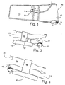
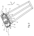
- a vibratory massage device 10 in accordance with the present invention comprises a drive unit 12.
- the drive unit comprises a casing 14 housing an electric low voltage DC motor 16 mounted in the casing through flexible mountings 18,20.
- the motor drives an eccentric weight 22 mounted on a fan 23 on each end of an armature 24.
- On rotation of the armature 24 motor 16 imparts a vibration in the casing 14 in a radial plane (x,y) with respect to the armature 24.
- the mountings 18,20 are soft, a component of the vibration occurs in a direction orthogonal (z) to the radial plane. Consequently, the vibration of the casing in response to the vibration of the motor is three-dimensional.
- a frame 27 To the casing is fixed, by screws 29 (see Figure 6 ) retained in apertures 25 of the casing, a frame 27. On the frame is disposed fabric cushioning to form a pad 110. The cushioning covers the drive unit 12 with a sleeve 40.
- the motor is adapted to rotate at about 2400 rpm providing a frequency of vibration of about 40 Hz.
- the amplitude of vibration in each direction may be different and between about 0.1 mm and 0.5 mm.
- a speed control arrangement 90 is provided (see Figure 7 ), conveniently disposed in a separate hand unit (not shown).
- Arrangement 90 controls the power supplied to the motor, and is connected to AC mains voltage 92, which typically is between 50-60 Hz.
- the mains supply is connected to a double bobbin isolation transformer T having a nominal 24volt AC output. That supply is fed to a switch/rectifier 94, which in turn provides power to the motor 16 along cable 32.
- a detector 96 detects the output of the transformer T and activates the switch 94 to commence supply of current to the motor 16 when the voltage is zero; that is to say, at each zero crossing of the supply voltage.
- the detector 96 activates a timer 98 to commence counting, the output of which counter is supplied to a comparator 100.
- the comparator 100 is also supplied with the value of a number stored in a memory 102 and, when the count of the counter 98 reaches the number stored in the memory 102, the comparator activates the switch 94 to interrupt supply of current to the motor 16.
- the memory is provided with means 104 by which the number stored can be changed, so that the speed of the motor can be varied. Conveniently, it is found that the counter should count at a rate of about 25 KHz giving about 250 steps in each half cycle.
- the pad 110 is about 400 mm long and about 250 mm wide at the motor end and about 200 mm wide at its other end.
- a patient suffering from a leg ulcer lays the affected leg 29 longitudinally along the pad.
- the motor is at the heel end 31 of the leg, as shown in Figure 3 , or is under the knee 33, as shown in Figure 4 , is a matter of patient choice.
- the former arrangement may be preferable, whereas if it is on the calf or higher, the latter arrangement may provide more direct delivery of vibrations to the site and environment of the ulcer.
- Pressure applying means in the form of a strap 46 is employed to press the leg into close contact with the pad 110, although any means will do, such as a weight.
- the strap 46 conveniently is separate from the pad and comprises a band of material having hooped nylon on one surface and hooked nylon on the other. When its ends are overlapped and pressed together after wrapping around the patient's leg and pad, the strap secures the pad to the patient's leg.
- the strap is about 100 mm wide.
- Table 1 shows the results of preliminary trials conducted on patients suffering long term problems with ulcers.
- the patient arranged a device 10 in accordance with the present invention as shown in Figures 3 or 4 with a strap 46 comfortably, but firmly, pressing the pad 110 against the patient's leg.
- Light Reflective Rheography is a non-invasive tool to measure the venous refill in the lower leg.
- the patient sits on a chair with the heel on the floor.
- An infrared probe is attached by an adhesive disc 10 cm above the medial malleoli.
- the patient then performs 10 ankle dorsiflexions to empty the veins, keeping still whilst the veins refill.
- a graph is recorded giving the time in seconds for how long it takes to refill the vein. 25 seconds and above would show a normal refilling time, below would indicate venous disease.
- Ulcer history was recorded of duration and compression used, and a written consent obtained. A trial wearing the Setopress compression bandaging was undertaken to establish degree of comfort and wear time.
- the leg was washed in warm tap water, dried and moisturised with 50% White Soft Paraffin and 50% Liquid Paraffin (50/50) to hydrate the skin.
- a non-adherent dressing (NA®) was used as a primary dressing with a pad to absorb exudate.
- Tubifast® - a cotton tubular bandage - was applied to the lower leg to protect the skin.
- Softban® - a cotton wool bandage - was applied from the base of the toes to the tibial tuberosity to protect the malleolus and tibial crest, followed by the Setopress® compression bandage.
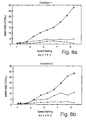
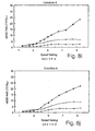
- FIG. 8 to 11 illustrate graphically the vibration regime established by the pad under the conditions shown in Table V below.
- Table V Condition Subject Motor at Support Strap Measured at 1 A Knee Free Tight Middle 2 A Knee Firm Tight Middle 2A A Knee Soft Tight Middle 3 A Knee Soft Tight Motor end 4 A Knee Soft Loose Middle 5 A Heel Soft Tight Middle 6 A Heel Soft Tight Other end 7 A Heel Firm Tight Middle 8 B Heel Firm Tight Middle 9 B Heel Soft Tight Middle
- condition 4 has the strap loose. It can' be seen that at a speed setting between 4 and 5 the components in the y and z directions are much nearer the value in the x direction when the strap is tight than when it is loose.
- a cover 150 comprising a pouch 152 of an impervious material such as plastics or nylon.
- impervious should be understood to mean that liquid weeping from a bandaged ulcer of a patient undergoing treatment with the device will not, on the whole, penetrate the material and contaminate the pad.
- the cover may not be utterly impervious and therefore on occasions some contamination could occur if significant leakage occurs.
- the pouch has a front 154 and a back 156, and two sides 158, 160.
- the pouch 152 has a top lip 162 and, on the rear side 156 of the pouch a flap 164 depends from the lip 162.
- a strip 166 of hooped nylon material is located at the end of the flap.
- a strip 166 of hooped nylon material is located on the front face 154 of the pouch, near the lip 162, a strip of hooked nylon 168.
- the pouch 154 is shaped to snugly receive the pad 110 of a massage device 10 of the type shown in Figures 1 to 6 .
- the motor 12 is not received in the pouch 154.
- the flap 164 covers the motor when the flap is folded over and the first and second fasteners formed by the strips 166, 168 are inter-engaged.
- the flap defines, with the lip 162 at the sides 158, 160, two openings 170, 172 through which the ends of the drive unit 12 project.
- the drive unit 12 has cooling slots 174 through which air is drawn to cool the motor 16 by the fans 23. This flow is therefore not impeded by the cover 152.
- the cover 150 has two straps 46a, b sewn into the join 155 between the front rear faces 154, 156 (indeed, the pouch is conveniently formed by sewing a blank as shown in Figure 12c along edges 155a, b after folding along line 157 forming the bottom end of the pouch).
- the straps 46a, b have strips 176 of hooped nylon at their ends.
- On the other side 160 of the pouch is provided a long strip 178 of hooked nylon.
- the strips 176, 178 form third and fourth fasteners and when a patient's leg is placed along the pad 110 (front face 154 of cover 150) the leg can be pressed against the device 10 by folding over the straps 46a, b and engaging the fasteners 176, 178.
- the elongate strip 178 permits longitudinal adjustment of the attachment of the straps. Indeed, one strap could be omitted altogether without detracting from the benefits of the invention.
- the strips 176 are somewhat elongate in order to accommodate different dimensions of different patient's legs.
- FIG 13 illustrates an alternative embodiment of a cover. Any cover that serves the purpose of protecting the pad from contamination has its place, but Figures 12 and 13 illustrate novel covers.
- Cover 150' comprises a simple sheet 182 of material that is impervious to liquid weeping form ulcers.
- the sheet has a hem 180 incorporating a tie string (not shown) which can gather the edges of the sheet on the underside 110b of the pad 110.
- the cover is drawn taught over the top, that is to say, operative, side 110a of the pad 110.
- Alternative tightening arrangements are quite feasible, for example, several draw strings could be provided at the corners and sides of the sheet 150'to be tied together across underside 110b of the pad 110.
- a strap 46c could be integrated with the cover 150', as described above with reference to Figure 12 , or be separate, as shown in Figure 13 .
- two strips 178a,b of hooked material are provided along the sides of the sheet 150, while the strap 46c either comprises, or is covered with, hooped material. Then, when the cover is on the pad, and a patient's limb is resting on the top side 110a of the pad 100, the strap 46c can be applied anywhere along the length of strip 178a (for example) of the cover 150', passed over the patient's limb and fastened to the strip 178b.
- the possibility of variation of the positioning of the strap with respect to the patient's limb is an important comfort feature.
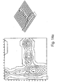
- FIGS 14a to h illustrate the results of pressure measurements employing a pressure mat disposed between the leg of a subject and the pad of a vibratory massage device in accordance with the present invention.
- the mat measures pressure in mmHg over its area, and so as to provide a contour map of pressure.
- Figures 14f to h the subject's leg is strapped to the pad to a level which is comfortable for the subject. Indeed, the primary observation to be made is that the strapping is decidedly not tight and does not, of itself, greatly increase to any significant degree the level of pressure applied. This is evident from a comparison of Figures 14a and e in which the maximum pressure recorded in each case is about the same. Figure 14e is likewise with no massage being effected, but Figures 14f, g and h are equivalent to Figures 14b, c and d in being set at massage levels 3, 4 and 5 respectively.
- each of Figures 14a to h also depict a relief image of the same information shown in the corresponding contour map.
Landscapes
- Health & Medical Sciences (AREA)
- Epidemiology (AREA)
- Pain & Pain Management (AREA)
- Physical Education & Sports Medicine (AREA)
- Rehabilitation Therapy (AREA)
- Life Sciences & Earth Sciences (AREA)
- Animal Behavior & Ethology (AREA)
- General Health & Medical Sciences (AREA)
- Public Health (AREA)
- Veterinary Medicine (AREA)
- Percussion Or Vibration Massage (AREA)
Description
- The present invention relates to a vibratory massage device for the treatment of open sore ulcers, lymphoedema and deep vein thrombosis (DVT) as they affect the human or animal body.
- It is well understood that three-dimensional vibration (referred to as cycloidal vibration) has beneficial effects in improving blood circulation, joint mobility, and respiratory conditions, and relieving tension. Such vibration is in the frequency range of 15 to 75 Hz with an amplitude varying between 0.1 and 0.5 mm, depending on the orthogonal direction.
- Decubitus ulcers are caused by continuous pressure at specific points of the body when a patient is immobile for extended periods of time. It is known that vibration can assist in preventing the development of such sores and
US-A-5606754 suggests a bed which has vibration means to reduce the incidence of bed sores. - Ulcers are caused by underlying blood circulatory problems, either venous or arterial disease. If the venous system in the leg fails to work normally, the pressure in the leg veins rises. This reduces circulation in the lower leg and leads to swelling and discomfort. The skin changes and becomes vulnerable and is poor at healing. A small injury, bite or minor infection, that would normally heal quickly, instead progresses and an area of skin break down results in the formation of an ulcer. Varicose veins, a previous deep vein thrombosis, or primary failure of the valves in the veins can all contribute to ulcers.
- The current method of treatment is to cover the affected skin area with a dressing, in order to keep the skin moist and prevent infection from entering the sore, and to immobilise the sore in order to facilitate healing. However, some patients suffer from venous ulcers for extended periods of time in the order of months or even years before they heal, if ever. There is an evident need for more efficient treatment of ulcers.
-
US-A-5948009 discloses an ablation electrode for treating canker sore in which vibratory massage is applied to create a lesion. This is said to create the conditions for subsequent healing. - Lymphoedema is the chronic swelling of subcutaneous tissues due to the accumulation of excessive lymph fluid. The accumulation of lymph fluid results from impairment to the normal clearing function of the lymphatic system and/or from an excessive production of lymph. Lymphoedema is divided into two broad classes according to aetiology. Primary lymphoedema is a relatively uncommon, chronic condition which may be due to such causes as Milroy's Disease or congenital anomalies. Secondary lymphoedema, which is much more common, results from the destruction of, or damage to, formerly functioning lymphatic channels, such as surgical removal of lymph nodes or post radiation fibrosis, among other causes.
- Current common treatments include manual lymphatic drainage (a form of skin massage), exercise program and a form of compression bandaging. However, pneumatic compression therapy is also used, although proof of its effectiveness is lacking. Indeed, care needs to be taken to avoid forcing fluid too rapidly from the limb to adjacent parts of the body.
- Deep Vein Thrombosis (DVT) refers to the formation of a thrombus (blood clot) within a deep vein, commonly in the thigh or calf. The blood clot can either partially or completely block the flow of blood in the vein.
- Compression therapy is used to aid circulation to prevent patients at risk of clotting from developing DVT. Likewise, pneumatic compression therapy is used on patients at risk of DVT and this treatment is often used prior too and after surgery, especially limb surgery such as knee surgery and joint replacement where the risk of DVT is often greater.
- P Lievens, A Leduc and J Dewald presented a paper under the title "The Use of Cycloidal Vibrations Therapy on Blood and Lymph Circulation and on Wound Healing", at the VII International Congress of Lymphology, Firenze, Italy 28 October to 2 November 1979. In that there was a suggestion that some aspects of wound healing in test mice were improved by a regime of cycloidal vibrations. However, nothing has come of that work and its teaching is limited.
- Also, AJ Pickup, S Alexander, and RG Gosling presented a paper under the title "The effect of cycloid vibration on leg blood flow and ulcer pain" to the Section of Dermatology of the Royal Society of Medicine in 1978. while vibration was recognised to dramatically reduce pain from leg ulcers, only a slight improvement in healing was noticed.
- It is an object of the present invention to provide an improved device for treatment of ulcers, and also lymphoedema and deep vein thrombosis.
-
GB-A-2096899 - In accordance with the present invention there is provided an ulcer, lymphoedema and deep vein thrombosis treatment device comprising a device as disclosed in
GB-A-2096899 - Indeed, preferably, the area over which a given level of pressure in excess of 1333 Pa (10 mmHg), preferably 2666 Pa (20 mmHg), is applied to the limb by the pad is increased by at least 25%, preferably 50%, by application of said pressure applying means.
- Preferably, the drive unit is substantially cylindrical. It may have a casing mounting a motor having an armature parallel the axis of the cylinder. The motor may drive an eccentrically mounted weight to provide oscillations of the casing in a radial plane. The motor may be mounted through flexible mountings in the casing so that a component of the vibration is created in an axial direction of the armature.
-
GB-A-2096899 - Preferably, therefore, the motor is electrically powered from mains AC electricity, the drive unit including digital control means to ensure smooth supply of energy to the motor.
- Said digital control means preferably comprises:
- a detector for each zero crossing point of the AC power supply and adapted to disconnect power from the motor when said crossing point is detected;
- a timer comprising a counter started by said detector;
- a comparator to compare the count of said counter with a number stored in a memory and to switch power to the motor when said count equals said number.
- Preferably, a low voltage transformer is disposed between the power supply and detector. A rectifier may convert the power supply to the motor to DC, if the motor is a DC motor.
- Preferably said number is adjustable to vary the power supplied to the motor, and hence its speed of rotation and hence said frequency.
- Preferably said counter is capable of providing about 250 counts in each half cycle of the power supply.
- Preferably the drive unit operates at a frequency of between 30 and 60 Hz.
- Said pad preferably comprises a rigid frame connected to said drive unit and through which mechanic vibrations are transmitted, and cushioning overlying the frame.
- The device is useful in a method of treatment of ulcers of the human or animal body, which method comprises the step of subjecting the body in the area of the ulcer to mechanical vibrations for an effective period of time, said vibrations having a frequency of between 15 and 75 Hz, and an amplitude of between 0.1 and 0.5 mm.
- The device is also useful in a method of treatment of lymphoedema of a patient, which method comprises the step of subjecting the body in the area of the lymphoedema to mechanical vibrations for an effective period of time, said vibrations having a frequency of between 15 and 75 Hz, and an amplitude of between 0.1 and 0.5 mm.
- Furthermore, the device is also useful in a method of prophylactic treatment of deep vein thrombosis, which method comprises the step of subjecting the body in the area of the thrombosis to mechanical vibrations for an effective period of time, said vibrations having a frequency of between 15 and 75 Hz, and an amplitude of between 0.1 and 0.5 mm.
- Said vibrations, when provided by the device of the present invention have, in each case, components in three orthogonal directions, said frequency being the same or different in each direction, and said amplitude being the same or different in each direction. Preferably said period is more than fifteen minutes, ideally about thirty minutes. The treatment is preferably repeated three times a day.
- Preferably, said treatment is applied by a vibratory device comprising a pad, and said method also involves the application of pressure by the pad against the tissue of the patient. The pad is preferably a cushioned frame fixed to a vibratory drive unit.
- When the method above employs the device provided by the present invention, the pad is applied by said pressure applying means to the leg of a patient suffering from ulcers, lymphoedema or deep vein thrombosis and so that, in use, the device delivers vibrations in the leg of the patient at a frequency of between 20 and 50 Hz, and with an RM.S acceleration in the axial direction of the tibial bone of between 5 and 15 ms-2, and in a radial plane with respect to the tibial bone with an RMS acceleration of between 2 and 5 ms-2.
- Preferably, the device delivers vibrations in the leg of the patient at a frequency of about 30 Hz, and with an RMS acceleration, in the axial direction of the tibial bone, of about 10 ms-2, and, in a radial plane with respect to the tibial bone, with an RMS acceleration of between 2 and 5 ms-2.
- Despite the apparent contrary indication that movement will unsettle the healing of venous ulcers, it has been discovered that cycloid vibrations have a beneficial effect on their healing, and that this healing is dramatically improved by the application of pressure against the tissue of the patient by the cushioned pad that is delivering the vibrations. Without being reliant on any particular theory, this beneficial effect may be due to improved blood circulation caused by the vibrations and increased moisture in the upper dermis and epidermis. Indeed, the healing effects of the present invention are especially felt when two features of the invention are fully exploited. The first is the three-dimensional aspect of the vibration; some benefit is experienced with two-dimensional vibration but significantly enhanced effects have been noted with three-dimensional "cycloidal" vibration, particularly when employing the motor control described above which provides smooth power delivery to the motor. The second is the pressure applying means, which serves to unite the patient's limb with the device and ensures deep transmission of the vibrations into the flesh of the patient. This is particularly the case given the cushioned pad, which of course tends to dampen vibration. By pressing the pad against the patient's leg, the area of contact is increased and this enhances the transmission of vibration throughout a greater volume of the patient's tissue. Together with effective motor control limiting the appearance of transient spikes and the pressure applying means spreading the application of the vibrations, more intense vibrational treatment is possible without exceeding the comfort threshold that patients encounter as the intensity of vibration is increased.
- Said cover may comprise an open pouch to receive said pad and drive unit, fastening means to close the pouch about the pad and drive unit, openings in the cover being provided to permit cooling airflow into the drive unit.
- Said cover preferably comprises a deep pouch to receive the pad, and a flap on a front side of the pouch extending from the lip thereof and having a first fastener along its edge remote from said front lip and adapted to detachably fasten to a second fastener along the lip of the pouch on its rear side, two of said openings thereby being defined between each free edge of the flap and the lip of the pouch between its front and rear sides respectively.
- Preferably, one of said fasteners comprises a strip of hooked material while the other comprises a strip of hooped material, so that pressing said materials together effects a releasable connection.
- Preferably, the cover is of impervious material to prevent liquid from penetrating and contaminating a pad received within the cover.
- Preferably, a strap is integrally formed in the cover. Indeed, there may be two straps spaced along the pouch so that, if one is in the area of the ulcer of the patient when the patient's limb is located appropriately with respect to the pad, it can be left undone. When the other strap is secured, this applies sufficient pressure to provide the improved vibration transmission.
- Preferably, the or each strap is sewn at one end into a side edge of the pouch and at its other end is provided with a third fastener, the other side edge of the pouch being provided with a complimentary fourth fastener.
- Preferably, the fourth fastener extends along the length of the pouch to vary the possible disposition of the or each strap when the third and fourth fasteners are engaged.
- The third and fourth fasteners may comprise hooped and hooked fabric material. Indeed, the fourth fastener may comprises a strip of such material along a significant part of the length of the side edge of the pouch so that the or each strap can vary in its position of attachment to the other side of the cover.
- The cover serves to protect the pad from contamination from weeping and ulcers. Such weeping tends to occur when they are treated in accordance with the present invention.
- In another aspect, the cover may comprise a simple sheet of material having means to gather its edges on an underside of the pad of the vibratory device, and render the sheet taught on an operative side of the pad against which a patient's limb is intended to lie. At least one hole is preferably provided in the sheet to permit the drive unit to protrude through.
- The cover may comprise means to fasten a strap to the cover, and hence to the pad, for the purpose of providing said pressure applying means. Said strap fastening means may comprise strips of hooked or hooped material along the sides of the cover to which a strap of respectively hooped or hooked material may be fastened.
- The invention is further described hereinafter, by way of example, with reference to the accompanying drawings, in which:-
-
Figure 1 is a perspective view of a vibratory massage device in accordance with the present invention, (having attached thereto a transducer pack analysing the vibrations of the pad in three orthogonal directions x, y and z); -
Figure 2 is an assembly drawing of a drive unit and frame of the device ofFigure 1 ; -
Figure 3 is a side view of the device ofFigure 1 strapped to a patient's leg with the drive unit at the heel of the patient; -
Figure 4 is a similar view toFigure 3 , but with the drive unit under the knee of the patient; -
Figure 5 is a perspective view of the device ofFigure 1 , with the casing open; -
Figure 6 is a top view of the drive unit with the casing open; -
Figure 7 is a schematic representation of the control function of the motor of the drive unit; -
Figures 8 a to j are graphs of RMS acceleration of the vibrations produced under varying conditions in the three orthogonal directions x, y and z, as well as the frequency of the vibrations; -
Figures 9a and b are respectively graphs of acceleration in each direction plotted against time, and a frequency range plot in each direction, both at a preferred speed of operation; -
Figures 10a and b are asFigure 9 , but at a higher speed; -
Figures 11a, b and c show the frequency of operation for different conditions of operation against speed setting of the device; -
Figures 12a, b and c show a cover for use with the pad of the present invention: in perspective view; in perspective view again but with a device inside; and in plan as a blank before assembly; -
Figure 13 shows in perspective another form of cover ; and -
Figures 14a to h illustrate a contour map of pressure between the leg of a subject and a vibratory massage device according to the present invention, each in different circumstances. - In the drawings, a
vibratory massage device 10 in accordance with the present invention comprises adrive unit 12. The drive unit comprises acasing 14 housing an electric lowvoltage DC motor 16 mounted in the casing throughflexible mountings eccentric weight 22 mounted on afan 23 on each end of anarmature 24. On rotation of thearmature 24motor 16 imparts a vibration in thecasing 14 in a radial plane (x,y) with respect to thearmature 24. Because themountings - To the casing is fixed, by screws 29 (see
Figure 6 ) retained inapertures 25 of the casing, aframe 27. On the frame is disposed fabric cushioning to form apad 110. The cushioning covers thedrive unit 12 with asleeve 40. - The motor is adapted to rotate at about 2400 rpm providing a frequency of vibration of about 40 Hz. Depending on various factors (primarily connected with the degree of restraint placed upon the device by its location on the limb of an animal) the amplitude of vibration in each direction may be different and between about 0.1 mm and 0.5 mm.
- However, a
speed control arrangement 90 is provided (seeFigure 7 ), conveniently disposed in a separate hand unit (not shown).Arrangement 90 controls the power supplied to the motor, and is connected toAC mains voltage 92, which typically is between 50-60 Hz. The mains supply is connected to a double bobbin isolation transformer T having a nominal 24volt AC output. That supply is fed to a switch/rectifier 94, which in turn provides power to themotor 16 alongcable 32. - However, a
detector 96 detects the output of the transformer T and activates theswitch 94 to commence supply of current to themotor 16 when the voltage is zero; that is to say, at each zero crossing of the supply voltage. - At the same time, the
detector 96 activates atimer 98 to commence counting, the output of which counter is supplied to acomparator 100. Thecomparator 100 is also supplied with the value of a number stored in amemory 102 and, when the count of thecounter 98 reaches the number stored in thememory 102, the comparator activates theswitch 94 to interrupt supply of current to themotor 16. - The memory is provided with means 104 by which the number stored can be changed, so that the speed of the motor can be varied. Conveniently, it is found that the counter should count at a rate of about 25 KHz giving about 250 steps in each half cycle.
- Because the
frame 27 is rigidly fixed to thecasing 14 of thedrive unit 12, vibrations of thedrive unit 12 are therefore transmitted to thepad 110. The pad is about 400 mm long and about 250 mm wide at the motor end and about 200 mm wide at its other end. - In use, a patient suffering from a leg ulcer lays the
affected leg 29 longitudinally along the pad. Whether the motor is at theheel end 31 of the leg, as shown inFigure 3 , or is under theknee 33, as shown inFigure 4 , is a matter of patient choice. However, if an ulcer is on the patient's ankle or lower leg, the former arrangement may be preferable, whereas if it is on the calf or higher, the latter arrangement may provide more direct delivery of vibrations to the site and environment of the ulcer. - Pressure applying means in the form of a
strap 46 is employed to press the leg into close contact with thepad 110, although any means will do, such as a weight. Thestrap 46 conveniently is separate from the pad and comprises a band of material having hooped nylon on one surface and hooked nylon on the other. When its ends are overlapped and pressed together after wrapping around the patient's leg and pad, the strap secures the pad to the patient's leg. The strap is about 100 mm wide. - In any event, Table 1 shows the results of preliminary trials conducted on patients suffering long term problems with ulcers. In each case, the patient arranged a
device 10 in accordance with the present invention as shown inFigures 3 or 4 with astrap 46 comfortably, but firmly, pressing thepad 110 against the patient's leg. - The motor control was switched to setting 5 and vibration was effected for about thirty
minutes 3 times per day. The results of these treatments are shown in Table I below. - In each case the conventional treatment regime was maintained, along side the vibration treatment. This comprised keeping ulcers dressed with multi-layer pressure bandages to reduce the potential for infection. Dressings were changed weekly.
Table I Patient Age and Sex Age of Ulcer Weeks Position of Ulcer Vibration treatment (Weeks) Reduced Swelling Y/N Pain * Reduction Start/End Improved Mobility Y/N Condition of Ulcer after treatment 84M 100 Ankle 9 Y ** 0/0 Reduced Size 84F 6 Above ankle 6 Y 2/0.5 (no pain at nights Scab in 3 weeks, healed in 6 weeks 73M 17 Ankle 10 Y 2/less 60% healed 85F 39 Above ankle 10 N 5/1 Reducing slowly 86F 17 Above ankle 5 Y 1/0 @ week 4HEALED 73M 17 Small ulcers 5 N 1/0 @ week 2HEALED 54M 75 Ankle 2 Y (after 4 days) 0/0 Improvement after 4 days 73M 200 Ankle 2 Y 2.5/1.5 Improving 90M 50 Ankle 2 Minimal 3.5/2.5 Healing * Pain is on scale 0 to 5 where 0 is no pain and 5 is intense pain
** Temporary increase in swelling atweek 5 but reduced overall - As can be seen from Table I above, the response of patients, even those afflicted with long term ulcers that had hitherto failed to respond to conventional methods of treatment, was in all cases favourable with healing to a greater or lesser extent being effected in each case.
- A further study of ulcerated patients has been conducted. This study proposed to combine the two therapies of compression bandaging and cyclodial vibration to determine whether this would enhance the healing of venous leg ulceration. 18 patients with venous ulceration were offered a 12 week trial. The vibration device was used times daily for 30 minutes at home, with twice weekly dressings using a non adherent dressing and a Setopress® compression bandage. 10 patients healed within 12 weeks and the remaining 8 patients completed the 12 week study with 31% to 90% reduction in ulcer size. Quality of life assessments showed a reduction of pain in 13 out of the 18 patients. 10 had some reduction of exudate. Ultrasound measurements showed reduced fluid content in the upper dermis in patients that had healed and in ulcers that were improving.
- Prior to commencing the study, the patients were invited to a Leg Ulcer Clinic for a screening visit. This visit was designed to put the patient at ease and to promote rapport with their research nurse. Doppler ultrasound and Light Reflective Rheography were used to measure Ankle Brachial Pressure index and venous refilling time.
- Light Reflective Rheography is a non-invasive tool to measure the venous refill in the lower leg. The patient sits on a chair with the heel on the floor. An infrared probe is attached by an
adhesive disc 10 cm above the medial malleoli. The patient then performs 10 ankle dorsiflexions to empty the veins, keeping still whilst the veins refill. A graph is recorded giving the time in seconds for how long it takes to refill the vein. 25 seconds and above would show a normal refilling time, below would indicate venous disease. - Patients were given the opportunity to try a vibration device in accordance with the present invention. Patients were advised to use the device on their bed at home to promote venous drainage.
- Ulcer history was recorded of duration and compression used, and a written consent obtained. A trial wearing the Setopress compression bandaging was undertaken to establish degree of comfort and wear time.
- Following enrolment to the study, patients attended the Clinic twice weekly for dressing changes, or the research nurse visited the patient at home.
- At each dressing change the leg was washed in warm tap water, dried and moisturised with 50% White Soft Paraffin and 50% Liquid Paraffin (50/50) to hydrate the skin. A non-adherent dressing (NA®) was used as a primary dressing with a pad to absorb exudate. Tubifast® - a cotton tubular bandage - was applied to the lower leg to protect the skin. Softban® - a cotton wool bandage - was applied from the base of the toes to the tibial tuberosity to protect the malleolus and tibial crest, followed by the Setopress® compression bandage.
- The following assessments were undertaken weekly.
- Ulcer area using planimetry and photography.
- Computer analysis of circumferential leg volume measurement at 4 cm intervals from malleolus to tibial tuberosity.
- Quality of life assessment (pain/exudate/odour)
Pain assessment was established by a visual analog scale from 1-5. (None, mild, uncomfortable, horrible or excruciating).
Exudate was established by the amount of strike through of the NA, pad or bandage on a scale of none, mild moderate or heavy.
Odour was qualitatively assessed nasally by the patient and the research nurse on the scale of none, mild, moderate or offensive. - Dermascan® Ultrasound scans were taken at 4 weekly intervals to establish tissue hydration and dermal structure of both lower legs. The non-study leg was used as a control. Predetermined areas at three points of each leg - lower (ankle), middle (calf) and upper (below knee) were documented at the first scan to ensure that the same area was successively scanned.
- 18 patients either completed the 12 weeks or healed with a healing rate of 55.5%. 10 patients healed with a mean healing time of 7.2 weeks (range: 4-12 weeks). Their average ulcer size at the start of the trial was 3.71cm (range 1.5cm2 - 7.0cm2), and they had a mean duration 9.35 months (range 1.5 - 24 months). Of the 8 patients that completed the 12 week study, 3 patients had ulcers greater than 10cm2, with a reduction of ulcer size of 63 - 65%. Average ulcer size for them at the start of study was 18.25cm2 (range 13.5cm2 - 28.75cm2), with a mean duration of 29 months (range 4 - 48 months). Finally, the 5 patients with ulcer size less than 10cm2 (range 2 - 9cm2) had a mean reduction in size of 50% at the end of the trial. Their initial mean size was 6.55cm2 (range 2 - 9cm2) and duration of 8 months (range 2 - 24 months). More detail can be seen in Tables II, III and IVa and b below.
- Quality of life assessments showed a reduction of pain in 13 patients and reduction of exudate in 10. 12 patients experienced no ulcer odour during the treatment, 1 patient ulcer odour resolved at 3 weeks. The remaining 5 patients had ulcer odour that fluctuated between none, mild or moderate.
- Computer analysis of the patients circumferential volume measurements of the lower leg showed a 1% - 15% reduction in fluid volume.
Table II Patient Demographics Gender: 5 males/13 females Range Mean Patient Age: 51-93 years 74 years Ulcer duration: 1.5-48 months 12.3 months Initial ulcer size: 0.75cm2-28.75cm2 8.5cm2 Table III Data results Healed (10=55.5%) Range Mean Ulcer duration: 1.5-24 months 9.35 months Initial ulcer size: 0.75cm2-7cm2 4cm2 Healing time: 4-12 weeks 7.2 weeks % of volume reduction 1-8% 4% Improved but not healed - 3 patients > 10cm2 4-48 months 29 months Ulcer duration: 13.5 - 28.75 cm2 18.25cm2 Initial ulcer size: 63-65% 64% % ulcer size reduction: 2-15% 8.00% % of volume reduction: Improved but not healed - 5 2-24 months 6 months patients < 10cm2 2-9cm2 6.55cm2 Ulcer duration: 31-90% 50% Initial ulcer size: 4-10% 8% % ulcer size reduction: % of volume reduction: Table IVa Ulcers < 10cm 2 at Start Pat. No. Age Duration Start Size End Size Weeks % Reduction (months) (cm2) (cm2) (cm2) 1 86 24 9 6.25 12 31 2 84 1.5 7 6 100 4 85 3 8.5 5.25 12 38 5 9 5 8 5 100 6 73 4 2.25 5 100 18 78 10 4.25 9 100 19 55 3 1.5 4 100 22 74 8 8 2.75 12 48 25 74 8 8 4.5 12 44 26 75 3 6.75 4 100 28 74 48 3 9 100 30 56 4 2 12 100 32 72 10 0.75 12 100 33 59 2 2 0.1 12 90 34 51 6 2.6 8 100 Totals: 133.5 69.85 Mean: 8.9 4.66 83.40% Table IVb Ulcers > 10 (cm2) at Start Pat. No. Age Duration Start Size End Size Weeks % reduction (months) (months) (cm2) (cm2) 3 74 4 13.5 4.8 12 64 13 93 36 12.25 4.5 12 63 31 83 48 28.75 10 12 65 Totals: 88 54.75 Mean: 29 18.25 64 - Turning now to
Figures 8 to 11 , these illustrate graphically the vibration regime established by the pad under the conditions shown in Table V below.Table V Condition Subject Motor at Support Strap Measured at 1 A Knee Free Tight Middle 2 A Knee Firm Tight Middle 2A A Knee Soft Tight Middle 3 A Knee Soft Tight Motor end 4 A Knee Soft Loose Middle 5 A Heel Soft Tight Middle 6 A Heel Soft Tight Other end 7 A Heel Firm Tight Middle 8 B Heel Firm Tight Middle 9 B Heel Soft Tight Middle - The same subject person (A) was used in most tests. The position of the motor was varied between under the "Knee" (
Figure 4 arrangement) or at the "Heel" (Figure 3 arrangement). The leg with the pad attached was either "Free" (not shown), supported on a "Firm" base, or supported on a "Soft"cushion 37. Thestrap 46 was either "Tight" or, in one case, "Loose". Measurements of accelerations were made using accelerometer transducers positioned to measure in each of the three axes x, y and z. The transducers (not shown) were disposed on a base 35 (seeFigure 1 ) between thepad 110 and the subject'sleg 29. The base was either in the "Middle" of the pad, at the "Motor end" thereof, or it's "Other end". The use of quotation marks is merely a reference to the same terms used in Table II above. - Referring first to
Figures 11a, b and c , in most conditions, the frequency of operation was consistently proportional to speed setting. However, when a particularly rigid connection is achieved (seeconditions - Referring to
Figures 8a to j , it can be seen that, with increasing speed, the acceleration in the x direction, which is in the longitudinal direction with respect to the subject's leg, increases exponentially. On the other hand, in the y and z directions, the increase is more proportional and in some cases not especially apparent. It is suspected that it is partly for this reason that it is found in practice that a speed setting between 4 and 5 appears to be the optimal treatment speed. Indeed, in some conditions, the z component of acceleration almost disappears at higher speeds, leaving essentially just one dimension (x) to the vibration, with a minor component in the y direction. - However, at speed setting 5 or thereabouts, the vibration is quite evenly three dimensional. This is particularly the case with the strap in place.
Conditions condition 4 has the strap loose. It can' be seen that at a speed setting between 4 and 5 the components in the y and z directions are much nearer the value in the x direction when the strap is tight than when it is loose. - In
Figures 9a , the actual acceleration in each direction is plotted against time so that, for example, over about 0.1 seconds 2.5 acceleration cycles occur. This equates to a frequency of about 25 Hz, the amplitude of the accelerations being greatest in the x direction and least in the z direction. InFigure 9 , the speed setting is 4.5, whereas inFigure 10 it is 9.5, so that about six acceleration cycles of substantially greater amplitude occur in the measurement period. This equates with a frequency of about 60 Hz. - In both
Figures 9b and10b , the frequency range is plotted against the acceleration at each frequency and it can be seen that there is only one spike of any significance in each direction at both speed levels. - Turning to
Figures 12a, b and c , acover 150 is illustrated comprising apouch 152 of an impervious material such as plastics or nylon. In the context of the present invention, "impervious" should be understood to mean that liquid weeping from a bandaged ulcer of a patient undergoing treatment with the device will not, on the whole, penetrate the material and contaminate the pad. However, for the purposes of patient comfort, the cover may not be utterly impervious and therefore on occasions some contamination could occur if significant leakage occurs. - The pouch has a front 154 and a back 156, and two
sides pouch 152 has atop lip 162 and, on therear side 156 of the pouch aflap 164 depends from thelip 162. - At the end of the flap is a
strip 166 of hooped nylon material. On thefront face 154 of the pouch, near thelip 162, is a strip ofhooked nylon 168. - The
pouch 154 is shaped to snugly receive thepad 110 of amassage device 10 of the type shown inFigures 1 to 6 . Themotor 12 is not received in thepouch 154. Instead, theflap 164 covers the motor when the flap is folded over and the first and second fasteners formed by thestrips lip 162 at thesides openings drive unit 12 project. Thedrive unit 12 has coolingslots 174 through which air is drawn to cool themotor 16 by thefans 23. This flow is therefore not impeded by thecover 152. - The
cover 150 has twostraps 46a, b sewn into thejoin 155 between the front rear faces 154, 156 (indeed, the pouch is conveniently formed by sewing a blank as shown inFigure 12c alongedges 155a, b after folding alongline 157 forming the bottom end of the pouch). Thestraps 46a, b havestrips 176 of hooped nylon at their ends. On theother side 160 of the pouch is provided along strip 178 of hooked nylon. Thestrips front face 154 of cover 150) the leg can be pressed against thedevice 10 by folding over thestraps 46a, b and engaging thefasteners - Should either strap tend to apply pressure to an ulcer on the patient's leg, the
elongate strip 178 permits longitudinal adjustment of the attachment of the straps. Indeed, one strap could be omitted altogether without detracting from the benefits of the invention. - The
strips 176 are somewhat elongate in order to accommodate different dimensions of different patient's legs. -
Figure 13 illustrates an alternative embodiment of a cover. Any cover that serves the purpose of protecting the pad from contamination has its place, butFigures 12 and13 illustrate novel covers. Cover 150' comprises asimple sheet 182 of material that is impervious to liquid weeping form ulcers. The sheet has ahem 180 incorporating a tie string (not shown) which can gather the edges of the sheet on theunderside 110b of thepad 110. The cover is drawn taught over the top, that is to say, operative,side 110a of thepad 110. Alternative tightening arrangements are quite feasible, for example, several draw strings could be provided at the corners and sides of the sheet 150'to be tied together acrossunderside 110b of thepad 110. - In any event, a
strap 46c could be integrated with the cover 150', as described above with reference toFigure 12 , or be separate, as shown inFigure 13 . In this case, twostrips 178a,b of hooked material are provided along the sides of thesheet 150, while thestrap 46c either comprises, or is covered with, hooped material. Then, when the cover is on the pad, and a patient's limb is resting on thetop side 110a of thepad 100, thestrap 46c can be applied anywhere along the length ofstrip 178a (for example) of the cover 150', passed over the patient's limb and fastened to thestrip 178b. The possibility of variation of the positioning of the strap with respect to the patient's limb is an important comfort feature. - The effect of the strap can be seen most clearly with reference to
Figures 14a to h. These illustrate the results of pressure measurements employing a pressure mat disposed between the leg of a subject and the pad of a vibratory massage device in accordance with the present invention. The mat measures pressure in mmHg over its area, and so as to provide a contour map of pressure. - In
Figures 14a to e , the subject's leg rests unstrapped (ie loosely) on the pad. The arrangement is with the motor under the knee of the subject with the calf of the subject receiving most of the pressure of the pad (at 200,Figure 14a ) and the heel also (at 202). InFigure 14a , no vibratory massage is applied, but throughFigures 14b, c and d , vibration is set atlevels - In
Figures 14f to h , the subject's leg is strapped to the pad to a level which is comfortable for the subject. Indeed, the primary observation to be made is that the strapping is decidedly not tight and does not, of itself, greatly increase to any significant degree the level of pressure applied. This is evident from a comparison ofFigures 14a and e in which the maximum pressure recorded in each case is about the same.Figure 14e is likewise with no massage being effected, butFigures 14f, g and h are equivalent toFigures 14b, c and d in being set atmassage levels - As well as a contour map of equal recorded pressures, each of
Figures 14a to h also depict a relief image of the same information shown in the corresponding contour map. - It should be noted that when vibration is applied, the pressure recorded varies with the same amplitude of the vibrations. However, the measurements presented herein are representative of the average values applied.
Table VI Strap and Condition (Figure No.) Sensors used Average Pressure (mmHg) Standard Deviation Maximum Pressure (mmHg) Area >20 mmHg pressure (units) Loose, no massage 39 11.5 6.93 30 88 (14a) Loose, massage 39 12.9 7.31 36 95 level 3 (14b) Loose, massage 39 15 8.41 32 109 level 4 (14c) Loose, massage 3g 16 8.68 37 195 level 5 (14d) Applied, no 83 11.7 9.03 31 132 massage (14e) Applied, massage 97 13.1 9.99 35 193 level 3 (14f) Applied, massage 101 13.7 11.6 39 266 level 4 (14g) Applied, massage 95 15.2 12.2 42 282 level 5 (14h) - The approximate area of the mat over which a pressure greater than 20 mmHg was recorded is given in Table VI, along with other variables recorded. From Table VI it can be seen that by applying the strap the pressure applied does not increase greatly, but the area over which it applies does, by 50% and more for a pressure of 20 mmHg in most conditions, and even more at the some level settings. The absolute level of pressure over which the increase applies is not especially the point, but it would seem to be by virtue of this increase that the effectiveness of the treatment is found to be so dramatically improved.
Claims (26)
- An ulcer, Lymphoedema and deep vein thrombosis treatment device (10) comprising:a drive unit (12) adapted to deliver mechanical vibrations at its surface in three orthogonal directions (x,y,z) at a frequency in each orthogonal direction of between 15 and 75 Hz;a pad (110) connected to said drive unit;characterised in that:the device further comprises a detachable cover (150,150'),for the pad and pressure applying means in the form of a strap (46;46a,b;46c) by means of which the pad may be secured to the limb (29) of the animal or human and by which the pad may be pressed against said limb; in that:the amplitude of vibration in each orthogonal direction is between 0.1 and 0.5 mm; and in that:said strap is integrally formed with the cover.
- A device as claimed in claim 1, in which the area over which a given level of pressure in excess of 1333 Pa (10 mmHg) is applied to the limb by the pad is increased by at least 25%, preferably 50%, by application of said pressure applying means.
- A device as claimed in claim 2, in which the area over which a given level of pressure in excess of 2666 Pa (20 mmHg) is applied to the limb by the pad is increased by at least 25%, preferably 50%, by application of said pressure applying means.
- A device as claimed in any preceding claim, in which said drive unit (12) is substantially cylindrical and in which the drive unit comprises a casing (14) mounting a motor (16) having an armature (24) parallel the axis of the cylinder.
- A device as claimed in claim 4, in which said motor drives an eccentrically mounted weight (22) to provide oscillations of the casing in a radial plane (x,y), and in which said motor is mounted through flexible mountings (18,20) in the casing so that a component of the radial oscillations is created in an axial direction (z) of the armature.
- A device as claimed in claim 4 or 5, in which the motor is electrically powered from mains AC electricity, the drive unit including digital control means (90) to ensure smooth supply of energy to the motor.
- A device as claimed in claim 6, in which said digital control means (90) comprises:a detector (96) for each zero crossing point of the AC power supply and adapted to disconnect power from the motor when said crossing point is detected;a timer (98) comprising a counter started by said detector;a comparator (100) to compare the count of said counter with a number stored in a memory and to switch power to the motor when said count equals said number.
- A device as claimed in claim 7, in which a low voltage transformer (T) is disposed between the power supply and detector.
- A device as claimed in claim 8, in which a rectifier converts the power supply to the motor to DC and the motor is a DC motor.
- A device as claimed in claim 7, 8 or 9, in which said number is adjustable to vary the power supplied to the motor, and hence its speed of rotation and hence said frequency.
- A device as claimed in any of claims 7 to 10, in which said counter is capable of providing about 250 counts in each half cycle of the power supply.
- A device as claimed in any preceding claim, in which said pad comprises a frame (27) rigidly fixed to the drive unit (12) to transmit vibrations into the pad (110), and cushioning material covering the frame.
- A device as claimed in any preceding claim, in which said pad is elongate, of length between 300 and 500 mm and width between 100 and 200 mm, said drive unit (12) being mounted at one end of said pad (110).
- A device as claimed in claim 13, in which the pad tapers from the end at which the drive unit is disposed.
- A device as claimed in claim 13 or 14, in which the strap (46) is disposed about half way along the length of the pad.
- A device as claimed in any preceding claim, in which the drive unit (12) operates at a frequency of between 30 and 60 Hz.
- A device as claimed in any preceding claim, in which said cover is in the form of an open pouch (150) to receive said pad and drive unit, and fastening means (166,168;180) to close the pouch about the pad and drive unit, at least one opening (170,172) in the cover being provided to permit cooling airflow into the drive unit.
- A device as claimed in claim 17, in which said cover comprises a deep pouch (154) to receive the pad and a flap (164) on a front side of the pouch extending from the lip thereof and having a first fastener (166) along its edge remote from said front lip and adapted to detachably fasten to a second fastener (168) along the lip of the pouch on its rear side, two of said openings (170,172) thereby being defined between each free edge of the flap and the lip of the pouch between its front and rear sides respectively.
- A device as claimed in claim 18, in which one of said fasteners (166,168) comprises a strip of hooked material while the other comprises a strip of hooped material, so that pressing said materials together effects a releasable connection.
- A device as claimed in claim 17, in which the cover comprises a sheet (182) of material having means (180) to gather its edges on an underside of the pad, and render the sheet taught on an operative side (110a) of the pad against which a patient's limb (29) is intended to lie.
- A device as claimed in claim 20, in which at least one hole is provided in the sheet to permit the drive unit to protrude therethrough.
- 1A device as claimed in any preceding claim, in which there are two straps (46a,b) spaced along the cover.
- A device as claimed in any preceding claim, in which the or each strap (46;46a,b) is connected at one end to a side edge (158) of the cover and at its other end is provided with a third fastener (176), the other side edge of the cover being provided with a complimentary fourth fastener (178),
- A device as claimed in claim 23, in which the fourth fastener (178) extends along the length of the cover to vary the possible disposition of the or each strap when the third and fourth fasteners are engaged.
- A device as claimed in claim 23 or 24, in which the third and fourth fasteners (176,178) comprise hooped and hooked fabric materials.
- A device as claimed in any of claims 17 to 25, in which the cover is of impervious material to prevent liquid from penetrating and contaminating a pad received within the cover.
Applications Claiming Priority (5)
| Application Number | Priority Date | Filing Date | Title |
|---|---|---|---|
| GB0103893 | 2001-02-19 | ||
| GB0103893A GB0103893D0 (en) | 2001-02-19 | 2001-02-19 | Leg ulcer or wound vibratory treatment and device |
| GB0119120A GB0119120D0 (en) | 2001-02-19 | 2001-08-01 | Leg ulcer or wound vibratory treatment and device |
| GB0119120 | 2001-08-01 | ||
| PCT/GB2002/000705 WO2002065973A1 (en) | 2001-02-19 | 2002-02-19 | Leg ulcer, lymphoedema and dvt vibratory treatment device |
Publications (2)
| Publication Number | Publication Date |
|---|---|
| EP1370208A1 EP1370208A1 (en) | 2003-12-17 |
| EP1370208B1 true EP1370208B1 (en) | 2010-03-24 |
Family
ID=26245724
Family Applications (1)
| Application Number | Title | Priority Date | Filing Date |
|---|---|---|---|
| EP02703694A Expired - Lifetime EP1370208B1 (en) | 2001-02-19 | 2002-02-19 | Leg ulcer, lymphoedema and dvt vibratory treatment device |
Country Status (3)
| Country | Link |
|---|---|
| US (1) | US7615018B2 (en) |
| EP (1) | EP1370208B1 (en) |
| WO (1) | WO2002065973A1 (en) |
Families Citing this family (51)
| Publication number | Priority date | Publication date | Assignee | Title |
|---|---|---|---|---|
| US7148879B2 (en) | 2000-07-06 | 2006-12-12 | At&T Corp. | Bioacoustic control system, method and apparatus |
| AUPS180702A0 (en) * | 2002-04-18 | 2002-05-30 | Cypro-Ssage Pty Ltd | Self administered lymphatic massage |
| AU2003902503A0 (en) * | 2003-05-22 | 2003-06-05 | Merlex Corporation Pty Ltd | Medical Apparatus, Use and Methods |
| US20130281897A1 (en) * | 2003-09-04 | 2013-10-24 | Ahof Biophysical Systems Inc. | Non-invasive reperfusion system by deformation of remote, superficial arteries at a frequency much greater than the pulse rate |
| US8870796B2 (en) * | 2003-09-04 | 2014-10-28 | Ahof Biophysical Systems Inc. | Vibration method for clearing acute arterial thrombotic occlusions in the emergency treatment of heart attack and stroke |
| US8182521B2 (en) * | 2003-09-24 | 2012-05-22 | Dynatherm Medical Inc. | Methods and apparatus for increasing blood circulation |
| US7160316B2 (en) * | 2003-09-24 | 2007-01-09 | Dynatherm Medical, Inc. | Methods and apparatus for adjusting body core temperature |
| US20050277856A1 (en) * | 2004-05-18 | 2005-12-15 | Munro A S | Method and apparatus for alleviating deep vein thrombosis (DVT) and other circulatory conditions |
| US8197427B2 (en) * | 2004-08-16 | 2012-06-12 | Virginia Commonwealth University | Acoustical-based tissue resuscitation |
| US8750983B2 (en) | 2004-09-20 | 2014-06-10 | P Tech, Llc | Therapeutic system |
| WO2006077572A2 (en) * | 2005-01-24 | 2006-07-27 | Yuval Avni | Devices and method for applying vibrations to joints |
| GB2423932A (en) * | 2005-03-09 | 2006-09-13 | Vibrant Medical Ltd | Cellulite treatment |
| DE602006003801D1 (en) | 2005-03-23 | 2009-01-08 | Merlex Corp Pty Ltd | Device for the treatment of lymphedema |
| WO2006124559A2 (en) * | 2005-05-12 | 2006-11-23 | Stimtrainer, Inc. | Frequency stimulation trainer |
| WO2007065217A1 (en) * | 2005-12-07 | 2007-06-14 | Merlex Corporation Pty Ltd | Hand held massaging tool |
| US8603150B2 (en) * | 2006-12-04 | 2013-12-10 | Carefusion 2200, Inc. | Methods and apparatus for adjusting blood circulation |
| US9308148B2 (en) * | 2006-12-04 | 2016-04-12 | Thermatx, Inc. | Methods and apparatus for adjusting blood circulation |
| WO2008113139A1 (en) * | 2007-03-21 | 2008-09-25 | Cypro-Ssage Pty Ltd | A massage device |
| GB2460386B (en) | 2007-05-03 | 2012-01-11 | Vibrant Medical Ltd | Vibration pad cover |
| US8257265B1 (en) * | 2007-05-24 | 2012-09-04 | Seshadri Raju | Method of diagnosing and treating CVD |
| US20090048525A1 (en) * | 2007-08-14 | 2009-02-19 | Biomedix, Inc. | Venous refill testing system and method |
| US20090177184A1 (en) * | 2008-01-09 | 2009-07-09 | Christensen Scott A | Method and apparatus for improving venous access |
| US20090254005A1 (en) * | 2008-04-03 | 2009-10-08 | Eilaz Babaev | Ultrasound assisted tissue welding device |
| CA2752229C (en) * | 2009-02-12 | 2018-11-20 | Perfuzia Medical, Inc. | Devices and methods for manipulating circulation in the circulatory system of a patient |
| US8696606B2 (en) * | 2009-09-28 | 2014-04-15 | Continuous MotionFlow, LLC | Passive motion machine with integrated mechanical DVT prophylactic therapy |
| KR20120123408A (en) * | 2010-01-08 | 2012-11-08 | 다이나썸 메디칼, 인코포레이티드 | Methods and apparatus for enhancing vascular access in an appendage to enhance therapeutic and interventional procedures |
| US8764688B1 (en) * | 2010-04-30 | 2014-07-01 | Purdue Research Foundation | Therapeutic method and apparatus using mechanically induced vibration |
| US8908894B2 (en) | 2011-12-01 | 2014-12-09 | At&T Intellectual Property I, L.P. | Devices and methods for transferring data through a human body |
| US10034813B1 (en) * | 2013-03-15 | 2018-07-31 | Alan H. Silver | System and method for a deep tissue massager |
| US11819296B1 (en) * | 2013-03-15 | 2023-11-21 | Alan Silver | Advanced system and method for a deep tissue massager |
| GB2514587A (en) | 2013-05-30 | 2014-12-03 | Vibrant Medical Ltd | Treatment of peripheral arterial disease and other conditions, and apparatus therefor |
| US10108984B2 (en) | 2013-10-29 | 2018-10-23 | At&T Intellectual Property I, L.P. | Detecting body language via bone conduction |
| US9594433B2 (en) | 2013-11-05 | 2017-03-14 | At&T Intellectual Property I, L.P. | Gesture-based controls via bone conduction |
| US10678322B2 (en) | 2013-11-18 | 2020-06-09 | At&T Intellectual Property I, L.P. | Pressure sensing via bone conduction |
| US9349280B2 (en) | 2013-11-18 | 2016-05-24 | At&T Intellectual Property I, L.P. | Disrupting bone conduction signals |
| US9715774B2 (en) | 2013-11-19 | 2017-07-25 | At&T Intellectual Property I, L.P. | Authenticating a user on behalf of another user based upon a unique body signature determined through bone conduction signals |
| US9405892B2 (en) | 2013-11-26 | 2016-08-02 | At&T Intellectual Property I, L.P. | Preventing spoofing attacks for bone conduction applications |
| US9589482B2 (en) | 2014-09-10 | 2017-03-07 | At&T Intellectual Property I, L.P. | Bone conduction tags |
| US9582071B2 (en) | 2014-09-10 | 2017-02-28 | At&T Intellectual Property I, L.P. | Device hold determination using bone conduction |
| US9882992B2 (en) | 2014-09-10 | 2018-01-30 | At&T Intellectual Property I, L.P. | Data session handoff using bone conduction |
| US10045732B2 (en) | 2014-09-10 | 2018-08-14 | At&T Intellectual Property I, L.P. | Measuring muscle exertion using bone conduction |
| US20160095789A1 (en) * | 2014-10-03 | 2016-04-07 | Mmj Labs Llc | Devices and Methods for Treatment and Promotion of Healing of Injured Sites |
| US9600079B2 (en) | 2014-10-15 | 2017-03-21 | At&T Intellectual Property I, L.P. | Surface determination via bone conduction |
| US20190206134A1 (en) * | 2016-03-01 | 2019-07-04 | ARIS MD, Inc. | Systems and methods for rendering immersive environments |
| JP7133480B2 (en) | 2016-06-30 | 2022-09-08 | ザ・ユニバーシティ・オブ・ブリティッシュ・コロンビア | Ultrasound shear wave vibration elastography of the abdomen |
| CA3032426C (en) | 2016-08-10 | 2020-01-21 | Lymphatech, Inc. | Methods of generating compression garment measurement information for a patient body part or body area of interest and use thereof |
| US10251438B2 (en) | 2016-08-10 | 2019-04-09 | Lymphatech | Methods of generating compression garment measurement information for a patient body part and fitting pre-fabricated compression garments thereto |
| US10149646B1 (en) | 2017-06-13 | 2018-12-11 | Elizabeth Andreadis | System and method for objectively evaluating shoulder joint stability |
| US11491076B2 (en) * | 2017-09-21 | 2022-11-08 | Power Massage Products Inc | Protective cover system |
| US10831316B2 (en) | 2018-07-26 | 2020-11-10 | At&T Intellectual Property I, L.P. | Surface interface |
| US10842680B1 (en) | 2019-08-31 | 2020-11-24 | Michael J. Weiler | Methods and systems for fitting compression garments from digital imagery |
Family Cites Families (11)
| Publication number | Priority date | Publication date | Assignee | Title |
|---|---|---|---|---|
| US2917043A (en) * | 1956-07-20 | 1959-12-15 | Owen K Murphy | Motor operated kinesitherapy device |
| US3019785A (en) * | 1959-05-18 | 1962-02-06 | Niagara Therapy Mfg Corp | Vibratory massage cushion |
| US3853121A (en) * | 1973-03-07 | 1974-12-10 | B Mizrachy | Methods for reducing the risk of incurring venous thrombosis |
| GB2096899B (en) | 1981-03-16 | 1984-09-12 | Niagara Manufacturing Ltd | Vibratory therapy apparatus |
| GB8829483D0 (en) * | 1988-12-16 | 1989-02-01 | Arena Systems Limited | Beds |
| US5606754A (en) | 1989-03-09 | 1997-03-04 | Ssi Medical Services, Inc. | Vibratory patient support system |
| US5329934A (en) * | 1992-12-09 | 1994-07-19 | Bowman Karolen C | Medical patient restraint device |
| US6086550A (en) * | 1995-07-21 | 2000-07-11 | Richardson; Ronald L. | Apparatus for imparting a rocking motion to the legs and torso of a user |
| US5948009A (en) | 1998-03-06 | 1999-09-07 | Tu; Hosheng | Apparatus and methods for medical ablation use |
| US6620117B1 (en) * | 2000-01-20 | 2003-09-16 | Connextech, L.L.C. | Vibrational device for stimulating tissue and organs |
| US6178577B1 (en) * | 2000-03-31 | 2001-01-30 | Cheng Chien-Chuan | Mattress with adjustable massage units |
-
2002
- 2002-02-19 EP EP02703694A patent/EP1370208B1/en not_active Expired - Lifetime
- 2002-02-19 WO PCT/GB2002/000705 patent/WO2002065973A1/en not_active Ceased
-
2003
- 2003-08-18 US US10/643,824 patent/US7615018B2/en not_active Expired - Lifetime
Also Published As
| Publication number | Publication date |
|---|---|
| US20040077978A1 (en) | 2004-04-22 |
| EP1370208A1 (en) | 2003-12-17 |
| US20090234258A9 (en) | 2009-09-17 |
| US7615018B2 (en) | 2009-11-10 |
| WO2002065973A1 (en) | 2002-08-29 |
Similar Documents
| Publication | Publication Date | Title |
|---|---|---|
| US7615018B2 (en) | Leg ulcer, lymphoedema and DVT vibratory treatment and device | |
| EP2077102B1 (en) | Positive pressure chamber for extremities | |
| US9044372B2 (en) | Compression device for the limb | |
| US20110185508A1 (en) | Prevention and Treatment of Pressure Sores Using a Sheet with an Integrated Inflatable Component | |
| US20050107728A1 (en) | Therapeutic socks | |
| Mayrovitz et al. | Comparison of 4-layer bandages and an adaptive compression therapy device on intended pressure delivery | |
| CN219743049U (en) | Limb fracture splint | |
| WO2011070567A1 (en) | Pneumatic therapeutic system for stimulating blood circulation | |
| US7448101B2 (en) | Support structure for edema relief | |
| US20260076836A1 (en) | Pre-formed absorbent wound dressing, compression system and methods of use | |
| CN213552727U (en) | Protective brace | |
| US20260041588A1 (en) | Elevation Apparatus, System and Methods of Use | |
| CN212699300U (en) | Massage device for orthopedic recovery | |
| CN223682527U (en) | CT inspection lower limb auxiliary fixation pillow | |
| JPH0530449B2 (en) | ||
| CN119868023A (en) | Fixing device for assisting in hallux valgus osteotomy | |
| CN208031427U (en) | A kind of leg elevation pad preventing ankle and foot pressure sore | |
| WO2026039613A1 (en) | Pre-formed absorbent wound dressing with bladder, compression system and methods of use | |
| Love | Bandaging skills for orthopaedic nurses | |
| Atluri et al. | Clinical effects of noninvasive ultrasound therapy for circumferential reduction | |
| RU2217120C2 (en) | Method and a set of orthopedic cushions for positioning a patient in hyperbaric oxygenation chamber | |
| TWM551905U (en) | Hemostasis device | |
| WO2006095177A2 (en) | Cellulite treatment | |
| HU191931B (en) | Universal massaging device fixable onto furniture | |
| JPS63288155A (en) | Use of ceramic sheet in human body |
Legal Events
| Date | Code | Title | Description |
|---|---|---|---|
| PUAI | Public reference made under article 153(3) epc to a published international application that has entered the european phase |
Free format text: ORIGINAL CODE: 0009012 |
|
| 17P | Request for examination filed |
Effective date: 20030822 |
|
| AK | Designated contracting states |
Kind code of ref document: A1 Designated state(s): AT BE CH CY DE DK ES FI FR GB GR IE IT LI LU MC NL PT SE TR |
|
| AX | Request for extension of the european patent |
Extension state: AL LT LV MK RO SI |
|
| 17Q | First examination report despatched |
Effective date: 20060201 |
|
| GRAP | Despatch of communication of intention to grant a patent |
Free format text: ORIGINAL CODE: EPIDOSNIGR1 |
|
| GRAS | Grant fee paid |
Free format text: ORIGINAL CODE: EPIDOSNIGR3 |
|
| GRAA | (expected) grant |
Free format text: ORIGINAL CODE: 0009210 |
|
| AK | Designated contracting states |
Kind code of ref document: B1 Designated state(s): AT BE CH CY DE DK ES FI FR GB GR IE IT LI LU MC NL PT SE TR |
|
| REG | Reference to a national code |
Ref country code: GB Ref legal event code: FG4D |
|
| REG | Reference to a national code |
Ref country code: CH Ref legal event code: EP |
|
| REG | Reference to a national code |
Ref country code: IE Ref legal event code: FG4D |
|
| REF | Corresponds to: |
Ref document number: 60235749 Country of ref document: DE Date of ref document: 20100506 Kind code of ref document: P |
|
| REG | Reference to a national code |
Ref country code: CH Ref legal event code: NV Representative=s name: TROESCH SCHEIDEGGER WERNER AG |
|
| REG | Reference to a national code |
Ref country code: NL Ref legal event code: VDEP Effective date: 20100324 |
|
| PG25 | Lapsed in a contracting state [announced via postgrant information from national office to epo] |
Ref country code: AT Free format text: LAPSE BECAUSE OF FAILURE TO SUBMIT A TRANSLATION OF THE DESCRIPTION OR TO PAY THE FEE WITHIN THE PRESCRIBED TIME-LIMIT Effective date: 20100324 Ref country code: FI Free format text: LAPSE BECAUSE OF FAILURE TO SUBMIT A TRANSLATION OF THE DESCRIPTION OR TO PAY THE FEE WITHIN THE PRESCRIBED TIME-LIMIT Effective date: 20100324 |
|
| PG25 | Lapsed in a contracting state [announced via postgrant information from national office to epo] |
Ref country code: NL Free format text: LAPSE BECAUSE OF FAILURE TO SUBMIT A TRANSLATION OF THE DESCRIPTION OR TO PAY THE FEE WITHIN THE PRESCRIBED TIME-LIMIT Effective date: 20100324 Ref country code: GR Free format text: LAPSE BECAUSE OF FAILURE TO SUBMIT A TRANSLATION OF THE DESCRIPTION OR TO PAY THE FEE WITHIN THE PRESCRIBED TIME-LIMIT Effective date: 20100625 Ref country code: SE Free format text: LAPSE BECAUSE OF FAILURE TO SUBMIT A TRANSLATION OF THE DESCRIPTION OR TO PAY THE FEE WITHIN THE PRESCRIBED TIME-LIMIT Effective date: 20100324 Ref country code: ES Free format text: LAPSE BECAUSE OF FAILURE TO SUBMIT A TRANSLATION OF THE DESCRIPTION OR TO PAY THE FEE WITHIN THE PRESCRIBED TIME-LIMIT Effective date: 20100705 Ref country code: BE Free format text: LAPSE BECAUSE OF FAILURE TO SUBMIT A TRANSLATION OF THE DESCRIPTION OR TO PAY THE FEE WITHIN THE PRESCRIBED TIME-LIMIT Effective date: 20100324 |
|
| PLBE | No opposition filed within time limit |
Free format text: ORIGINAL CODE: 0009261 |
|
| STAA | Information on the status of an ep patent application or granted ep patent |
Free format text: STATUS: NO OPPOSITION FILED WITHIN TIME LIMIT |
|
| PG25 | Lapsed in a contracting state [announced via postgrant information from national office to epo] |
Ref country code: PT Free format text: LAPSE BECAUSE OF FAILURE TO SUBMIT A TRANSLATION OF THE DESCRIPTION OR TO PAY THE FEE WITHIN THE PRESCRIBED TIME-LIMIT Effective date: 20100726 Ref country code: DK Free format text: LAPSE BECAUSE OF FAILURE TO SUBMIT A TRANSLATION OF THE DESCRIPTION OR TO PAY THE FEE WITHIN THE PRESCRIBED TIME-LIMIT Effective date: 20100324 |
|
| 26N | No opposition filed |
Effective date: 20101228 |
|
| PG25 | Lapsed in a contracting state [announced via postgrant information from national office to epo] |
Ref country code: IT Free format text: LAPSE BECAUSE OF FAILURE TO SUBMIT A TRANSLATION OF THE DESCRIPTION OR TO PAY THE FEE WITHIN THE PRESCRIBED TIME-LIMIT Effective date: 20100324 |
|
| PG25 | Lapsed in a contracting state [announced via postgrant information from national office to epo] |
Ref country code: MC Free format text: LAPSE BECAUSE OF NON-PAYMENT OF DUE FEES Effective date: 20110228 |
|
| PG25 | Lapsed in a contracting state [announced via postgrant information from national office to epo] |
Ref country code: LU Free format text: LAPSE BECAUSE OF NON-PAYMENT OF DUE FEES Effective date: 20110219 Ref country code: CY Free format text: LAPSE BECAUSE OF FAILURE TO SUBMIT A TRANSLATION OF THE DESCRIPTION OR TO PAY THE FEE WITHIN THE PRESCRIBED TIME-LIMIT Effective date: 20100324 |
|
| PG25 | Lapsed in a contracting state [announced via postgrant information from national office to epo] |
Ref country code: TR Free format text: LAPSE BECAUSE OF FAILURE TO SUBMIT A TRANSLATION OF THE DESCRIPTION OR TO PAY THE FEE WITHIN THE PRESCRIBED TIME-LIMIT Effective date: 20100324 |
|
| REG | Reference to a national code |
Ref country code: FR Ref legal event code: PLFP Year of fee payment: 15 |
|
| REG | Reference to a national code |
Ref country code: FR Ref legal event code: PLFP Year of fee payment: 16 |
|
| REG | Reference to a national code |
Ref country code: FR Ref legal event code: PLFP Year of fee payment: 17 |
|
| PGFP | Annual fee paid to national office [announced via postgrant information from national office to epo] |
Ref country code: CH Payment date: 20190205 Year of fee payment: 18 |
|
| REG | Reference to a national code |
Ref country code: CH Ref legal event code: PL |
|
| PG25 | Lapsed in a contracting state [announced via postgrant information from national office to epo] |
Ref country code: LI Free format text: LAPSE BECAUSE OF NON-PAYMENT OF DUE FEES Effective date: 20200229 Ref country code: CH Free format text: LAPSE BECAUSE OF NON-PAYMENT OF DUE FEES Effective date: 20200229 |
|
| PGFP | Annual fee paid to national office [announced via postgrant information from national office to epo] |
Ref country code: IE Payment date: 20210209 Year of fee payment: 20 Ref country code: FR Payment date: 20210203 Year of fee payment: 20 |
|
| PGFP | Annual fee paid to national office [announced via postgrant information from national office to epo] |
Ref country code: GB Payment date: 20210113 Year of fee payment: 20 Ref country code: DE Payment date: 20210219 Year of fee payment: 20 |
|
| REG | Reference to a national code |
Ref country code: DE Ref legal event code: R071 Ref document number: 60235749 Country of ref document: DE |
|
| REG | Reference to a national code |
Ref country code: GB Ref legal event code: PE20 Expiry date: 20220218 |
|
| REG | Reference to a national code |
Ref country code: IE Ref legal event code: MK9A |
|
| PG25 | Lapsed in a contracting state [announced via postgrant information from national office to epo] |
Ref country code: IE Free format text: LAPSE BECAUSE OF EXPIRATION OF PROTECTION Effective date: 20220219 Ref country code: GB Free format text: LAPSE BECAUSE OF EXPIRATION OF PROTECTION Effective date: 20220218 |