EP1369732A2 - System identification to improve control of a micro-electro-mechanical mirror - Google Patents
System identification to improve control of a micro-electro-mechanical mirror Download PDFInfo
- Publication number
- EP1369732A2 EP1369732A2 EP03101594A EP03101594A EP1369732A2 EP 1369732 A2 EP1369732 A2 EP 1369732A2 EP 03101594 A EP03101594 A EP 03101594A EP 03101594 A EP03101594 A EP 03101594A EP 1369732 A2 EP1369732 A2 EP 1369732A2
- Authority
- EP
- European Patent Office
- Prior art keywords
- gain
- resonant frequency
- mirror
- mem
- mem mirror
- Prior art date
- Legal status (The legal status is an assumption and is not a legal conclusion. Google has not performed a legal analysis and makes no representation as to the accuracy of the status listed.)
- Withdrawn
Links
- 238000000034 method Methods 0.000 claims abstract description 25
- 102220038178 rs1559014 Human genes 0.000 claims description 2
- 102220042097 rs201566142 Human genes 0.000 claims description 2
- 102220035822 rs533182720 Human genes 0.000 claims description 2
- 230000004048 modification Effects 0.000 description 4
- 238000012986 modification Methods 0.000 description 4
- 230000008901 benefit Effects 0.000 description 2
- 230000004075 alteration Effects 0.000 description 1
- 238000010276 construction Methods 0.000 description 1
- 230000001419 dependent effect Effects 0.000 description 1
- 238000010586 diagram Methods 0.000 description 1
- 239000011159 matrix material Substances 0.000 description 1
- 238000006467 substitution reaction Methods 0.000 description 1
Images

Classifications
-
- G—PHYSICS
- G02—OPTICS
- G02B—OPTICAL ELEMENTS, SYSTEMS OR APPARATUS
- G02B26/00—Optical devices or arrangements for the control of light using movable or deformable optical elements
- G02B26/08—Optical devices or arrangements for the control of light using movable or deformable optical elements for controlling the direction of light
- G02B26/0816—Optical devices or arrangements for the control of light using movable or deformable optical elements for controlling the direction of light by means of one or more reflecting elements
- G02B26/0833—Optical devices or arrangements for the control of light using movable or deformable optical elements for controlling the direction of light by means of one or more reflecting elements the reflecting element being a micromechanical device, e.g. a MEMS mirror, DMD
- G02B26/0841—Optical devices or arrangements for the control of light using movable or deformable optical elements for controlling the direction of light by means of one or more reflecting elements the reflecting element being a micromechanical device, e.g. a MEMS mirror, DMD the reflecting element being moved or deformed by electrostatic means
Definitions
- This invention relates generally to a micro-electro-mechanical system (MEMS) mirror, and more particularly, to a method of calibrating a MEMS mirror control system.
- MEMS micro-electro-mechanical system
- a MEMS mirror control loop is required to work with MEMS mirrors that may vary significantly in gain (motion for a given current), and resonant frequency. Thirty percent variation from part to part is not uncommon. Such gain and resonant frequency variations are problematic when designing a MEMS mirror control system since a very conservative controller is required to support this wide variance in MEMS mirror gain and resonant frequency. A conservative MEMS mirror controller is undesirable since it will not provide optimum control performance.
- the present invention is directed to a method of calibrating a MEMS mirror control system based on physical parameters of the mirror (gain and resonant frequency) in a fashion that optimizes MEMS mirror control loop performance.
- a method of calibrating a micro-electro-mechanical (MEM) mirror control system comprises the steps of providing a MEM mirror and a MEM mirror control system having a PID controller comprising proportional, integral, and derivative gain elements, a state estimator element, and a feed-forward control element defined in association with look-up table parameters; measuring the resonant frequency and gain associated with the MEM mirror; and adjusting the PID controller gain elements, the state estimator elements and the feed-forward look-up table parameters as a function of the MEM mirror gain and resonant frequency.
- PID controller comprising proportional, integral, and derivative gain elements, a state estimator element, and a feed-forward control element defined in association with look-up table parameters
- a method of calibrating a micro-electro-mechanical (MEM) mirror control system comprises the steps of providing a MEM mirror and a MEM mirror control system having a PID controller comprising proportional, integral, and derivative gain elements; measuring the resonant frequency and gain associated with the MEM mirror; and adjusting the PID controller gain elements such that each gain element has a desired gain related to the MEM mirror gain and resonant frequency.
- MEM micro-electro-mechanical
- a method of calibrating a micro-electro-mechanical (MEM) mirror control system comprises the steps of providing a MEM mirror and a MEM mirror control system having a state estimator element; measuring the resonant frequency and gain associated with the MEM mirror; and adjusting the state estimator element such that predetermined state estimator parameters are related to the MEM mirror gain and resonant frequency.
- a method of calibrating a micro-electro-mechanical (MEM) mirror control system comprises the steps of providing a MEM mirror and a MEM mirror control system comprising a feed-forward control element defined in association with desired look-up table parameters; measuring the resonant frequency and gain associated with the MEM mirror; and scaling the feed-forward look-up table parameters such that the look-up table parameters are related to the MEM mirror gain and resonant frequency.
- MEM micro-electro-mechanical
- a MEMS mirror control loop as stated herein before, is required to work with MEMS mirrors that may vary significantly in gain (motion for a given current), and resonant frequency. Thirty percent variation from part to part is not uncommon. Such gain and resonant frequency variations are problematic when designing a MEMS mirror control system since a very conservative controller is required to support this wide variance in MEMS mirror gain and resonant frequency. A conservative MEMS mirror controller is undesirable since it will not provide optimum control performance.
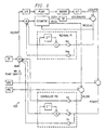
- Figure 1 is a flow chart illustrating a method 10 of adjusting a MEMS mirror control system (enumerated 100 in Figure 2) to implement calibration between the MEMS mirror control system 100 and a particular MEMS mirror ("Plant" in Figure 2) in a fashion that optimizes MEMS mirror control loop performance according to one embodiment of the present invention.
- method 10 depicts modification of (1) PID gains, (2) state estimator parameters, and (3) feed forward blocks, the present invention is not so limited. Modification of any combination of one or more of the elements (1), (2), or (3) can be implemented in accordance with the principles of the present invention.
- a more detailed functional description of control system 100 is disclosed in U.S. Patent Application No. 10/160,399, entitled Residual Feedback To Improve Estimator Prediction, filed on May 31, 2002 by Eric G.
- the controller i.e. control system 100
- the controller is then adjusted appropriately.
- the present inventors have discovered three elements of a MEMS mirror control system that will benefit from calibration based on the physical parameters of the system; and that without such calibration, a significantly more conservative controller is necessary to support the naturally wide variance in gain and resonant frequency associated with MEMS mirrors. Use of a conservative controller will then result in less than optimal system performance.
- controller elements include the PID (proportional, integral, derivative) gains, the Estimator, and the feed-forward waveform used to perform rapid seeks.
- the PID gains determine how the system (i.e. control system 100) responds to position and velocity errors, and can be calibrated using the following formulas.
- the Estimator predicts the motion of the mirror (also used in the feedback controller).
- the state Estimator can be defined by where state X1 is the position, state X2 is the velocity, and state X3 is the previous control effort.
- the term 'u' is the current control effort.
- the present inventors have also found that changes in ResFreq (MEMS mirror resonant frequency) and InvPlantGain (MEMS mirror gain) significantly affect five of the foregoing matrix coefficients according to relationships defined by
- the feed-forward (FF) waveform use to perform rapid seeks is identified by feed-forward tables that scale as the inverse of Gain2 set forth above.
- the term seek means the process of moving the MEMS mirror from one angular location to another.
- the FF element represents a feed-forward current.
- the current waveform is supplied via a FF table that is very close to the control effort necessary to perform the seek. If, for example, all feedback was turned-off, application of the FF current pulse would cause movement most of the way from the starting point to the ending point. Without use of feedback, system variability then prevents exact movement from the starting point to the ending point.
- the FF table discussed herein above includes expected seek position (Xref) and velocity (Vref) data necessary to keep the MEMS mirror on track while moving during a seek.
- Xref expected seek position
- Vref velocity
- Xref the desired position
- control system 100 calibration can then be seen to commence in block 12, by first measuring the resonant frequency (ResFreq) and the MEMS mirror gain (InvPlantGain) in order to distinctly identify those qualities associated with a specific mirror.
- the PID controller that will be used to control movement of the MEMS mirror is adjusted such that the proportional, integral and derivative gain elements will have respective gains KP, KI, and KD defined as set forth herein before.
- the State Estimator associated with the PID controller will also be adjusted as seen in block 16 such that the State Estimator parameters A13, A21, A23, B1, and B2 are defined as set forth herein before.
- the FF table parameters are scaled as the inverse of Gain2, defined herein before in terms of MEMS mirror gain and resonant frequency.
- a method of calibrating a micro-electro-mechanical system (MEMS) mirror PID control system is implemented by (1) modifying PID gains, (2) modifying a state estimator, and/or (3) modifying feed forward blocks.
- MEMS micro-electro-mechanical system
- the foregoing elements (1), (2) and (3) are not dependent upon each other, and so any combination of the foregoing elements (1), (2) and (3) may therefore be modified to implement a particular embodiment of the present invention.
- the present invention presents a significant advancement in the art of MEMS mirror positioning techniques. Further, this invention has been described in considerable detail in order to provide those skilled in the MEMS mirror art with the information needed to apply the novel principles and to construct and use such specialized components as are required. In view of the foregoing descriptions, it should be apparent that the present invention represents a significant departure from the prior art in construction and operation. However, while particular embodiments of the present invention have been described herein in detail, it is to be understood that various alterations, modifications and substitutions can be made therein without departing in any way from the scope of the present invention, as defined in the claims that follow.
Landscapes
- Physics & Mathematics (AREA)
- General Physics & Mathematics (AREA)
- Optics & Photonics (AREA)
- Micromachines (AREA)
- Mechanical Light Control Or Optical Switches (AREA)
- Mechanical Optical Scanning Systems (AREA)
- Control Of Position Or Direction (AREA)
- Lasers (AREA)
Abstract
Description

Claims (9)
- A method of calibrating a micro-electro-mechanical (MEM) mirror control system, the method comprising the steps of:providing a MEM mirror and a MEM mirror control system comprising a state estimator element;measuring the resonant frequency and gain associated with the MEM mirror; andadjusting the state estimator element such that predetermined state estimator parameters are related to the MEM mirror gain and resonant frequency.
- The method according to claim 1, wherein the controller state estimator element is defined bywherein

state X1 is the position, state X2 is the velocity, state X3 is the previous control effort, and the term 'u' is the current control effort. - The method according to claim 1 or 2, wherein the step of adjusting the state estimator element such that predetermined state estimator parameters are related to the MEM mirror gain and resonant frequency comprises adjusting parameters A13, A21, A23, B1 and B2, such thatGain1=(qResFreq/NomResFreq)^2,Gain2=Gain1*(qInvPlantGain/NomInvPlantGain), A13=NomA13*Gain2,A21=NomA21*Gainl, A23=NomA23*Gain2, B1=NomB1*Gain2, andB2=NomB2*Gain2.
- The method according to any one of Claims 1 to 3, wherein the state estimator element comprises a PID controller having proportional, integral, and derivative gain elements;
and the step of adjusting the state estimator comprises adjusting the PID controller gain elements such that each gain element has a desired gain related to the MEM mirror gain and resonant frequency. - The method according to claim 4, wherein the step of adjusting the PID controller gain elements such that each gain element has a desired gain related to the MEM mirror gain and resonant frequency comprises adjusting the proportional gain element KP such that KP=KP_Init*InvPlantGain, wherein InvPlantGain is the inverse MEM mirror gain and KP_Init is the initial proportional gain element gain.
- The method according to claim 4 or 5, wherein the step of adjusting the PID controller gain elements such that each gain element has a desired gain related to the MEM mirror gain and resonant frequency comprises adjusting the integral gain element KI such that KI=KI_Init*InvPlantGain*ResFreq, wherein InvPlantGain is the inverse MEM mirror gain and KI_Init is the initial integral gain element gain, and ResFreq is the resonant frequency of the MEM mirror.
- The method according to claim 4, 5 or 6, wherein the step of adjusting the PID controller gain elements such that each gain element has a desired gain related to the MEM mirror gain and resonant frequency comprises adjusting the differential gain element KD such that KD=KD_Init*InvPlantGain/ResFreq, wherein InvPlantGain is the inverse MEM mirror gain and KD_Init is the initial differential gain element gain, and ResFreq is the resonant frequency of the MEM mirror.
- The method according to any one of claims 4 to 7 wherein the PID controller further comprises a state estimator element, and a feed-forward control element defined in association with look-up table parameters;
scaling the feed-forward look-up table parameters such that the look-up table parameters are related to the MEM mirror gain and resonant frequency. - The method according to claim 8, wherein the step of scaling feed-forward look-up table parameters such that the look-up table parameters are related to the MEM mirror gain and resonant frequency comprises scaling the look-up table parameters as the inverse of Gain2, whereinGain2=Gainl*(qInvPlantGain/NomInvPlantGain), andGain1=(qResFreq/NomResFreq)^2, and further wherein InvPlantGainis the inverse gain associated with the MEM mirror andNomResFreq is the nominal resonant frequency of the MEM mirror.
Applications Claiming Priority (2)
| Application Number | Priority Date | Filing Date | Title |
|---|---|---|---|
| US162482 | 2002-06-03 | ||
| US10/162,482 US6708082B2 (en) | 2002-06-03 | 2002-06-03 | System identification to improve control of a micro-electro-mechanical mirror |
Publications (2)
| Publication Number | Publication Date |
|---|---|
| EP1369732A2 true EP1369732A2 (en) | 2003-12-10 |
| EP1369732A3 EP1369732A3 (en) | 2005-02-16 |
Family
ID=29549315
Family Applications (1)
| Application Number | Title | Priority Date | Filing Date |
|---|---|---|---|
| EP03101594A Withdrawn EP1369732A3 (en) | 2002-06-03 | 2003-06-02 | System identification to improve control of a micro-electro-mechanical mirror |
Country Status (3)
| Country | Link |
|---|---|
| US (1) | US6708082B2 (en) |
| EP (1) | EP1369732A3 (en) |
| JP (1) | JP2004029779A (en) |
Cited By (2)
| Publication number | Priority date | Publication date | Assignee | Title |
|---|---|---|---|---|
| WO2009028739A1 (en) * | 2007-08-30 | 2009-03-05 | Canon Kabushiki Kaisha | Oscillator device, optical deflector and image forming apparatus using the same |
| CN111308888A (en) * | 2019-12-12 | 2020-06-19 | 山东大学 | Gain strategy-based micro-electromechanical system control method and system |
Families Citing this family (6)
| Publication number | Priority date | Publication date | Assignee | Title |
|---|---|---|---|---|
| JP4039150B2 (en) * | 2002-07-09 | 2008-01-30 | 株式会社デンソー | Optical switch subsystem |
| US7368846B2 (en) * | 2002-11-06 | 2008-05-06 | Matsushita Electric Industrial Co., Ltd. | Microactuator with displacement sensing function and deformable mirror including the microactuator |
| US7096741B2 (en) * | 2004-07-14 | 2006-08-29 | Jds Uniphase Corporation | Method and system for reducing operational shock sensitivity of MEMS devices |
| US20100166430A1 (en) * | 2008-12-26 | 2010-07-01 | Steve Alten | Broadcast optical interconnect using a MEMS mirror |
| CN105278331A (en) * | 2015-05-26 | 2016-01-27 | 河海大学常州校区 | Robust-adaptive neural network H-infinity control method of MEMS gyroscope |
| CN107064055B (en) * | 2017-03-03 | 2019-07-23 | 南京富岛信息工程有限公司 | A method of improving MEMS near infrared spectrometer absorbance repeatability |
Family Cites Families (7)
| Publication number | Priority date | Publication date | Assignee | Title |
|---|---|---|---|---|
| US5369345A (en) * | 1992-03-31 | 1994-11-29 | Seagate Technology, Inc. | Method and apparatus for adaptive control |
| US5893054A (en) * | 1993-09-07 | 1999-04-06 | Boeing North American, Inc. | Amplitude detection and automatic gain control of a sparsely sampled sinusoid by computation including a hilbert transform |
| US6275326B1 (en) * | 1999-09-21 | 2001-08-14 | Lucent Technologies Inc. | Control arrangement for microelectromechanical devices and systems |
| US6301965B1 (en) * | 1999-12-14 | 2001-10-16 | Sandia Corporation | Microelectromechanical accelerometer with resonance-cancelling control circuit including an idle state |
| US6427038B1 (en) * | 2000-08-15 | 2002-07-30 | At&T Corp | Mirror control of micro-electro-mechanical optical cross connect switch |
| US6470110B1 (en) * | 2000-10-19 | 2002-10-22 | Tellium, Inc. | Monolithic integration of control elements and micro-mirror in an optical switch |
| US6538802B2 (en) * | 2001-07-31 | 2003-03-25 | Axsun Technologies, Inc | System and method for tilt mirror calibration due to capacitive sensor drift |
-
2002
- 2002-06-03 US US10/162,482 patent/US6708082B2/en not_active Expired - Lifetime
-
2003
- 2003-06-02 EP EP03101594A patent/EP1369732A3/en not_active Withdrawn
- 2003-06-02 JP JP2003156718A patent/JP2004029779A/en active Pending
Cited By (4)
| Publication number | Priority date | Publication date | Assignee | Title |
|---|---|---|---|---|
| WO2009028739A1 (en) * | 2007-08-30 | 2009-03-05 | Canon Kabushiki Kaisha | Oscillator device, optical deflector and image forming apparatus using the same |
| US8159734B2 (en) | 2007-08-30 | 2012-04-17 | Canon Kabushiki Kaisha | Oscillator device, optical deflector and image forming apparatus using the same |
| CN111308888A (en) * | 2019-12-12 | 2020-06-19 | 山东大学 | Gain strategy-based micro-electromechanical system control method and system |
| CN111308888B (en) * | 2019-12-12 | 2021-05-28 | 山东大学 | A control method and system for a microelectromechanical system based on a gain strategy |
Also Published As
| Publication number | Publication date |
|---|---|
| US20030225463A1 (en) | 2003-12-04 |
| EP1369732A3 (en) | 2005-02-16 |
| US6708082B2 (en) | 2004-03-16 |
| JP2004029779A (en) | 2004-01-29 |
Similar Documents
| Publication | Publication Date | Title |
|---|---|---|
| KR900005546B1 (en) | Adaptive Process Control | |
| EP1278109B1 (en) | Tuned open-loop switched to closed-loop method for rapid point-to-point movement of a periodic motion control system | |
| US7886535B2 (en) | Position control method for shape memory alloy actuator | |
| US7190144B2 (en) | System and method for adjusting a PID controller in a limited rotation motor system | |
| JP3215067B2 (en) | Position correction method when moving direction is reversed | |
| US7283321B1 (en) | Disk drives and methods allowing for dual stage actuator adaptive seek control and microactuator gain calibration | |
| EP1439440A2 (en) | Servo motor drive control device | |
| US20090174357A1 (en) | Servo motor controller | |
| US5847874A (en) | Control apparatus for positional control of an optical system | |
| JP3545006B2 (en) | Two-degree-of-freedom controller and servo controller for electric motor | |
| US6708082B2 (en) | System identification to improve control of a micro-electro-mechanical mirror | |
| JP2008310651A (en) | Two-degree-of-freedom control device and control method thereof | |
| US7345448B2 (en) | Adaptive command filtering for servomechanism control systems | |
| EP0779565B1 (en) | Constant delay filtering for synchronized motion on multiple axes | |
| KR980004823A (en) | Method and apparatus for disturbance compensation of an actuator | |
| US20050222695A1 (en) | Sliding mode controller position control device | |
| US20080111514A1 (en) | Servo Control Apparatus | |
| JP2001222324A (en) | Positioning control device and positioning control method | |
| JP2003169488A (en) | Servo motor control device and control method | |
| WO2003083850A3 (en) | Method and device for performing tilt correction using multi-dimensional actuator | |
| JP2003044102A (en) | Learning control method | |
| JPH06187041A (en) | Apparatus and method for compensation of warming-up drift ofservomotor | |
| JP4078396B2 (en) | Positioning control device | |
| US20090040647A1 (en) | Magnetic disk apparatus and magnetic head control method | |
| JPH07111642B2 (en) | Sliding mode control method |
Legal Events
| Date | Code | Title | Description |
|---|---|---|---|
| PUAI | Public reference made under article 153(3) epc to a published international application that has entered the european phase |
Free format text: ORIGINAL CODE: 0009012 |
|
| AK | Designated contracting states |
Kind code of ref document: A2 Designated state(s): AT BE BG CH CY CZ DE DK EE ES FI FR GB GR HU IE IT LI LU MC NL PT RO SE SI SK TR |
|
| AX | Request for extension of the european patent |
Extension state: AL LT LV MK |
|
| PUAL | Search report despatched |
Free format text: ORIGINAL CODE: 0009013 |
|
| AK | Designated contracting states |
Kind code of ref document: A3 Designated state(s): AT BE BG CH CY CZ DE DK EE ES FI FR GB GR HU IE IT LI LU MC NL PT RO SE SI SK TR |
|
| AX | Request for extension of the european patent |
Extension state: AL LT LV MK |
|
| 17P | Request for examination filed |
Effective date: 20050816 |
|
| AKX | Designation fees paid |
Designated state(s): DE FR GB |
|
| STAA | Information on the status of an ep patent application or granted ep patent |
Free format text: STATUS: THE APPLICATION IS DEEMED TO BE WITHDRAWN |
|
| 18D | Application deemed to be withdrawn |
Effective date: 20060208 |