EP1369585A2 - Pump - Google Patents
Pump Download PDFInfo
- Publication number
- EP1369585A2 EP1369585A2 EP03012515A EP03012515A EP1369585A2 EP 1369585 A2 EP1369585 A2 EP 1369585A2 EP 03012515 A EP03012515 A EP 03012515A EP 03012515 A EP03012515 A EP 03012515A EP 1369585 A2 EP1369585 A2 EP 1369585A2
- Authority
- EP
- European Patent Office
- Prior art keywords
- pump
- pressure
- pump chamber
- cycle
- moving wall
- Prior art date
- Legal status (The legal status is an assumption and is not a legal conclusion. Google has not performed a legal analysis and makes no representation as to the accuracy of the status listed.)
- Granted
Links
- 239000012530 fluid Substances 0.000 claims abstract description 167
- 230000004913 activation Effects 0.000 claims abstract description 9
- 238000006073 displacement reaction Methods 0.000 claims description 57
- 230000008859 change Effects 0.000 claims description 29
- 230000003247 decreasing effect Effects 0.000 abstract description 12
- 238000005086 pumping Methods 0.000 abstract description 4
- 238000000034 method Methods 0.000 description 85
- 230000008569 process Effects 0.000 description 69
- 238000006243 chemical reaction Methods 0.000 description 16
- 238000010586 diagram Methods 0.000 description 12
- 230000007423 decrease Effects 0.000 description 10
- 238000012937 correction Methods 0.000 description 7
- 238000007906 compression Methods 0.000 description 6
- 230000006835 compression Effects 0.000 description 5
- 239000007788 liquid Substances 0.000 description 5
- 238000005259 measurement Methods 0.000 description 5
- 230000008901 benefit Effects 0.000 description 4
- 238000002474 experimental method Methods 0.000 description 3
- 230000004044 response Effects 0.000 description 3
- 238000005273 aeration Methods 0.000 description 2
- 230000010354 integration Effects 0.000 description 2
- 230000007246 mechanism Effects 0.000 description 2
- 230000001360 synchronised effect Effects 0.000 description 2
- 230000001131 transforming effect Effects 0.000 description 2
- LFQSCWFLJHTTHZ-UHFFFAOYSA-N Ethanol Chemical compound CCO LFQSCWFLJHTTHZ-UHFFFAOYSA-N 0.000 description 1
- 230000003213 activating effect Effects 0.000 description 1
- 239000000654 additive Substances 0.000 description 1
- 230000008602 contraction Effects 0.000 description 1
- 238000000708 deep reactive-ion etching Methods 0.000 description 1
- 230000001419 dependent effect Effects 0.000 description 1
- 230000002542 deteriorative effect Effects 0.000 description 1
- 230000000694 effects Effects 0.000 description 1
- 238000011068 loading method Methods 0.000 description 1
- 239000000463 material Substances 0.000 description 1
- 230000001737 promoting effect Effects 0.000 description 1
- 230000009467 reduction Effects 0.000 description 1
- 229920006395 saturated elastomer Polymers 0.000 description 1
- 238000013519 translation Methods 0.000 description 1
- 238000011144 upstream manufacturing Methods 0.000 description 1
- XLYOFNOQVPJJNP-UHFFFAOYSA-N water Substances O XLYOFNOQVPJJNP-UHFFFAOYSA-N 0.000 description 1
Images







Classifications
-
- F—MECHANICAL ENGINEERING; LIGHTING; HEATING; WEAPONS; BLASTING
- F04—POSITIVE - DISPLACEMENT MACHINES FOR LIQUIDS; PUMPS FOR LIQUIDS OR ELASTIC FLUIDS
- F04B—POSITIVE-DISPLACEMENT MACHINES FOR LIQUIDS; PUMPS
- F04B43/00—Machines, pumps, or pumping installations having flexible working members
- F04B43/02—Machines, pumps, or pumping installations having flexible working members having plate-like flexible members, e.g. diaphragms
- F04B43/04—Pumps having electric drive
- F04B43/043—Micropumps
- F04B43/046—Micropumps with piezoelectric drive
-
- F—MECHANICAL ENGINEERING; LIGHTING; HEATING; WEAPONS; BLASTING
- F04—POSITIVE - DISPLACEMENT MACHINES FOR LIQUIDS; PUMPS FOR LIQUIDS OR ELASTIC FLUIDS
- F04B—POSITIVE-DISPLACEMENT MACHINES FOR LIQUIDS; PUMPS
- F04B49/00—Control, e.g. of pump delivery, or pump pressure of, or safety measures for, machines, pumps, or pumping installations, not otherwise provided for, or of interest apart from, groups F04B1/00 - F04B47/00
- F04B49/06—Control using electricity
- F04B49/065—Control using electricity and making use of computers
Definitions
- the present invention relates to a positive displacement pump in which the volume of a pump chamber is changed by a piston, a diaphragm or the like to move fluid, and more specifically, it relates to a reliable pump with high flow rate.
- this type of conventional pumps have an arrangement in which check valves are disposed between a suction channel and a discharge channel and a pump chamber the volume of which can be varied (for example, refer to Patent Document 1).
- a pump with an arrangement in which a mounting part is not provided and in which both the suction channel and the discharge channel have a compression component having a channel shape in which pressure drop varies depending on the direction of the flow (for example, refer to Patent Document 3 and Non-patent Document 1).
- Patent Document 1 poses a problem that both the suction channel and the discharge channel require a check valve, causing a loss of pressure when fluid passes through the two check valves. Also, the check valves are repeatedly opened and closed, causing possible fatigue damages. There is also a problem of deteriorating reliability with an increase in the number of the check valves.
- the flow resistance of the suction channel must be high in order to decrease backflow generated in the suction channel during a pump discharge process.
- the pump suction process becomes fairly longer than the discharge process in order to introduce the fluid into the pump chamber against the flow resistance. Accordingly, the frequency of the discharge/suction cycle of the pump becomes fairly low.
- Patent Document 3 With the arrangement of Patent Document 3, the net quantity of fluid that passes though the compression component in response to the variations in the volume of the pump chamber is let flow in one direction owing to the difference in pressure drop depending on the direction of the flow. Accordingly, backflow is increased with an increase in the external pressure (load pressure) at the pump outlet, thus posing a problem that the pump does not operate at high load pressure.
- the maximum load pressure is about 0.760 atmospheric pressure.
- the suction channel denotes a channel to the fluid inflow end face of the inlet connecting pipe.
- pulse absorbing means When pulse absorbing means is connected in the middle of the pipe, however, it denotes a channel from the pump chamber to the connection with the pulse absorbing means.
- the suction channels of a plurality of pumps when joined, it denotes a channel from the pump chamber to the joint. Ditto for the discharge channel.
- Providing the cycle control means prevents useless consumption of the removed fluid volume to increase the volume and pressure of the discharged fluid of the pump, thus providing a pump with high driving efficiency.
- the cycle control means changes the motion cycle of the moving wall depending on the load pressure downstream from the discharge channel.
- the cycle control means changes the motion cycle of the moving wall depending on the displacement time, the displacement amount, or the displacement rate in the pump-chamber-capacity compression process of the moving wall.
- the cycle control means changes the motion cycle of the moving wall in accordance with the sense information of pump-pressure sensing means for sensing the pressure in the pump.
- the cycle control means controls to start the next motion of the moving wall when the pump-pressure sensing means senses an increase in pressure after the completion of the previous motion of the moving wall.
- the cycle control means changes the motion cycle of the moving wall in accordance with a calculation value using a predetermined value and the sensed value of the pump-pressure sensing means.
- the predetermined value is the pressure in the pump chamber which is measured by the pump-pressure sensing means before the driving of the actuator.
- the predetermined value is the pressure in the pump chamber which is measured by the pump-pressure sensing means after a lapse of a predetermined time from the previous application of the drive waveform.
- the predetermined value is a value inputted in advance and substantially corresponding to the load pressure downstream from the discharge channel.
- load-pressure sensing means for sensing the load pressure downstream from the discharge channel, wherein the predetermined value is a value measured by the load-pressure sensing means.
- the calculation value is obtained by time-integrating the difference between the sensed value and the predetermined value for the period during which the value sensed by the pump-pressure sensing means is larger than the predetermined value.
- a passive valve in the suction channel, wherein the cycle control means senses the displacement of the valve and changes the motion cycle of the moving wall on the basis of the sensed value.
- the cycle control means changes the motion cycle of the moving wall in accordance with the sense information of flow velocity measuring means for sensing the flow velocity of the downstream including the discharge channel.
- the cycle control means controls to start the next motion of the moving wall after the flow velocity measuring means has sensed an increase in flow velocity from the completion of the previous motion of the moving wall.
- the cycle control means changes the motion cycle of the moving wall depending on the difference between the maximum value and the minimum value of the flow velocity measured by the flow velocity measuring means.
- the cycle control means changes the motion cycle of the moving wall in accordance with the sense information of moving-fluid-volume measuring means for sensing the suction volume of the suction channel or the discharged volume of the discharge channel.
- the discharged fluid volume can be increased and the durability of the check valve can be improved.
- the actuator itself can be driven with less displacement without decreasing the volume of fluid discharged from the pump, so that the inner loss of the actuator is decreased, thus offering an advantage of driving the pump with high efficiency.
- the total inertance of the suction channel be lower than the total inertance of the discharge channel for increasing the suction flow rate and increasing the discharged fluid volume.
- the discharge channel is opened to the pump chamber during the operation of the pump.
- the actuator is a piezoelectric element.
- the actuator is a giant magnetostrictive element.
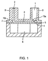
- Fig. 1 is a longitudinal sectional view of the pump of the present invention, in which a circular diaphragm 5 is arranged on the bottom of a cylindrical casing 7. The outer edge of diaphragm 5 is fixed to the casing 7 such that it can be elastically deformed.
- a piezoelectric element 6 extending vertically in the drawing is arranged on the bottom of the diaphragm 5, as an actuator for moving the diaphragm 5.
- a narrow space between the diaphragm 5 and the top wall of the casing 7 serves as a pump chamber 3.
- a suction channel 1 and a discharge channel 2 are opened to the pump chamber 3, the suction channel 1 having a check valve 4 serving as a flow resistance element and the discharge channel 2 being a tubular channel including a narrow hole which is always open to the pump chamber even during the operation of the pump.
- Part of the periphery of a component that constitutes the suction channel 1 serves as an inlet connecting pipe 8 for connecting an external element (not shown) with the pump.
- Part of the periphery of a component that constitutes the discharge channel 2 serves as an outlet connecting tube 9 for connecting an external element (not shown) with the pump.
- Both the suction channel and the discharge channel have chamfered portions 15a and 15b, which are chamfered on the working-fluid inlet side, respectively.
- Inertance L is now defined.
- the inertance L designates the degree of influence of the unit pressure on changes in flow rate. The larger the inertance L, the smaller the change in flow rate is. The smaller the inertance L, the larger the flow rate change is.
- the total inertance for the parallel connection of a plurality of channels and the serial connection of a plurality of channels having different shapes may be obtained by combining the respective inertance values of the channels in a manner similar to the parallel connection and the serial connection of inductances in an electrical circuit.
- the suction channel in this case denotes a channel to the end face of the fluid inlet of the inlet connecting pipe 8.
- the channel has pulse absorbing means connected in the middle thereof, however, it denotes a channel from the inside of the pump chamber 3 to the connection with the pulse absorbing means.
- the plurality of suction channels 1 of a pump when joined, it denotes a channel from the inside of the pump chamber 3 to the joint section. Ditto for the discharge channel.
- the reference symbols of the lengths and the areas of the suction channel 1 and the discharge channel 2 will be described.
- the length of the small-diameter pipe near the check valve 4 is L1 and its area is S1
- the length of the remaining large-diameter pipe is L2 and its area is S2.
- the length of the path of the discharge channel 2 is L3 and its area is S3.
- the inertance of the suction channel 1 is calculated by ⁇ L1/S1+ ⁇ L2/S2.
- the inertance of the discharge channel 2 is calculated as ⁇ L3/S3.
- the channels have dimensional relationship that satisfies ⁇ L1/S1+ ⁇ L2/S2 ⁇ ⁇ L3/S3.
- the shape of the diaphragm 5 is not limited to a circle. Also, for example, even if the discharge channel 2 has a valve element for protecting pump components from excessive load pressure which may be applied when the pump is possibly stopped, there is no problem as long as it is open to the pump chamber during at least the operation of the pump.
- the check valve 4 may be not only of a type of opening and closing with the differential pressure of the fluid, but of a type of controlling the opening and the closing by a force other than the differential pressure of the fluid.
- the actuator 6 for moving the diaphragm 5 may be made of any extendable material. With the pump structure of the present invention, however, the actuator and the diaphragm 5 are connected without using a displacement increasing mechanism, and so the diaphragm can be driven at high frequencies. Accordingly, the use of the piezoelectric element 6 with high response frequency as in this embodiment increases the flow rate by high frequency driving, thus providing a compact high-output pump. Similarly, giant magnetostrictive elements with high frequency response may be used.
- a mechanical switching valve may be arranged only at the suction channel, a decrease in flow rate due to valves is reduced and also a high reliability is provided.
- water is used as working fluid to be introduced into the pump.
- other liquids including alcohol-based liquids, oil-based liquids, and liquids with additives, may be used.
- Fig. 2 shows a waveform W1 of the displacement of the diaphragm 5, a waveform W2 of the inner pressure of the pump chamber 3, a waveform W3 of the volume velocity of the fluid that passes through the discharge channel 2 (the cross-sectional area of the discharge channel x the flow velocity of the fluid, which is equal to the flow rate in this case), and the waveform of a volume velocity W4 of the liquid that passes through the check valve 4, during the operation of the pump.
- a load pressure P fu shown in Fig. 2 is a fluid pressure downstream from the discharge channel 2.
- a suction pressure P ky is a fluid pressure upstream from the suction channel 1.
- the positive slope of the waveform W1 shows the process of decreasing the volume of the pump chamber 3 by the extension of the piezoelectric element 6.
- the negative slope of the waveform W1 shows the process of increasing the capacity of the pump chamber 3 by the contraction of the piezoelectric element 6.
- the flat waveform portion with a displacement of about 4.5 ⁇ m shows the maximum displacement of the diaphragm 5, that is, the displacement position of the diaphragm 5 where the volume of the pump chamber 3 becomes minimum.
- the inner pressure of the pump chamber 3 starts to increase, as shown by the waveform W2 indicating variations of the inner pressure in the pump chamber 3.
- the inner pressure of the pump chamber 3 starts to decrease after it has reached the maximum inner pressure of the pump chamber 3.
- the point of the maximum inner pressure is a point where the volume velocity of the fluid removed by the diaphragm 5 becomes equal to the volume velocity of the fluid in the discharge channel 2 shown by the waveform W3.
- the period during which the pressure in the pump chamber 3 is higher than the load pressure P fu is substantially the period during which the volume velocity of the fluid increases, as shown by the waveform W3 indicating the fluid volume velocity in the discharge channel 2.
- the pressure in the pump chamber 3 becomes lower than the load pressure P fu the volume velocity of the fluid in the discharge channel 2 starts to decrease.
- ⁇ P out R out Q out + L out ⁇ dQ out dt
- ⁇ P out the differential pressure between the pressure in the pump chamber 3 and the load pressure P fu
- R out is the flow resistance in the discharge channel 2
- L out is the inertance
- Q out is the volume velocity of the fluid.
- the change rate in the fluid volume velocity equals a value obtained by dividing the difference between ⁇ P out and R out ⁇ Q out by the inertance L out .
- a value obtained by integrating the fluid volume velocity shown by the waveform W3 of one cycle is the discharged fluid volume for one cycle.
- the check valve 4 In the suction channel 1, when the pressure in the pump chamber 3 becomes lower than the suction pressure P ky , the check valve 4 is opened by the differential pressure. Then the fluid volume velocity increases, as shown by the waveform W4 designating the change in the volume velocity of the fluid that passes through the check valve 4. When the pressure in the pump chamber 3 becomes higher than the suction pressure P ky , the fluid volume velocity begins to decrease. The check effect of the check valve 4 prevents backward flow.
- ⁇ P in R in ⁇ Q in + L in ⁇ dQ in dt
- ⁇ P in the differential pressure between the pressure in the pump chamber 3 and the suction pressure P ky
- R in is the flow resistance In the discharge channel 2
- L in is the inertance
- Q in is the volume velocity of the fluid.
- the change rate in the fluid volume velocity equals a value obtained by dividing the difference between ⁇ P in and R in ⁇ Q in by the inertance L in of the suction channel 1.
- a value obtained by integrating the fluid volume velocity shown by the waveform W4 of one cycle is the suction fluid volume for one cycle.
- the suction fluid volume is equal to the discharged fluid volume calculated by the waveform W3.
- the inertance is constant, the larger the integral of the differential pressure of both ends of a channel, the larger the change in the volume velocity Q of the in-channel fluid during the period is.
- the larger the integral of the differential pressure between the inner pressure of the pump chamber 3 and the load pressure P fu the faster the flow (also having a great momentum) toward the outlet of the fluid in the discharge channel 2 is to increase the discharged fluid volume.
- a lot of fluid can be introduced from the suction channel 1 into the pump chamber 3 by the time when the momentum decreases, and accordingly, the time until the discharged fluid volume and the suction fluid volume become equal to each other is increased.
- the displacement rate in the process of decreasing the volume of the pump chamber by the diaphragm is increased, the value on the left side of the expression (3) tends to increase.
- Fig. 3 shows two peaks of the discharged fluid volume.
- Figs. 4 and 5 shows a driving state called a 1 ⁇ x wave mode in which the cycle of diaphragm displacement and the cycle of the pressure in the pump chamber are equal to each other.
- Fig. 4 shows a driving state called a 1 ⁇ x wave mode in which the cycle of diaphragm displacement and the cycle of the pressure in the pump chamber are equal to each other.
- FIG. 5 shows a driving state called a 2 ⁇ x wave mode in which the cycle of the pressure in the pump chamber is twice as long as the cycle of diaphragm displacement.
- the pressure waveforms in the pump chamber in Figs. 4 and 5 differ from each other, and the respective values on the left side of the expression (3) also differ. More specifically, the peak of the pressure waveform in the 2 ⁇ x wave mode of Fig. 5 is higher than that of the 1 ⁇ x wave mode of Fig. 4, and the value on the left side of the expression (3) is also larger. Accordingly, the time when the discharged fluid volume and the suction fluid volume become equal also changes. (In Fig. 5 showing the 2 ⁇ x wave mode, the time until the discharged fluid volume and the suction fluid volume become equal is longer than that in Fig.
- the peak of the discharged fluid volume shown in Fig.3 is at a driving frequency at which the time when the discharge fluid volume and the suction fluid volume become equal is well synchronized with the period during which the diaphragm is moved in the direction to reduce the volume of the pump chamber.
- the reason why the pressure waveforms in the pump chamber differ between the two modes is because the displacements of the diaphragm are equal, but in comparison with Fig.4, the driving cycle in Fig. 5 is shorter, so that the displacement rate in the process of decreasing the volume of the pump chamber by the diaphragm is higher in Fig. 5..
- the pressure in the pump chamber 3 is significantly influenced particularly by the time when the diaphragm 5 is displaced to decrease the volume of the pump chamber 3 by the actuation of the piezoelectric element 6, the maximum displacement, the displacement rate, and the change in load pressure; accordingly, the time when the discharged fluid volume and the suction fluid volume become equal also varies, and furthermore, the optimum timing to apply the next driving voltage to the piezoelectric element 6 after the previous application of the driving voltage varies.
- the discharged fluid volume is increased by the generation of 2 ⁇ x wave rather than in 1 ⁇ x wave.
- the number of switching operations of the check valve becomes one half of the driving frequency by the driving in 2 ⁇ x wave mode.
- the number of switching operations of the check valve driven in 2 ⁇ x wave mode is smaller than that in 1 ⁇ x wave mode.
- fatigue fracture is related to the repetition number of loadings. Therefore, the durability of the check valve is further increased by driving in 2 ⁇ x wave mode.
- the driving waveform of the diaphragm is sinusoidal; however, the same applies to the case of driving with a waveform close to a sinusoidal waveform or a driving waveform in which the displacement rate of the diaphragm serves as the function of the driving cycle.
- the peak frequency of the discharged fluid volume in Fig. 3 is a driving frequency at which the time when the discharge fluid volume and the suction fluid volume become equal (the time when the inner pressure of the pump chamber becomes equal to the load pressure) is well synchronized every time with the period during which the diaphragm is moved in the direction to reduce the volume of the pump chamber.
- the frequency is referred to as an in-pump fluid resonance frequency.
- the resonance frequency of the mechanical components that constitute the pump chamber, such as the actuator, the diaphragm, other wall components of the pump chamber, (the volume change of the pump chamber 3 becomes maximum at that frequency) is substantially equalized to the in-pump fluid resonance frequency, so that the actuator itself can be driven with less displacement without decreasing the volume of fluid discharged from the pump, which offers an advantage of decreasing the inner loss of the actuator to drive the pump with high efficiency.
- Figs. 6 and 7 show a first embodiment according to the present invention.
- Fig. 6 is a block diagram of driving means 20 for controlling the driving of the piezoelectric element 6 of this embodiment, composed of a cycle control circuit 22 and a voltage-waveform generation circuit 24.
- the voltage-waveform generation circuit 24 includes a waveform generation circuit 24a for generating a voltage waveform once each time it receives a trigger signal, which will be discussed later, the voltage waveform having been set before the reception of the trigger signal, and an amplifier circuit 24b which supplies the electric power required for driving the piezoelectric element 6.
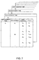
- the cycle control circuit 22 includes an I/O port 22a into which signals for the time (displacement time) to displace the diaphragm 5 in the direction to decrease the volume of the pump chamber 3, the maximum displacement, and the load pressure are inputted, a ROM 22b which experimentally obtains the optimum motion cycle in advance for the combination of the respective input values and records maps shown in Fig. 7, and a CPU 22c for generating a trigger signal with a corresponding cycle with reference to the ROM 22b with the input values to the I/O port 22a.
- the cycle control circuit 22 selects the optimum cycle for the displacement time, the maximum displacement, and the change in load pressure to control the piezoelectric element 6, and thus the diaphragm 5 is displaced in a state in which the discharged fluid volume and the suction fluid volume are equal or the suction fluid volume is large, thereby preventing useless consumption of the removed fluid volume and increasing the discharged fluid volume of the pump.
- the pump chamber 3 since there is no need to provide a sensor in the pump chamber 3, it is preferable when the pump chamber 3 is a narrow space.
- Figs. 8 and 9 show a second embodiment of the present invention.
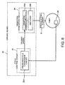
- the driving means 20 shown in Fig. 8 includes the cycle control circuit 22 and the voltage-waveform generation circuit 24.
- the voltage-waveform generation circuit 24 has the same arrangement as that of the block diagram shown in Fig. 6.
- the circuit 24 generates a voltage waveform being set before a trigger signal is received once each time it receives the trigger signal, which will be described later.
- the cycle control circuit 22 includes a pressure/cycle conversion circuit 22d for generating a trigger signal on the basis of a value sensed by a pressure sensor 28 arranged in the pump.
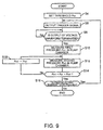
- Fig. 9 shows a flowchart of the procedure of the pressure/cycle conversion circuit 22d.
- step S4 first, the threshold P sh of the pressure is set.
- the threshold P sh uses a value larger than an output value when a suction pressure P ky is applied to the pressure sensor 28. This eliminates erroneous sensing due to slight pressure rise at low pressure.
- step S6 wherein a trigger signal is output to the voltage-waveform generation circuit 24.
- step S8 it is checked whether one output of the voltage waveform has been finished by the voltage-waveform generation circuit 24. When it has been finished, the process moves to step S10.
- step S10 the pressure sensor 28 measures the first pressure P in1 in the pump chamber 3.
- step S12 the pressure sensor 28 measures the second pressure P in2 in the pump chamber 3.
- step S14 it is determined whether the relationship among the threshold P sh , the first pressure P in1 in the pump chamber 3, and the second pressure P in2 in the pump chamber 3 establishes P in1 ⁇ P sh ⁇ P in2 .
- the process proceeds to S16, and when the relation P in1 ⁇ P sh ⁇ P in2 has not been established, the process proceeds to S18.
- step S18 the value of the second pressure P in2 in the pump chamber 3 is set as the first pressure P in1 in the pump chamber 3, and the process returns to step S12.
- step S16 it is determined whether the control of the piezoelectric element 6 is continued or stopped, wherein when the control of the piezoelectric element 6 is stopped, the process is stopped, and when the control of the piezoelectric element 6 is continued, the process returns to step S6.
- the cycle control circuit 22 can apply the next driving voltage to the piezoelectric element 6 at the point of time when the pressure in the pump chamber 3 has exceeded the preset threshold P sh for the change in load pressure.
- the diaphragm 5 When a value larger than the output when the load pressure P fu is applied to the pressure sensor 28 is used, the diaphragm 5 begins to be displaced when the discharged fluid volume and the suction fluid volume are equal or the suction fluid volume is larger, thereby preventing useless consumption of the removed fluid volume and increasing the discharged fluid volume of the pump.
- a strain gauge or a displacement sensor may be used to measure the strain of the diaphragm to calculate the pressure in the pump chamber 3, to except for the sensor which measures pressure directly like pressure sensor 28. It is also possible to measure the deformation of the pump frame with a strain gauge to calculate the pressure in the pump chamber 3. Furthermore, it is possible to provide a passive valve in the suction channel 1 wherein the deformation by the pressure in the pump chamber 3 with the valve closed is measured by the strain gauge or the displacement sensor to calculate the pressure in the pump chamber 3.
- the piezoelectric element 6 with a strain gauge to measure the displacement of the piezoelectric element 6 wherein the pressure in the pump chamber 3 may be calculated on the basis of the voltage applied to the piezoelectric element 6, or the applied charge (target displacement), the measurement (actual displacement) by the strain gauge, and the modulus of elasticity of the piezoelectric element 6. According to such method, there is no need to arrange those measuring means in the pump chamber 3, thus promoting the reduction of the size of the pump. Any types of strain gauges may be used in which the strain is sensed from a resistance change, capacitance change, or voltage change.
- the pressure sensor in the pump including the pump chamber and discharge channel.
- it is arranged in the pump chamber because the pressure in the pump can accurately be measured.
- Fig. 10 shows a third embodiment of the present invention.
- step S32 it is checked whether the calculation of an calculation value F i , which will be described later, has been finished for all the cycles T i .
- step S38 the process moves to step S36.
- step s38 a trigger signal S i is output.
- step S44 the pressure P in in the pump chamber 3 is measured by the pressure sensor 28.
- step S46 it is determined whether the relationship between the reference value (predetermined value) P a and the pressure P in in the pump chamber 3 establishes the relation P a ⁇ P in , where the reference value P a is the pressure in the pump chamber 3 before the piezoelectric element 6 is activated.
- the process moves to step S50, and when the relation P a ⁇ P in has not been established, the process returns to step S44.
- step S54 the pressure in the pump chamber is measured and it is checked whether the relationship between the measurement P in and the reference value P a establishes the relation P a > P in .
- the process moves to step S56, and when the relation P a > P in has not been established, the process returns to step S50.
- step S56 the difference between the storage pressure P mj and the reference value P a is time-integrated to calculate the calculation value F i using the storage pressure P mj , the reference value P a , and the elapsed time TM mj , and the process then returns to S30.
- step S36 that is a destination of procedure after the calculation of the calculation value F i for all the cycles T i of the diaphragm 5 has been finished in step S32, the maximum value of the stored calculation values F 1 , F 2 , F 3 ⁇ is calculated.
- step S58 After the cycle T i of the diaphragm 5 that corresponds to the maximum calculation value F i has been selected, the process is finished.
- the driving means 20 then controls the activation of the piezoelectric element 6 so that the diaphragm 5 is displaced with the selected cycle T i .
- a cycle can be selected in which the calculation value F i corresponding to the left side of the expression (3) becomes maximum.
- the activation is performed with the optimum cycle to start the displacement of the diaphragm 5 at the point of time when the discharged fluid volume and the suction fluid volume are equal or the suction fluid volume is larger, useless consumption of the removed fluid volume is eliminated in the process of reducing the volume of the pump chamber, as described above.
- the inner pressure of the pump chamber is further increased, the discharged fluid volume of the pump is also increased, and the value corresponding to the left side of the expression (3) is also increased, as compared with the driving with a nonoptimum cycle. Consequently, controlling the motion cycle of the diaphragm, as in this embodiment, allows driving with the optimum motion cycle to prevent useless consumption of the removed fluid volume to increase the discharged fluid volume of the pump.
- the time-integration of the difference between the pressure P mj and the reference value P a allows accurate control of the piezoelectric element 6.
- the integral of the difference between the peak value of the pressure P in of the pump chamber 3 and the reference value P a and the time when the reference value P a ⁇ P in is satisfied can also be used.
- the load pressure P fu can be found by measuring the pressure in the pump chamber 3 before the driving.
- the load pressure P fu can be obtained by other methods without setting the pressure in the pump before the driving of the piezoelectric element 6 as the reference value P a, to perform the process of the third embodiment shown in Fig. 10.
- the load pressure P fu when the load pressure P fu is known in advance, it is simple and desirable to use this value. It is also preferable to provide means for measuring the load pressure P fu and to use the measured value because it can respond to various load pressures P fu which cannot be estimated.
- operation of the pump is temporally stopped by a few waves during the operation of the pump (for example, when operated at 2 kHz, it is stopped for 10 waves after the operation of 2,000 waves and is then operated through 2,000 waves), the pressure vibration of the pump chamber 3 is stopped during the stop. Accordingly, the pressure in the pump chamber 3 is equal to the load pressure P fu .
- the value of the pressure sensor 28 serving as the pump-pressure sensing means at that time as the load pressure P fu because it can respond to various load pressures P fu and also there is no need to provide new additional means for measuring the load pressure.
- a calculation value F i in a certain motion cycle and a correction value to be added to the motion cycle for making it an ideal maximum calculation value F max are obtained in advance by experiment or the like, and they are held in the ROM serving as displacement control means in the map form.
- the displacement rate can be controlled at higher speed while offering similar advantages.
- Figs. 11 and 12 show a fourth embodiment of the present invention.
- the cycle control circuit 22 of this embodiment includes an I/O port 22a, a ROM 22b, and a CPU 22c, wherein the pressure information of the pump chamber 3 is inputted to the I/O port 22a from the pressure sensor 28 arranged in the pump.
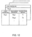
- the ROM 22b the peak inner pressure of the pressure sensor 28 in a certain reference motion cycle T 0 and a correction value for making it the optimum cycle, which are obtained by experiment in advance, are recorded as maps for each load pressure, as shown in Fig. 12.
- the cycle control circuit 22 When the waveform generation circuit 24 of this embodiment outputs a first driving voltage, the cycle control circuit 22 generates a trigger signal with the reference motion cycle T 0 , and the waveform generation circuit 24 starts a second output of driving voltage, measurement by the pressure sensor 28 is started, and a peak value is calculated from the measured value; thereafter, a corresponding correction amount is found with reference to the ROM 22b, and a trigger signal is output with cycles in which the correction amount is added to the reference motion cycle from the next time. For obtaining the load pressure, all the methods described in the third embodiment may be employed similarly.
- the driving voltage waveform is transmitted to the piezoelectric element 6 with a selected optimum cycle, so that the diaphragm 5 is displaced in a state in which the discharged fluid volume and the suction fluid volume are equal or the suction fluid volume is larger. Accordingly, useless consumption of the removed fluid volume can be prevented to increase the discharged fluid volume of the pump.
- Figs. 13 and 14 show a fifth embodiment according to the present invention.
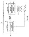
- the driving means 20 of this embodiment shown in Fig. 13 includes the cycle control circuit 22 and the voltage-waveform generation circuit 24.
- the cycle control circuit 22 includes a displacement/cycle conversion circuit 22e for generating a trigger signal on the basis of a value sensed by a displacement sensor 30 that senses the displacement state of the switching of the check valve 4 which is provided in the suction channel 1 in the pump and is opened or closed by the pressure difference.
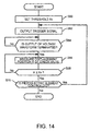
- Fig. 14 shows a flowchart of the procedure of the displacement/cycle conversion circuit 22e.
- step S60 first, a threshold X 0 is set which corresponds to the displacement amount when the check valve 4 for closing the suction channel 1 is substantially closed.
- step S62 wherein a trigger signal is output.
- step S64 it is checked whether one output of the voltage waveform has been finished, and when it has been finished, the process proceeds to step S66.
- step S66 the displacement X of the check valve 4 is measured by the displacement sensor 30.
- step S68 it is checked whether the relationship between the displacement (threshold) X 0 of the check valve 4 for closing the suction channel 1 and the measured displacement X establishes X ⁇ X 0 .
- the process proceeds to step S70.
- the process returns to step S66.
- step S70 a determination is made as to whether the control of the piezoelectric element 6 is continued or stopped, wherein when the control of the piezoelectric element 6 is stopped, the process is stopped, and when the control of the piezoelectric element 6 is continued, the process returns to step S62.
- This embodiment makes use of the fact that after the application of the driving voltage of one cycle has been completed, the increased amount of the suction fluid volume gradually becomes larger than the increased amount of the discharged fluid volume and when the discharged fluid volume and the suction fluid volume become substantially equal, the check valve is closed. Accordingly, the displacement/cycle conversion circuit 22e operates to apply the next driving voltage to the piezoelectric element 6 at the point of time when the check valve 4 closes the suction channel 1, so that the diaphragm 5 begins to be displaced at the point in time when the discharged fluid volume and the suction fluid volume become substantially equal. Consequently, useless consumption of the removed fluid volume can be prevented to increase the discharged fluid volume of the pump.
- Figs. 15 and 16 show a sixth embodiment according to the present invention.
- the driving means 20 shown in Fig. 15 includes the cycle control circuit 22 and the voltage-waveform generation circuit 24.
- the cycle control circuit 22 includes a flow-velocity/cycle conversion circuit 22f for generating a trigger signal on the basis of a value sensed by a flow velocity sensor 32 arranged in the discharge channel 2 in the pump.
- Fig. 16 shows a flowchart of the procedure of the flow-velocity/cycle conversion circuit 22f.
- step S74 it is checked whether the calculation of a flow velocity difference ⁇ V i , which will be described later, has been finished for all the cycles T i .
- step S80 the process moves to step S80, and when it has been finished, the process moves to step S78.
- step S80 a trigger signal S, is output.
- step S84 the maximum flow velocity V max in the discharge channel 2 is calculated.
- step S86 the minimum flow velocity V min in the discharge channel 2 is calculated.
- step S90 the difference ⁇ V between the maximum flow velocity V max and the minimum flow velocity V min is calculated.
- step S78 the maximum value of the stored velocity difference ⁇ V 1 , ⁇ V 2 , ⁇ V 3 ⁇ is calculated.
- step S94 the cycle T i that corresponds to the maximum velocity difference ⁇ V i has been selected, and the process is finished.
- the driving means 20 then controls the activation of the piezoelectric element 6 so that the diaphragm 5 is displaced with the selected cycle T i .
- the embodiment makes use of the fact that the difference in fluid volume velocity during the integration, and the time integral of the pressure difference between the pressure in the pump chamber 3 and the load pressure corresponds one to one, as shown in the expression (3), and that the more desirable the motion cycle with which the diagram is actuated, the larger the time integral is. Consequently, by the process of the flow-velocitylcycle conversion circuit 22f shown in Fig. 16, the diaphragm can be actuated with the optimum motion cycle; accordingly, useless consumption of the removed fluid volume can be prevented to increase the discharged fluid volume of the pump. Thus, a pump with a high driving efficiency can be provided.
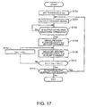
- Fig. 17 shows a flowchart of the procedure of the flow-velocity/cycle conversion circuit 22f of a seventh embodiment.
- step S100 first, a threshold V sh of the flow velocity in the discharge channel 2 is set.
- step S102 wherein a trigger signal is output.
- step S104 it is checked whether one output of the voltage waveform has been finished, wherein when it has been finished, the process proceeds to step S106.
- step S106 the first flow velocity V in1 of the discharge channel 2 is measured by a flow velocity sensor 32.
- step S108 the second flow velocity V in2 of the discharge channel 2 is measured by the flow velocity sensor 32.
- step S110 it is checked whether the relationship among the threshold V sh , the first flow velocity V in1 of the discharge channel 2, and the second flow velocity V in2 of the discharge channel 2 has established the relation V in1 ⁇ V sh ⁇ V in2 .
- the process moves to step S112, and when the relation V in1 ⁇ V sh ⁇ V in2 has not been satisfied, the process moves to step S114.
- step S114 the value of the second flow velocity V in2 of the discharge channel 2 is set as the first flow velocity V in1 of the discharge channel 2, and the process returns to step S108.
- step S112 a determination is made as to whether the control of the piezoelectric element 6 is continued or stopped, wherein when the control of the piezoelectric element 6 is stopped, the process is stopped, and when the control of the piezoelectric element 6 is continued, the process returns to step S102.
- This embodiment makes use of the fact that the flow velocity of the fluid in the discharge channel 2 decreases during the period of time when the inner pressure of the pump is lower than the load pressure after the completion of one application of the driving voltage, as shown in Fig. 2, and that when the discharged fluid volume and the suction fluid volume become equal or the suction fluid volume becomes larger, the inner pressure of the pump becomes higher than the load pressure to increase the flow velocity in the discharge channel 2.
- the diaphragm 5 begins to be displaced at the point of time when the discharged fluid volume and the suction fluid volume become equal or the suction fluid volume becomes larger. Consequently, useless consumption of the removed fluid volume is prevented to increase the discharged fluid volume of the pump.
- measurement by the flow velocity sensor 32 is started when the diaphragm is moved with the reference cycle T 0 under the conditions of the known diaphragm displacement rate and load pressure; a peak value is calculated from the measured value; the corresponding correction amount is found with reference to the maps in the ROM; and a trigger signal is output from the next time with a cycle in which the correction amount is added to the reference cycle T 0 .
- an ultrasonic system for the flow velocity sensor 32, an ultrasonic system, a measuring system of converting the flow velocity to a pressure, and a hot-wire flow sensor may be used. It is sufficient to arrange the flow velocity sensor 32 downstream including the discharge channel.
- Fig. 18 shows an eighth embodiment according to the present invention.
- a chamber 40 capable of storing fluid is connected to the discharge channel 2 of the pump.
- the chamber 40 and a fluid level sensor 42 provided therein constitute moving-fluid-volume measuring means, wherein sense information on the fluid level is inputted from the fluid level sensor 42 to the driving means 20.
- the chamber 40 is empty initially.
- the driving means 20 measures the discharge time and the fluid level to calculate the discharge volume of the diaphragm 5 per unit time.
- the motion cycle of the diaphragm 5 is set as appropriate so that the discharge volume becomes maximum. Consequently, the diaphragm can be moved with the optimum cycle such that the discharged fluid volume per unit time becomes maximum.
- a pump with a high driving efficiency can be provided.
- a pulse absorbing buffer may be provided at the suction channel 1 or the discharge channel 2 in place of the moving-fluid-volume measuring means which consisted of the chamber 40 and the fluid level sensor 42, for measuring and outputting the displacement of the film of the buffer, wherein the motion cycle of the diaphragm 5 may be set so that the displacement of the buffer film becomes maximum.
- the pump according to the present invention may have a valve only at the suction channel and a flow resistance element such as a valve only at the suction channel. Accordingly, the loss of pressure due to flow resistance elements can be reduced and the reliability of the pump can be increased.
- a displacement enlarging mechanism is not disposed between the piston or the diaphragm and the actuator for activating it, and the valve does not use viscous resistance, thus being ready for high frequency driving. Accordingly, a compact lightweight pump with high output that makes the most of the performance of the actuator can be realized.
- Providing the cycle control means prevents useless consumption of the removed fluid volume, thus increasing the corresponding discharged fluid volume and discharge pressure of the pump. Accordingly, a pump with a high driving efficiency can be provided.
Landscapes
- Engineering & Computer Science (AREA)
- Mechanical Engineering (AREA)
- General Engineering & Computer Science (AREA)
- Computer Hardware Design (AREA)
- Reciprocating Pumps (AREA)
- Control Of Positive-Displacement Pumps (AREA)
Abstract
Description
- The present invention relates to a positive displacement pump in which the volume of a pump chamber is changed by a piston, a diaphragm or the like to move fluid, and more specifically, it relates to a reliable pump with high flow rate.
- Generally, this type of conventional pumps have an arrangement in which check valves are disposed between a suction channel and a discharge channel and a pump chamber the volume of which can be varied (for example, refer to Patent Document 1).
- There is also an arrangement of a pump for producing one-directional flow using viscous resistance of fluid, which has a valve in the discharge channel wherein when the valve is opened, the suction channel has higher flow resistance than the discharge channel (for example, refer to Patent Document 2).
- In order to improve the reliability of a pump, there is also provided a pump with an arrangement in which a mounting part is not provided and in which both the suction channel and the discharge channel have a compression component having a channel shape in which pressure drop varies depending on the direction of the flow (for example, refer to
Patent Document 3 and Non-patent Document 1). - [Patent Document 1] Japanese Unexamined Patent Application Publication No. 10-220357
- [Patent Document 2] Japanese Unexamined Patent Application Publication No. 08-312537
- [Patent Document 3] PCT Japanese Translation Patent Publication No. 08-506874
- [Non-patent Document 1] Anders Olsson, An improved valve-less pump fabricate using deep reactive ion etching, 1996 IEEE 9th International Workshop on Micro Electro Mechanical Systems, p.479-484
-
- The arrangement of
Patent Document 1, however, poses a problem that both the suction channel and the discharge channel require a check valve, causing a loss of pressure when fluid passes through the two check valves. Also, the check valves are repeatedly opened and closed, causing possible fatigue damages. There is also a problem of deteriorating reliability with an increase in the number of the check valves. - In the arrangement of
Patent Document 2, the flow resistance of the suction channel must be high in order to decrease backflow generated in the suction channel during a pump discharge process. Thus, the pump suction process becomes fairly longer than the discharge process in order to introduce the fluid into the pump chamber against the flow resistance. Accordingly, the frequency of the discharge/suction cycle of the pump becomes fairly low. - In the pump in which a piston or a diaphragm is vertically moved, the higher the frequency for vertical movement, the higher the flow rate and output become, with the piston or the diaphragm having the same area. With the arrangement of
Patent Document 2, however, activation is allowed only with low frequency, as described above, thus posing a problem in that a compact high-output pump cannot be provided. - With the arrangement of
Patent Document 3, the net quantity of fluid that passes though the compression component in response to the variations in the volume of the pump chamber is let flow in one direction owing to the difference in pressure drop depending on the direction of the flow. Accordingly, backflow is increased with an increase in the external pressure (load pressure) at the pump outlet, thus posing a problem that the pump does not operate at high load pressure. According toNon-patent Document 1, the maximum load pressure is about 0.760 atmospheric pressure. - Accordingly, it is an object of the present invention to provide a pump with high driving efficiency in which the number of mechanical switching valves is decreased to reduce pressure loss and reliability is improved, and which is ready for high load pressure and high-frequency driving, and which increases the discharged fluid volume of the pump.
- These objects are achieved by a pump as claimed in
claims 1, 17 and 18, respectively. Preferred embodiments of the invention are subject-matter of the dependent claims. - The inertance L mentioned in
claim 1 is given by the expression L = ρ·I/S, where S is the cross-sectional area of the channel, I is the length of the channel, and ρ is the density of the working fluid. The relation ΔP = L·dQ/dt is derived by transforming the equation of motion of the in-channel fluid using the inertance L, where ΔP is the differential pressure of the channel and Q is the flow rate of the channel. More specifically, the inertance L indicates the degree of influence exerted on the change of the flow rate by unit pressure, wherein the larger the inertance L, the smaller the change of the flow rate is, and the smaller the inertance L, the larger the change of the flow rate is. - To obtain total (combined) inertance for a parallel connection of a plurality of channels or a series connection of a plurality of channels with different shapes the respective inertance values of the channels are combined in a manner similar to the parallel connection and series connection of inductances in an electrical circuit.
- In this case, the suction channel denotes a channel to the fluid inflow end face of the inlet connecting pipe. When pulse absorbing means is connected in the middle of the pipe, however, it denotes a channel from the pump chamber to the connection with the pulse absorbing means. Furthermore, when the suction channels of a plurality of pumps are joined, it denotes a channel from the pump chamber to the joint. Ditto for the discharge channel.
- According to the pump as in
Claim 1, since the total inertance of the suction channel is smaller than that of the discharge channel, the fluid of the suction channel flows in at high flow-rate change to increase the suction fluid volume (= discharge fluid volume). - Providing the cycle control means prevents useless consumption of the removed fluid volume to increase the volume and pressure of the discharged fluid of the pump, thus providing a pump with high driving efficiency.
- As in
Claim 2, preferably, the cycle control means changes the motion cycle of the moving wall depending on the load pressure downstream from the discharge channel. - As in
Claim 3, preferably, the cycle control means changes the motion cycle of the moving wall depending on the displacement time, the displacement amount, or the displacement rate in the pump-chamber-capacity compression process of the moving wall. - As in
Claim 4, preferably, the cycle control means changes the motion cycle of the moving wall in accordance with the sense information of pump-pressure sensing means for sensing the pressure in the pump. - As in
Claim 5, preferably, the cycle control means controls to start the next motion of the moving wall when the pump-pressure sensing means senses an increase in pressure after the completion of the previous motion of the moving wall. - As in
Claim 6, preferably, the cycle control means changes the motion cycle of the moving wall in accordance with a calculation value using a predetermined value and the sensed value of the pump-pressure sensing means. - As in
Claim 7, preferably, the predetermined value is the pressure in the pump chamber which is measured by the pump-pressure sensing means before the driving of the actuator. - As in
Claim 8, preferably, the predetermined value is the pressure in the pump chamber which is measured by the pump-pressure sensing means after a lapse of a predetermined time from the previous application of the drive waveform. - As in
Claim 9, preferably, the predetermined value is a value inputted in advance and substantially corresponding to the load pressure downstream from the discharge channel. - As in
Claim 10, preferably, there is provided load-pressure sensing means for sensing the load pressure downstream from the discharge channel, wherein the predetermined value is a value measured by the load-pressure sensing means. - As in Claim 11, preferably, the calculation value is obtained by time-integrating the difference between the sensed value and the predetermined value for the period during which the value sensed by the pump-pressure sensing means is larger than the predetermined value.
- As in Claim 12, preferably, there is provided a passive valve in the suction channel, wherein the cycle control means senses the displacement of the valve and changes the motion cycle of the moving wall on the basis of the sensed value.
- As in Claim 13, preferably, the cycle control means changes the motion cycle of the moving wall in accordance with the sense information of flow velocity measuring means for sensing the flow velocity of the downstream including the discharge channel.
- As in
Claim 14, preferably, the cycle control means controls to start the next motion of the moving wall after the flow velocity measuring means has sensed an increase in flow velocity from the completion of the previous motion of the moving wall. - As in
Claim 15, preferably, the cycle control means changes the motion cycle of the moving wall depending on the difference between the maximum value and the minimum value of the flow velocity measured by the flow velocity measuring means. - As in Claim 16, preferably, the cycle control means changes the motion cycle of the moving wall in accordance with the sense information of moving-fluid-volume measuring means for sensing the suction volume of the suction channel or the discharged volume of the discharge channel.
- According to the embodiment of Claim 17, the discharged fluid volume can be increased and the durability of the check valve can be improved.
- According to the embodiment of Claim 18, the actuator itself can be driven with less displacement without decreasing the volume of fluid discharged from the pump, so that the inner loss of the actuator is decreased, thus offering an advantage of driving the pump with high efficiency.
- As in Claim 19, in case of Claims 17 to 18, it is preferable that the total inertance of the suction channel be lower than the total inertance of the discharge channel for increasing the suction flow rate and increasing the discharged fluid volume.
- As in
Claim 20, in case of Claims 17 to 19, preferably, the discharge channel is opened to the pump chamber during the operation of the pump. - As in Claim 21, in case of
Claims 1 to 20, preferably, the actuator is a piezoelectric element. - As in
Claim 22, in case ofClaims 1 to 20, alternatively, the actuator is a giant magnetostrictive element. - Embodiments of the present invention will be described with reference to the drawings below, in which:
- Fig. 1
- is a longitudinal sectional view of a pump according to a first embodiment of the present invention.
- Fig. 2
- is a graph showing the operation of the pump according to the first embodiment.
- Fig. 3
- is a graph showing the variation of discharged fluid volume with frequency changes.
- Fig. 4
- is a graph showing a wave mode with a prescribed frequency.
- Fig. 5
- is a graph showing a wave mode with a different frequency from that of Fig. 4.
- Fig. 6
- is a block diagram of cycle control means according to the first embodiment of the present invention.
- Fig. 7
- is a diagram showing maps stored by the cycle control means according to the first embodiment.
- Fig. 8
- is a block diagram of cycle control means according to a second embodiment of the present invention.
- Fig. 9
- is a flowchart showing the procedure of the cycle control means according to the second embodiment of the present invention.
- Fig. 10
- is a flowchart showing the procedure of a pressure/cycle conversion circuit according to a third embodiment of the present invention.
- Fig. 11
- is a block diagram of cycle control means according to a fourth embodiment of the present invention.
- Fig. 12
- is a diagram showing maps stored with the cycle control means according to the fourth embodiment.
- Fig. 13
- is a block diagram of cycle control means according to a fifth embodiment of the present invention.
- Fig. 14
- is a flowchart showing the procedure of a displacement/cycle conversion circuit according to the fifth embodiment of the present invention.
- Fig. 15
- is a block diagram of cycle control means according to a sixth embodiment of the present invention.
- Fig. 16
- is a flowchart showing the procedure of a flow-velocity/cycle conversion circuit according to the sixth embodiment of the present invention.
- Fig. 17
- is a flowchart showing the procedure of flow-velocity/cycle conversion circuit according to a seventh embodiment of the present invention.
- Fig. 18
- is a diagram of a pump according to an eighth embodiment of the present invention.
- Referring to Fig. 1, the arrangement of a pump according to the embodiments of the present invention will be described. Fig. 1 is a longitudinal sectional view of the pump of the present invention, in which a
circular diaphragm 5 is arranged on the bottom of acylindrical casing 7. The outer edge ofdiaphragm 5 is fixed to thecasing 7 such that it can be elastically deformed. Apiezoelectric element 6 extending vertically in the drawing is arranged on the bottom of thediaphragm 5, as an actuator for moving thediaphragm 5. - A narrow space between the
diaphragm 5 and the top wall of thecasing 7 serves as apump chamber 3. Asuction channel 1 and adischarge channel 2 are opened to thepump chamber 3, thesuction channel 1 having acheck valve 4 serving as a flow resistance element and thedischarge channel 2 being a tubular channel including a narrow hole which is always open to the pump chamber even during the operation of the pump. Part of the periphery of a component that constitutes thesuction channel 1 serves as aninlet connecting pipe 8 for connecting an external element (not shown) with the pump. Part of the periphery of a component that constitutes thedischarge channel 2 serves as anoutlet connecting tube 9 for connecting an external element (not shown) with the pump. Both the suction channel and the discharge channel have chamferedportions - Inertance L is now defined. The inertance L can be obtained by equation L = ρ·I/S, where S is the cross-sectional area of the channel, I is the length of the channel, and ρ is the density of the working fluid. The relation ΔP = L·dQ/dt can be derived by transforming the equation of motion of the in-channel fluid using the inertance L, where ΔP is the differential pressure of the channel, and Q is the flow rate in the channel.
- More specifically, the inertance L designates the degree of influence of the unit pressure on changes in flow rate. The larger the inertance L, the smaller the change in flow rate is. The smaller the inertance L, the larger the flow rate change is.
- The total inertance for the parallel connection of a plurality of channels and the serial connection of a plurality of channels having different shapes may be obtained by combining the respective inertance values of the channels in a manner similar to the parallel connection and the serial connection of inductances in an electrical circuit.
- The suction channel in this case denotes a channel to the end face of the fluid inlet of the
inlet connecting pipe 8. When the channel has pulse absorbing means connected in the middle thereof, however, it denotes a channel from the inside of thepump chamber 3 to the connection with the pulse absorbing means. Furthermore, when the plurality ofsuction channels 1 of a pump are joined, it denotes a channel from the inside of thepump chamber 3 to the joint section. Ditto for the discharge channel. - Referring to Fig. 1, the reference symbols of the lengths and the areas of the
suction channel 1 and thedischarge channel 2 will be described. In thesuction channel 1, the length of the small-diameter pipe near thecheck valve 4 is L1 and its area is S1, and the length of the remaining large-diameter pipe is L2 and its area is S2. In thedischarge channel 2, the length of the path of thedischarge channel 2 is L3 and its area is S3. - The inertance relationship between the
suction channel 1 and thedischarge channel 2 will be described using the aforesaid symbols and the density ρ of the working fluid. - The inertance of the
suction channel 1 is calculated by ρ·L1/S1+ρ·L2/S2. On the other hand, the inertance of thedischarge channel 2 is calculated as ρ·L3/S3. The channels have dimensional relationship that satisfies ρ·L1/S1+ρ·L2/S2 < ρ·L3/S3. - In the above-described arrangement, the shape of the
diaphragm 5 is not limited to a circle. Also, for example, even if thedischarge channel 2 has a valve element for protecting pump components from excessive load pressure which may be applied when the pump is possibly stopped, there is no problem as long as it is open to the pump chamber during at least the operation of the pump. Thecheck valve 4 may be not only of a type of opening and closing with the differential pressure of the fluid, but of a type of controlling the opening and the closing by a force other than the differential pressure of the fluid. - The
actuator 6 for moving thediaphragm 5 may be made of any extendable material. With the pump structure of the present invention, however, the actuator and thediaphragm 5 are connected without using a displacement increasing mechanism, and so the diaphragm can be driven at high frequencies. Accordingly, the use of thepiezoelectric element 6 with high response frequency as in this embodiment increases the flow rate by high frequency driving, thus providing a compact high-output pump. Similarly, giant magnetostrictive elements with high frequency response may be used. - Since a mechanical switching valve may be arranged only at the suction channel, a decrease in flow rate due to valves is reduced and also a high reliability is provided.
- In this embodiment and all following embodiments, water is used as working fluid to be introduced into the pump. However, other liquids including alcohol-based liquids, oil-based liquids, and liquids with additives, may be used.
- The motion cycle of the diaphragm in the arrangement shown in Fig. 1 will now be described with reference to Figs. 2, 3, 4, and 5.
- Fig. 2 shows a waveform W1 of the displacement of the
diaphragm 5, a waveform W2 of the inner pressure of thepump chamber 3, a waveform W3 of the volume velocity of the fluid that passes through the discharge channel 2 (the cross-sectional area of the discharge channel x the flow velocity of the fluid, which is equal to the flow rate in this case), and the waveform of a volume velocity W4 of the liquid that passes through thecheck valve 4, during the operation of the pump. A load pressure Pfu shown in Fig. 2 is a fluid pressure downstream from thedischarge channel 2. A suction pressure Pky is a fluid pressure upstream from thesuction channel 1. - The positive slope of the waveform W1 shows the process of decreasing the volume of the
pump chamber 3 by the extension of thepiezoelectric element 6. The negative slope of the waveform W1 shows the process of increasing the capacity of thepump chamber 3 by the contraction of thepiezoelectric element 6. - The flat waveform portion with a displacement of about 4.5 µm shows the maximum displacement of the
diaphragm 5, that is, the displacement position of thediaphragm 5 where the volume of thepump chamber 3 becomes minimum. - When the process of decreasing the volume of the
pump chamber 3 starts, the inner pressure of thepump chamber 3 starts to increase, as shown by the waveform W2 indicating variations of the inner pressure in thepump chamber 3. Before the process of decreasing the volume of thepump chamber 3 terminates, the inner pressure of thepump chamber 3 starts to decrease after it has reached the maximum inner pressure of thepump chamber 3. The point of the maximum inner pressure is a point where the volume velocity of the fluid removed by thediaphragm 5 becomes equal to the volume velocity of the fluid in thedischarge channel 2 shown by the waveform W3. - The reason is that, since before the time the inner pressure assumes its maximum, the difference (volume velocity of the removed fluid) - (volume velocity of the fluid that passes through the discharge channel 2) is greater than zero, the fluid in the
pump chamber 3 is compressed correspondingly to increase the pressure therein; and that, since this time the difference (volume velocity of the removed fluid) - (volume velocity of the fluid that passes through the discharge channel 2) is smaller than zero, the compression amount of the fluid in thepump chamber 3 is reduced correspondingly to decrease the pressure therein. - The pressure in the
pump chamber 3 varies in accordance with the relationship between the volume change ΔV and the compression ratio of the fluid, wherein ΔV = (volume of fluid removed by the diaphragm) + (volume of suction fluid) - (volume of discharged fluid), where ΔV Is the volume change in thepump chamber 3 with every moment. Accordingly, even when the volume of thepump chamber 3 is decreasing, the pressure in thepump chamber 3 can become lower than the load pressure Pfu. - In the case of Fig. 2, when the pressure in the
pump chamber 3 becomes lower than the suction pressure Pky to be close to absolute zero atmospheric pressure, aeration or cavitation occurs in which components that have dissolved in the working fluid are gasified to bubbles. And the pressure in thepump chamber 3 is saturated at about absolute zero atmospheric pressure. However, when the overall channel system including the pump is pressurized and the suction pressure Pky is sufficiently high, the aeration and cavitation may not occur. - In the
discharge channel 2, the period during which the pressure in thepump chamber 3 is higher than the load pressure Pfu is substantially the period during which the volume velocity of the fluid increases, as shown by the waveform W3 indicating the fluid volume velocity in thedischarge channel 2. When the pressure in thepump chamber 3 becomes lower than the load pressure Pfu, the volume velocity of the fluid in thedischarge channel 2 starts to decrease. - There is the following relationship in the fluid in the
discharge channel 2.pump chamber 3 and the load pressure Pfu, Rout is the flow resistance in thedischarge channel 2, Lout is the inertance, and Qout is the volume velocity of the fluid. - Therefore, the change rate in the fluid volume velocity equals a value obtained by dividing the difference between ΔPout and Rout·Qout by the inertance Lout. A value obtained by integrating the fluid volume velocity shown by the waveform W3 of one cycle is the discharged fluid volume for one cycle.
- In the
suction channel 1, when the pressure in thepump chamber 3 becomes lower than the suction pressure Pky, thecheck valve 4 is opened by the differential pressure. Then the fluid volume velocity increases, as shown by the waveform W4 designating the change in the volume velocity of the fluid that passes through thecheck valve 4. When the pressure in thepump chamber 3 becomes higher than the suction pressure Pky, the fluid volume velocity begins to decrease. The check effect of thecheck valve 4 prevents backward flow. - There is the following relationship in the fluid in the
discharge channel 1.pump chamber 3 and the suction pressure Pky, Rin is the flow resistance In thedischarge channel 2, Lin is the inertance, and Qin is the volume velocity of the fluid. - Therefore, the change rate in the fluid volume velocity equals a value obtained by dividing the difference between ΔPin and Rin·Qin by the inertance Lin of the
suction channel 1. - A value obtained by integrating the fluid volume velocity shown by the waveform W4 of one cycle is the suction fluid volume for one cycle. The suction fluid volume is equal to the discharged fluid volume calculated by the waveform W3.
- The time integration of the definition of the inertance is expressed as follows:

- Since the inertance is constant, the larger the integral of the differential pressure of both ends of a channel, the larger the change in the volume velocity Q of the in-channel fluid during the period is. For the
discharge channel 2, the larger the integral of the differential pressure between the inner pressure of thepump chamber 3 and the load pressure Pfu, the faster the flow (also having a great momentum) toward the outlet of the fluid in thedischarge channel 2 is to increase the discharged fluid volume. A lot of fluid can be introduced from thesuction channel 1 into thepump chamber 3 by the time when the momentum decreases, and accordingly, the time until the discharged fluid volume and the suction fluid volume become equal to each other is increased. In other words, in thedischarge channel 2, the discharge flow rate (= suction flow rate) of the pump for one cycle and the time until the discharged fluid volume and the suction fluid volume become equal to each other vary depending on the value on the left side of the expression (3). When the displacement rate in the process of decreasing the volume of the pump chamber by the diaphragm is increased, the value on the left side of the expression (3) tends to increase. - The timing to apply the next driving voltage to the
piezoelectric element 6 after the previous application of the driving voltage will now be described. - As described above, the pressure in the
pump chamber 3 is varied depending on the relationship between the volume change ΔV and the compression ratio of the fluid, where ΔV is the volume change of the fluid in thepump chamber 3 with every moment, and
ΔV = (fluid volume removed by the diaphragm 5) + (suction fluid volume) - (discharged fluid volume). - In the pump with this arrangement, the
discharge channel 2 and thepump chamber 3 are opened to each other, so that when ΔV = 0 is satisfied, the pressure in thepump chamber 3 becomes equal to the load pressure Pfu. Accordingly, in the range of ΔV < 0, the pressure in thepump chamber 3 is lower than the load pressure Pfu. Therefore, when the next driving voltage is applied to thepiezoelectric element 6 in the range of ΔV < 0, the removed volume until ΔV = 0 is satisfied is used to compress the fluid in thepump chamber 3 in order to make the pressure in thepump chamber 3 equal to the load pressure Pfu, which is useless. - Preventing the useless consumption of the removed volume allows an increase in the discharged fluid volume of the pump. To that end, it is recommended to apply the next driving voltage to the
piezoelectric element 6 later than the time the discharged fluid volume and the suction fluid volume become equal to each other after the driving for one pumping has been terminated (after the net fluid volume removed by thediaphragm 5 has become zero). - The pressure wave of the fluid in the
pump chamber 3, however, varies owing to various causes. When thediaphragm 5 is moved according to a sinusoidal wave, the discharged fluid volume varies for the driving cycle, as shown in Fig. 3. Fig. 3 shows two peaks of the discharged fluid volume. The pressure in thepump chamber 3 and the diaphragm displacement in the respective driving cycles corresponding to the peaks are shown in Figs. 4 and 5. Fig. 4 shows a driving state called a 1·x wave mode in which the cycle of diaphragm displacement and the cycle of the pressure in the pump chamber are equal to each other. Fig. 5 shows a driving state called a 2·x wave mode in which the cycle of the pressure in the pump chamber is twice as long as the cycle of diaphragm displacement. The pressure waveforms in the pump chamber in Figs. 4 and 5 differ from each other, and the respective values on the left side of the expression (3) also differ. More specifically, the peak of the pressure waveform in the 2·x wave mode of Fig. 5 is higher than that of the 1·x wave mode of Fig. 4, and the value on the left side of the expression (3) is also larger. Accordingly, the time when the discharged fluid volume and the suction fluid volume become equal also changes. (In Fig. 5 showing the 2·x wave mode, the time until the discharged fluid volume and the suction fluid volume become equal is longer than that in Fig. 4 showing the 1·x wave mode.) The peak of the discharged fluid volume shown in Fig.3 is at a driving frequency at which the time when the discharge fluid volume and the suction fluid volume become equal is well synchronized with the period during which the diaphragm is moved in the direction to reduce the volume of the pump chamber. The reason why the pressure waveforms in the pump chamber differ between the two modes is because the displacements of the diaphragm are equal, but in comparison with Fig.4, the driving cycle in Fig. 5 is shorter, so that the displacement rate in the process of decreasing the volume of the pump chamber by the diaphragm is higher in Fig. 5.. - As described above, the pressure in the
pump chamber 3 is significantly influenced particularly by the time when thediaphragm 5 is displaced to decrease the volume of thepump chamber 3 by the actuation of thepiezoelectric element 6, the maximum displacement, the displacement rate, and the change in load pressure; accordingly, the time when the discharged fluid volume and the suction fluid volume become equal also varies, and furthermore, the optimum timing to apply the next driving voltage to thepiezoelectric element 6 after the previous application of the driving voltage varies. - In Fig. 3, the discharged fluid volume is increased by the generation of 2·x wave rather than in 1·x wave. Also, the number of switching operations of the check valve becomes one half of the driving frequency by the driving in 2·x wave mode. As shown in Fig. 3, the number of switching operations of the check valve driven in 2·x wave mode is smaller than that in 1·x wave mode. Generally, fatigue fracture is related to the repetition number of loadings. Therefore, the durability of the check valve is further increased by driving in 2·x wave mode. Fig. 3 shows a case in which the driving waveform of the diaphragm is sinusoidal; however, the same applies to the case of driving with a waveform close to a sinusoidal waveform or a driving waveform in which the displacement rate of the diaphragm serves as the function of the driving cycle.
- As described above, the peak frequency of the discharged fluid volume in Fig. 3 is a driving frequency at which the time when the discharge fluid volume and the suction fluid volume become equal (the time when the inner pressure of the pump chamber becomes equal to the load pressure) is well synchronized every time with the period during which the diaphragm is moved in the direction to reduce the volume of the pump chamber. Here, the frequency is referred to as an in-pump fluid resonance frequency.
- The resonance frequency of the mechanical components that constitute the pump chamber, such as the actuator, the diaphragm, other wall components of the pump chamber, (the volume change of the
pump chamber 3 becomes maximum at that frequency) is substantially equalized to the in-pump fluid resonance frequency, so that the actuator itself can be driven with less displacement without decreasing the volume of fluid discharged from the pump, which offers an advantage of decreasing the inner loss of the actuator to drive the pump with high efficiency. - Figs. 6 and 7 show a first embodiment according to the present invention.
- Fig. 6 is a block diagram of driving means 20 for controlling the driving of the
piezoelectric element 6 of this embodiment, composed of acycle control circuit 22 and a voltage-waveform generation circuit 24. - The voltage-
waveform generation circuit 24 includes awaveform generation circuit 24a for generating a voltage waveform once each time it receives a trigger signal, which will be discussed later, the voltage waveform having been set before the reception of the trigger signal, and anamplifier circuit 24b which supplies the electric power required for driving thepiezoelectric element 6. - The
cycle control circuit 22 includes an I/O port 22a into which signals for the time (displacement time) to displace thediaphragm 5 in the direction to decrease the volume of thepump chamber 3, the maximum displacement, and the load pressure are inputted, aROM 22b which experimentally obtains the optimum motion cycle in advance for the combination of the respective input values and records maps shown in Fig. 7, and aCPU 22c for generating a trigger signal with a corresponding cycle with reference to theROM 22b with the input values to the I/O port 22a. - According to this embodiment, the
cycle control circuit 22 selects the optimum cycle for the displacement time, the maximum displacement, and the change in load pressure to control thepiezoelectric element 6, and thus thediaphragm 5 is displaced in a state in which the discharged fluid volume and the suction fluid volume are equal or the suction fluid volume is large, thereby preventing useless consumption of the removed fluid volume and increasing the discharged fluid volume of the pump. - According to this embodiment, since there is no need to provide a sensor in the
pump chamber 3, it is preferable when thepump chamber 3 is a narrow space. - Figs. 8 and 9 show a second embodiment of the present invention.
- The driving means 20 shown in Fig. 8 includes the
cycle control circuit 22 and the voltage-waveform generation circuit 24. - The voltage-
waveform generation circuit 24 has the same arrangement as that of the block diagram shown in Fig. 6. Thecircuit 24 generates a voltage waveform being set before a trigger signal is received once each time it receives the trigger signal, which will be described later. - The
cycle control circuit 22 includes a pressure/cycle conversion circuit 22d for generating a trigger signal on the basis of a value sensed by apressure sensor 28 arranged in the pump. - Fig. 9 shows a flowchart of the procedure of the pressure/
cycle conversion circuit 22d. - In step S4, first, the threshold Psh of the pressure is set. The threshold Psh uses a value larger than an output value when a suction pressure Pky is applied to the
pressure sensor 28. This eliminates erroneous sensing due to slight pressure rise at low pressure. - The process moves to step S6 wherein a trigger signal is output to the voltage-
waveform generation circuit 24. - The process then moves to step S8 wherein it is checked whether one output of the voltage waveform has been finished by the voltage-
waveform generation circuit 24. When it has been finished, the process moves to step S10. - In step S10, the
pressure sensor 28 measures the first pressure Pin1 in thepump chamber 3. - The process next moves to step S12 wherein the
pressure sensor 28 measures the second pressure Pin2 in thepump chamber 3. - The process moves to step S14 wherein it is determined whether the relationship among the threshold Psh, the first pressure Pin1 in the
pump chamber 3, and the second pressure Pin2 in thepump chamber 3 establishes Pin1 < Psh < Pin2. When the relation Pin1 < Psh < Pin2 has been established, the process proceeds to S16, and when the relation Pin1 < Psh < Pin2 has not been established, the process proceeds to S18. - In step S18, the value of the second pressure Pin2 in the
pump chamber 3 is set as the first pressure Pin1 in thepump chamber 3, and the process returns to step S12. - In step S16, it is determined whether the control of the
piezoelectric element 6 is continued or stopped, wherein when the control of thepiezoelectric element 6 is stopped, the process is stopped, and when the control of thepiezoelectric element 6 is continued, the process returns to step S6. - According to this embodiment, the
cycle control circuit 22 can apply the next driving voltage to thepiezoelectric element 6 at the point of time when the pressure in thepump chamber 3 has exceeded the preset threshold Psh for the change in load pressure. - When a value larger than the output when the load pressure Pfu is applied to the
pressure sensor 28 is used, thediaphragm 5 begins to be displaced when the discharged fluid volume and the suction fluid volume are equal or the suction fluid volume is larger, thereby preventing useless consumption of the removed fluid volume and increasing the discharged fluid volume of the pump. - For pump-pressure sensing means, a strain gauge or a displacement sensor may be used to measure the strain of the diaphragm to calculate the pressure in the
pump chamber 3, to except for the sensor which measures pressure directly likepressure sensor 28. It is also possible to measure the deformation of the pump frame with a strain gauge to calculate the pressure in thepump chamber 3. Furthermore, it is possible to provide a passive valve in thesuction channel 1 wherein the deformation by the pressure in thepump chamber 3 with the valve closed is measured by the strain gauge or the displacement sensor to calculate the pressure in thepump chamber 3. It is also possible to provide thepiezoelectric element 6 with a strain gauge to measure the displacement of thepiezoelectric element 6 wherein the pressure in thepump chamber 3 may be calculated on the basis of the voltage applied to thepiezoelectric element 6, or the applied charge (target displacement), the measurement (actual displacement) by the strain gauge, and the modulus of elasticity of thepiezoelectric element 6. According to such method, there is no need to arrange those measuring means in thepump chamber 3, thus promoting the reduction of the size of the pump. Any types of strain gauges may be used in which the strain is sensed from a resistance change, capacitance change, or voltage change. - It is sufficient to arrange the pressure sensor in the pump including the pump chamber and discharge channel. Preferably, it is arranged in the pump chamber because the pressure in the pump can accurately be measured.
- Fig. 10 shows a third embodiment of the present invention.
- This is also a flowchart showing the procedure of the pressure/
cycle conversion circuit 22d shown in Fig. 8, having the same arrangement as that of Fig. 8; therefore, the block diagram of the driving means 20 is omitted here. - In step S30, first, cycle T1 is selected from a plurality of cycles Ti (i = 1, 2, 3 ···) of the
diaphragm 5. In the subsequent processes, other cycles Ti are selected. - The process then moves to step S32 wherein it is checked whether the calculation of an calculation value Fi, which will be described later, has been finished for all the cycles Ti. When it has not been finished, the process moves to step S38, and when it has been finished, the process moves to step S36.
- In step s38, a trigger signal Si is output.
- The process then moves to step S44 wherein the pressure Pin in the
pump chamber 3 is measured by thepressure sensor 28. - The process moves to step S46 wherein it is determined whether the relationship between the reference value (predetermined value) Pa and the pressure Pin in the
pump chamber 3 establishes the relation Pa ≤ Pin, where the reference value Pa is the pressure in thepump chamber 3 before thepiezoelectric element 6 is activated. In this step, when the relation Pa ≤ Pin has been established, the process moves to step S50, and when the relation Pa ≤ Pin has not been established, the process returns to step S44. - The process then moves to step S50 wherein the pressure Pin in the
pump chamber 3 is stored as a storage pressure Pmj (the value j is increased in each step as j = 1, 2, 3 ···), and the process proceeds to step S52 wherein the time of measurement is stored as an elapsed time TMmj (j = 1, 2, 3 ···) and the process moves to step S54. - In step S54, the pressure in the pump chamber is measured and it is checked whether the relationship between the measurement Pin and the reference value Pa establishes the relation Pa > Pin. When the relation Pa > Pin has been established, the process moves to step S56, and when the relation Pa > Pin has not been established, the process returns to step S50.
- In step S56, the difference between the storage pressure Pmj and the reference value Pa is time-integrated to calculate the calculation value Fi using the storage pressure Pmj, the reference value Pa, and the elapsed time TMmj, and the process then returns to S30.
- In step S36 that is a destination of procedure after the calculation of the calculation value Fi for all the cycles Ti of the
diaphragm 5 has been finished in step S32, the maximum value of the stored calculation values F1, F2, F3 ··· is calculated. - The process moves to step S58 wherein after the cycle Ti of the
diaphragm 5 that corresponds to the maximum calculation value Fi has been selected, the process is finished. - The driving means 20 then controls the activation of the
piezoelectric element 6 so that thediaphragm 5 is displaced with the selected cycle Ti. - By the process of the pressure/
cycle conversion circuit 22d shown in Fig. 10, a cycle can be selected in which the calculation value Fi corresponding to the left side of the expression (3) becomes maximum. On the other hand, when the activation is performed with the optimum cycle to start the displacement of thediaphragm 5 at the point of time when the discharged fluid volume and the suction fluid volume are equal or the suction fluid volume is larger, useless consumption of the removed fluid volume is eliminated in the process of reducing the volume of the pump chamber, as described above. Accordingly, the inner pressure of the pump chamber is further increased, the discharged fluid volume of the pump is also increased, and the value corresponding to the left side of the expression (3) is also increased, as compared with the driving with a nonoptimum cycle. Consequently, controlling the motion cycle of the diaphragm, as in this embodiment, allows driving with the optimum motion cycle to prevent useless consumption of the removed fluid volume to increase the discharged fluid volume of the pump. - The time-integration of the difference between the pressure Pmj and the reference value Pa allows accurate control of the
piezoelectric element 6. For example, the integral of the difference between the peak value of the pressure Pin of thepump chamber 3 and the reference value Pa and the time when the reference value Pa ≤ Pin is satisfied can also be used. - In the pump according to the present invention, since the outlet pipe (downstream from the discharge channel 2) connected to the
discharge channel 2 and thepump chamber 3 communicate with each other, the pressure in thepump chamber 3 before driving is equal to the load pressure Pfu. Thus, the load pressure Pfu can be found by measuring the pressure in thepump chamber 3 before the driving. - The load pressure Pfu can be obtained by other methods without setting the pressure in the pump before the driving of the
piezoelectric element 6 as the reference value Pa, to perform the process of the third embodiment shown in Fig. 10. - According to another method, when the load pressure Pfu is known in advance, it is simple and desirable to use this value. It is also preferable to provide means for measuring the load pressure Pfu and to use the measured value because it can respond to various load pressures Pfu which cannot be estimated. When operation of the pump is temporally stopped by a few waves during the operation of the pump (for example, when operated at 2 kHz, it is stopped for 10 waves after the operation of 2,000 waves and is then operated through 2,000 waves), the pressure vibration of the
pump chamber 3 is stopped during the stop. Accordingly, the pressure in thepump chamber 3 is equal to the load pressure Pfu. Thus, it is preferable to use the value of thepressure sensor 28 serving as the pump-pressure sensing means at that time as the load pressure Pfu because it can respond to various load pressures Pfu and also there is no need to provide new additional means for measuring the load pressure. - A calculation value Fi in a certain motion cycle and a correction value to be added to the motion cycle for making it an ideal maximum calculation value Fmax are obtained in advance by experiment or the like, and they are held in the ROM serving as displacement control means in the map form. Thus, by providing means for calculating the calculation value Fi, referring to the map, and correcting the motion cycle of the
diaphragm 5, the displacement rate can be controlled at higher speed while offering similar advantages. - Figs. 11 and 12 show a fourth embodiment of the present invention.
- As shown in Fig. 11, the
cycle control circuit 22 of this embodiment includes an I/O port 22a, aROM 22b, and aCPU 22c, wherein the pressure information of thepump chamber 3 is inputted to the I/O port 22a from thepressure sensor 28 arranged in the pump. In theROM 22b, the peak inner pressure of thepressure sensor 28 in a certain reference motion cycle T0 and a correction value for making it the optimum cycle, which are obtained by experiment in advance, are recorded as maps for each load pressure, as shown in Fig. 12. - When the
waveform generation circuit 24 of this embodiment outputs a first driving voltage, thecycle control circuit 22 generates a trigger signal with the reference motion cycle T0, and thewaveform generation circuit 24 starts a second output of driving voltage, measurement by thepressure sensor 28 is started, and a peak value is calculated from the measured value; thereafter, a corresponding correction amount is found with reference to theROM 22b, and a trigger signal is output with cycles in which the correction amount is added to the reference motion cycle from the next time. For obtaining the load pressure, all the methods described in the third embodiment may be employed similarly. - Also in this embodiment, the driving voltage waveform is transmitted to the
piezoelectric element 6 with a selected optimum cycle, so that thediaphragm 5 is displaced in a state in which the discharged fluid volume and the suction fluid volume are equal or the suction fluid volume is larger. Accordingly, useless consumption of the removed fluid volume can be prevented to increase the discharged fluid volume of the pump. - Figs. 13 and 14 show a fifth embodiment according to the present invention.
- The driving means 20 of this embodiment shown in Fig. 13 includes the
cycle control circuit 22 and the voltage-waveform generation circuit 24. Thecycle control circuit 22 includes a displacement/cycle conversion circuit 22e for generating a trigger signal on the basis of a value sensed by adisplacement sensor 30 that senses the displacement state of the switching of thecheck valve 4 which is provided in thesuction channel 1 in the pump and is opened or closed by the pressure difference. - Fig. 14 shows a flowchart of the procedure of the displacement/
cycle conversion circuit 22e. - In step S60, first, a threshold X0 is set which corresponds to the displacement amount when the
check valve 4 for closing thesuction channel 1 is substantially closed. - The process moves to step S62 wherein a trigger signal is output.
- The process then moves to step S64 wherein it is checked whether one output of the voltage waveform has been finished, and when it has been finished, the process proceeds to step S66.
- In step S66, the displacement X of the
check valve 4 is measured by thedisplacement sensor 30. - Subsequently, the process moves to step S68 wherein it is checked whether the relationship between the displacement (threshold) X0 of the
check valve 4 for closing thesuction channel 1 and the measured displacement X establishes X ≤ X0. When the relation X ≤ X0 has been established, the process proceeds to step S70. When the relation X ≤ X0 has not been established, the process returns to step S66. - In step S70, a determination is made as to whether the control of the
piezoelectric element 6 is continued or stopped, wherein when the control of thepiezoelectric element 6 is stopped, the process is stopped, and when the control of thepiezoelectric element 6 is continued, the process returns to step S62. - This embodiment makes use of the fact that after the application of the driving voltage of one cycle has been completed, the increased amount of the suction fluid volume gradually becomes larger than the increased amount of the discharged fluid volume and when the discharged fluid volume and the suction fluid volume become substantially equal, the check valve is closed. Accordingly, the displacement/
cycle conversion circuit 22e operates to apply the next driving voltage to thepiezoelectric element 6 at the point of time when thecheck valve 4 closes thesuction channel 1, so that thediaphragm 5 begins to be displaced at the point in time when the discharged fluid volume and the suction fluid volume become substantially equal. Consequently, useless consumption of the removed fluid volume can be prevented to increase the discharged fluid volume of the pump. - In this embodiment, since the
piezoelectric element 6 is activated after thecheck valve 4 has been closed, the loss of the discharged fluid volume due to the backflow thereof by thediaphragm 5 through thesuction channel 1 can be prevented. - Figs. 15 and 16 show a sixth embodiment according to the present invention.
- The driving means 20 shown in Fig. 15 includes the
cycle control circuit 22 and the voltage-waveform generation circuit 24. Thecycle control circuit 22 includes a flow-velocity/cycle conversion circuit 22f for generating a trigger signal on the basis of a value sensed by aflow velocity sensor 32 arranged in thedischarge channel 2 in the pump. - Fig. 16 shows a flowchart of the procedure of the flow-velocity/
cycle conversion circuit 22f. - In step S72, first, cycle T1 is selected among the plurality of cycles Ti (i = 1, 2, 3 ···) of the
diaphragm 5. In the subsequent processes, other cycles T, are selected. - The process then moves to step S74 wherein it is checked whether the calculation of a flow velocity difference ΔVi, which will be described later, has been finished for all the cycles Ti. When it has not been finished, the process moves to step S80, and when it has been finished, the process moves to step S78.
- In step S80, a trigger signal S, is output.
- The process then moves to step S84 wherein the maximum flow velocity Vmax in the
discharge channel 2 is calculated. The process then moves to step S86 wherein the minimum flow velocity Vmin in thedischarge channel 2 is calculated. - Subsequently, the process moves to step S90 wherein the difference ΔV between the maximum flow velocity Vmax and the minimum flow velocity Vmin is calculated.
- Subsequently, the process moves to step S92 wherein the flow velocity difference ΔV is stored as storage flow velocity ΔVi (i = 1, 2, 3 ···), and the process returns to step S72.
- When the calculation of the flow velocity difference ΔVi for all the cycles Ti has been finished, the process moves to step S78 wherein the maximum value of the stored velocity difference ΔV1, ΔV2, ΔV3 ··· is calculated.
- The process then moves to step S94 wherein the cycle Ti that corresponds to the maximum velocity difference ΔVi has been selected, and the process is finished.
- The driving means 20 then controls the activation of the
piezoelectric element 6 so that thediaphragm 5 is displaced with the selected cycle Ti. - The embodiment makes use of the fact that the difference in fluid volume velocity during the integration, and the time integral of the pressure difference between the pressure in the
pump chamber 3 and the load pressure corresponds one to one, as shown in the expression (3), and that the more desirable the motion cycle with which the diagram is actuated, the larger the time integral is. Consequently, by the process of the flow-velocitylcycle conversion circuit 22f shown in Fig. 16, the diaphragm can be actuated with the optimum motion cycle; accordingly, useless consumption of the removed fluid volume can be prevented to increase the discharged fluid volume of the pump. Thus, a pump with a high driving efficiency can be provided. - Fig. 17 shows a flowchart of the procedure of the flow-velocity/
cycle conversion circuit 22f of a seventh embodiment. - In step S100, first, a threshold Vsh of the flow velocity in the
discharge channel 2 is set. - The process then moves to step S102 wherein a trigger signal is output.
- Subsequently, the process moves to step S104 wherein it is checked whether one output of the voltage waveform has been finished, wherein when it has been finished, the process proceeds to step S106.
- In step S106, the first flow velocity Vin1 of the
discharge channel 2 is measured by aflow velocity sensor 32. - The process moves to step S108 wherein the second flow velocity Vin2 of the
discharge channel 2 is measured by theflow velocity sensor 32. - The process then moves to step S110 wherein it is checked whether the relationship among the threshold Vsh, the first flow velocity Vin1 of the
discharge channel 2, and the second flow velocity Vin2 of thedischarge channel 2 has established the relation Vin1 < Vsh < Vin2. When the relation Vin1 < Vsh < Vin2 has been established, the process moves to step S112, and when the relation Vin1 < Vsh < Vin2 has not been satisfied, the process moves to step S114. - In step S114, the value of the second flow velocity Vin2 of the
discharge channel 2 is set as the first flow velocity Vin1 of thedischarge channel 2, and the process returns to step S108. - In step S112, a determination is made as to whether the control of the
piezoelectric element 6 is continued or stopped, wherein when the control of thepiezoelectric element 6 is stopped, the process is stopped, and when the control of thepiezoelectric element 6 is continued, the process returns to step S102. - This embodiment makes use of the fact that the flow velocity of the fluid in the
discharge channel 2 decreases during the period of time when the inner pressure of the pump is lower than the load pressure after the completion of one application of the driving voltage, as shown in Fig. 2, and that when the discharged fluid volume and the suction fluid volume become equal or the suction fluid volume becomes larger, the inner pressure of the pump becomes higher than the load pressure to increase the flow velocity in thedischarge channel 2. Accordingly, the next driving voltage for thepiezoelectric element 6 is applied at the point of time when the flow velocity of thedischarge channel 2 is increased, as in the flow velocity/cycle conversion circuit 22f of this embodiment, thediaphragm 5 begins to be displaced at the point of time when the discharged fluid volume and the suction fluid volume become equal or the suction fluid volume becomes larger. Consequently, useless consumption of the removed fluid volume is prevented to increase the discharged fluid volume of the pump. - There is also a method in which the peak flow velocity when the diaphragm is moved with a certain reference cycle T0 and the correction amount to be added to the reference cycle when the peak flow velocity is set to the maximum peak flow velocity are obtained in advance by experiment for each displacement rate of the diaphragm and for each load pressure, which are stored in maps in the ROM or the like that constitutes the
cycle control circuit 22. In that case, measurement by theflow velocity sensor 32 is started when the diaphragm is moved with the reference cycle T0 under the conditions of the known diaphragm displacement rate and load pressure; a peak value is calculated from the measured value; the corresponding correction amount is found with reference to the maps in the ROM; and a trigger signal is output from the next time with a cycle in which the correction amount is added to the reference cycle T0. With such an arrangement, advantages similar to those of the above-described embodiments can be offered. - For the
flow velocity sensor 32, an ultrasonic system, a measuring system of converting the flow velocity to a pressure, and a hot-wire flow sensor may be used. It is sufficient to arrange theflow velocity sensor 32 downstream including the discharge channel. - Fig. 18 shows an eighth embodiment according to the present invention.
- In this embodiment, a
chamber 40 capable of storing fluid is connected to thedischarge channel 2 of the pump. Thechamber 40 and afluid level sensor 42 provided therein constitute moving-fluid-volume measuring means, wherein sense information on the fluid level is inputted from thefluid level sensor 42 to the driving means 20. - The
chamber 40 is empty initially. When fluid is discharged from thedischarge channel 2 of the pump, the driving means 20 measures the discharge time and the fluid level to calculate the discharge volume of thediaphragm 5 per unit time. The motion cycle of thediaphragm 5 is set as appropriate so that the discharge volume becomes maximum. Consequently, the diaphragm can be moved with the optimum cycle such that the discharged fluid volume per unit time becomes maximum. Thus, a pump with a high driving efficiency can be provided. - Also, a pulse absorbing buffer, not shown, may be provided at the
suction channel 1 or thedischarge channel 2 in place of the moving-fluid-volume measuring means which consisted of thechamber 40 and thefluid level sensor 42, for measuring and outputting the displacement of the film of the buffer, wherein the motion cycle of thediaphragm 5 may be set so that the displacement of the buffer film becomes maximum. This is because the larger the discharged fluid volume (= suction fluid volume) for one cycle of pumping, the greater the amplitude with which the buffer film oscillates, so that the discharged fluid volume (= suction fluid volume) for one cycle of pumping becomes maximum when the displacement of the buffer film is maximum. - As described above, the pump according to the present invention may have a valve only at the suction channel and a flow resistance element such as a valve only at the suction channel. Accordingly, the loss of pressure due to flow resistance elements can be reduced and the reliability of the pump can be increased.
- A displacement enlarging mechanism is not disposed between the piston or the diaphragm and the actuator for activating it, and the valve does not use viscous resistance, thus being ready for high frequency driving. Accordingly, a compact lightweight pump with high output that makes the most of the performance of the actuator can be realized.
- Providing the cycle control means prevents useless consumption of the removed fluid volume, thus increasing the corresponding discharged fluid volume and discharge pressure of the pump. Accordingly, a pump with a high driving efficiency can be provided.
Claims (22)
- A pump comprising: an actuator (6) for changing the position of a moving wall (5) such as a piston and a diaphragm; driving means (20) for controlling the activation of the actuator (6); a pump chamber (3) whose volume can be varied by the displacement of the moving wall (5); a suction channel for the supply of working fluid into the pump chamber (3); and a discharge channel for the delivery of the working fluid from the pump chamber (3);
wherein the discharge channel is open to the pump chamber (3) during the operation of the pump; the total inertance of the suction channel is lower than that of the discharge channel; and the suction channel includes a flow resistance element whose flow resistance during the inflow of the working fluid into the pump chamber (3) is lower than that during the outflow; and
wherein the driving means (20) includes cycle control means (22) for changing the motion cycle period of the moving wall (5). - A pump according to Claim 1, wherein the cycle control means (22) is adapted to change the motion cycle period of the moving wall (5) depending on the load pressure downstream from the discharge channel.
- A pump according to Claim 1 or 2, wherein the cycle control means (22) is adapted to change the motion cycle period of the moving wall (5) depending on the displacement time, the displacement amount, or the displacement rate in the pump-chamber-volume reducing stroke of the moving wall (5).
- A pump according to Claim 1, wherein the cycle control means (22) is adapted to change the motion cycle period of the moving wall (5) based on the pressure in the pump as sensed by pump-pressure sensing means (28).
- A pump according to Claim 4, wherein the cycle control means (22) controls to start the next motion cycle of the moving wall (5) when the pump-pressure sensing means (28) senses an increase in pressure after the completion of the previous motion of the moving wall (5).
- A pump according to Claim 4, wherein the cycle control means (22) is adapted to change the motion cycle period of the moving wall (5) in accordance with a calculation value calculated based on a predetermined pressure value and the sensed pressure value of the pump-pressure sensing means (28).
- A pump according to Claim 6, wherein the predetermined pressure value is the pressure in the pump chamber (3) which is measured by the pump-pressure sensing means (28) before the activation of the actuator (6).
- A pump according to Claim 6, wherein the predetermined pressure value is the pressure in the pump chamber (3) which is measured by the pump-pressure sensing means (28) after lapse of a predetermined time from the previous application of a drive waveform for one motion cycle.
- A pump according to Claim 6, wherein the predetermined pressure value is a value inputted in advance and substantially corresponding to the load pressure downstream from the discharge channel.
- A pump according to Claim 6, comprising load-pressure sensing means for sensing the load pressure downstream from the discharge channel, wherein the predetermined pressure value is a value measured by the load-pressure sensing means.
- A pump according to any one of Claims 6 to 10, wherein the calculation value is a value obtained by time-integrating the difference between the sensed pressure value as obtained from the pump-pressure sensing means (28) and the predetermined pressure value for the period during which the sensed pressure value is larger than the predetermined pressure value.
- A pump according to Claim 1, comprising a passive valve in the suction channel, wherein the cycle control means (22) senses the displacement of the valve and is adapted to change the motion cycle period of the moving wall (5) on the basis of the sensed value.
- A pump according to Claim 1, wherein the cycle control means (22) is adapted to change the motion cycle period of the moving wall (5) in accordance with information sensed by flow velocity measuring means (32) for sensing the flow velocity of the downstream including the discharge channel.
- A pump according to Claim 13, wherein the cycle control means (22) controls to start the next motion cycle of the moving wall (5) after the flow velocity measuring means (32) has sensed an increase in flow velocity after the completion of the previous motion cycle of the moving wall (5).
- A pump according to Claim 13, wherein the cycle control means (22) is adapted to change the motion cycle period of the moving wall (5) depending on the difference between the maximum value and the minimum value of the flow velocity as measured by the flow velocity measuring means (32).
- A pump according to Claim 1, wherein the cycle control means (22) is adapted to change the motion cycle period of the moving wall (5) in accordance with the information sensed by moving-fluid-volume measuring means (40, 42) for sensing the suction volume of the suction channel or the discharged volume of the discharge channel.
- A pump comprising: an actuator (6) for changing the position of a moving wall (5) such as a piston and a diaphragm; driving means (20) for controlling the activation of the actuator (6); a pump chamber (3) whose volume can be varied by the displacement of the moving wall (5); a suction channel for the supply of working fluid into the pump chamber (3); and a discharge channel for the delivery of the working fluid from the pump chamber (3);
wherein the suction channel includes a flow resistance element whose flow resistance during the inflow of the working fluid into the pump chamber (3) is lower than that during the outflow; and
wherein the driving means (20) drives the actuator (6) a plurality of times during one cycle of pressure variation in the pump. - A pump comprising: an actuator (6) for changing the position of a moving wall (5) such as a piston and a diaphragm; driving means (20) for controlling the activation of the actuator (6); a pump chamber (3) whose volume can be varied by the displacement of the moving wall (5); a suction channel for the supply of working fluid into the pump chamber (3); and a discharge channel for the delivery of the working fluid from the pump chamber (3);
wherein the suction channel includes a flow resistance element whose flow resistance during the inflow of the working fluid into the pump chamber (3) is lower than that during the outflow; and
wherein the frequency at which the volume variation in the pump chamber (3) becomes maximum and the in-pump fluid resonance frequency are substantially equal. - A pump according to Claim 17 or 18, wherein the total inertance of the suction channel is lower than that of the discharge channel.
- A pump according to any one of Claims 17 to 19, wherein the discharge channel is open to the pump chamber (3) during the operation of the pump.
- A pump according to any one of Claims 1 to 20, wherein the actuator (6) is a piezoelectric element.
- A pump according to any one of Claims 1 to 20, wherein the actuator (6) is a giant magnetostrictive element.
Applications Claiming Priority (4)
| Application Number | Priority Date | Filing Date | Title |
|---|---|---|---|
| JP2002161818 | 2002-06-03 | ||
| JP2002161818 | 2002-06-03 | ||
| JP2002326913 | 2002-11-11 | ||
| JP2002326913A JP4396095B2 (en) | 2002-06-03 | 2002-11-11 | pump |
Publications (3)
| Publication Number | Publication Date |
|---|---|
| EP1369585A2 true EP1369585A2 (en) | 2003-12-10 |
| EP1369585A3 EP1369585A3 (en) | 2005-03-16 |
| EP1369585B1 EP1369585B1 (en) | 2012-10-17 |
Family
ID=29552379
Family Applications (1)
| Application Number | Title | Priority Date | Filing Date |
|---|---|---|---|
| EP03012515A Expired - Lifetime EP1369585B1 (en) | 2002-06-03 | 2003-06-02 | Pump |
Country Status (4)
| Country | Link |
|---|---|
| US (1) | US7056096B2 (en) |
| EP (1) | EP1369585B1 (en) |
| JP (1) | JP4396095B2 (en) |
| CN (1) | CN1307368C (en) |
Cited By (3)
| Publication number | Priority date | Publication date | Assignee | Title |
|---|---|---|---|---|
| FR2874976A1 (en) * | 2004-09-07 | 2006-03-10 | Telemaq Sarl | High-pressure, high-frequency fluid pump comprising a piezoelectric actuator to provide alternating deformation of a compression chamber membrane |
| EP2570671A1 (en) * | 2011-09-13 | 2013-03-20 | Seiko Epson Corporation | Fluid feed pump, fluid circulation device, medical device and electronic device |
| WO2022243697A1 (en) * | 2021-05-19 | 2022-11-24 | Ttp Ventus Limited | Microfluidic pump control |
Families Citing this family (51)
| Publication number | Priority date | Publication date | Assignee | Title |
|---|---|---|---|---|
| JP2007525622A (en) * | 2003-10-03 | 2007-09-06 | スワゲロック カンパニー | Diaphragm monitoring for flow control devices |
| JP4367086B2 (en) * | 2003-10-24 | 2009-11-18 | セイコーエプソン株式会社 | Pump drive method |
| US20050225201A1 (en) * | 2004-04-02 | 2005-10-13 | Par Technologies, Llc | Piezoelectric devices and methods and circuits for driving same |
| US7290993B2 (en) * | 2004-04-02 | 2007-11-06 | Adaptivenergy Llc | Piezoelectric devices and methods and circuits for driving same |
| US7312554B2 (en) * | 2004-04-02 | 2007-12-25 | Adaptivenergy, Llc | Piezoelectric devices and methods and circuits for driving same |
| US7287965B2 (en) * | 2004-04-02 | 2007-10-30 | Adaptiv Energy Llc | Piezoelectric devices and methods and circuits for driving same |
| US7398818B2 (en) * | 2004-12-28 | 2008-07-15 | California Institute Of Technology | Fluidic pump for heat management |
| US7267043B2 (en) * | 2004-12-30 | 2007-09-11 | Adaptivenergy, Llc | Actuators with diaphragm and methods of operating same |
| JP2006207436A (en) * | 2005-01-26 | 2006-08-10 | Matsushita Electric Works Ltd | Piezoelectric diaphragm pump |
| WO2006113344A2 (en) * | 2005-04-13 | 2006-10-26 | Par Technologies, Llc | Actuators with connected diaphragms |
| US20070129681A1 (en) * | 2005-11-01 | 2007-06-07 | Par Technologies, Llc | Piezoelectric actuation of piston within dispensing chamber |
| WO2009009131A2 (en) | 2007-07-11 | 2009-01-15 | California Institute Of Technology | Cardiac assist system using helical arrangement of contractile bands and helically-twisting cardiac assist device |
| US8597505B2 (en) | 2007-09-13 | 2013-12-03 | Fresenius Medical Care Holdings, Inc. | Portable dialysis machine |
| US9358331B2 (en) | 2007-09-13 | 2016-06-07 | Fresenius Medical Care Holdings, Inc. | Portable dialysis machine with improved reservoir heating system |
| US9308307B2 (en) | 2007-09-13 | 2016-04-12 | Fresenius Medical Care Holdings, Inc. | Manifold diaphragms |
| US8105487B2 (en) | 2007-09-25 | 2012-01-31 | Fresenius Medical Care Holdings, Inc. | Manifolds for use in conducting dialysis |
| US8240636B2 (en) | 2009-01-12 | 2012-08-14 | Fresenius Medical Care Holdings, Inc. | Valve system |
| CA3057807C (en) | 2007-11-29 | 2021-04-20 | Thomas P. Robinson | System and method for conducting hemodialysis and hemofiltration |
| US8267675B2 (en) * | 2008-06-16 | 2012-09-18 | GM Global Technology Operations LLC | High flow piezoelectric pump |
| CN101634291A (en) * | 2008-07-23 | 2010-01-27 | 微创医疗器械(上海)有限公司 | Control system and control method for output liquid amount of pump |
| JP5293031B2 (en) | 2008-09-16 | 2013-09-18 | セイコーエプソン株式会社 | Fluid ejecting apparatus and surgical instrument |
| AU2009302327C1 (en) | 2008-10-07 | 2015-09-10 | Fresenius Medical Care Holdings, Inc. | Priming system and method for dialysis systems |
| CA2739807C (en) | 2008-10-30 | 2017-02-28 | Fresenius Medical Care Holdings, Inc. | Modular, portable dialysis system |
| WO2010114932A1 (en) | 2009-03-31 | 2010-10-07 | Xcorporeal, Inc. | Modular reservoir assembly for a hemodialysis and hemofiltration system |
| US9125655B2 (en) | 2010-07-16 | 2015-09-08 | California Institute Of Technology | Correction and optimization of wave reflection in blood vessels |
| EP2469089A1 (en) * | 2010-12-23 | 2012-06-27 | Debiotech S.A. | Electronic control method and system for a piezo-electric pump |
| US20140248170A1 (en) * | 2011-09-27 | 2014-09-04 | Kikuchiseisakusho Co., Ltd. | Microdiaphragm pump |
| CN103359197B (en) | 2012-04-05 | 2015-08-19 | 科沃斯机器人有限公司 | Glass cleaning device and ambulation control method thereof |
| US9201036B2 (en) | 2012-12-21 | 2015-12-01 | Fresenius Medical Care Holdings, Inc. | Method and system of monitoring electrolyte levels and composition using capacitance or induction |
| US9157786B2 (en) | 2012-12-24 | 2015-10-13 | Fresenius Medical Care Holdings, Inc. | Load suspension and weighing system for a dialysis machine reservoir |
| US9354640B2 (en) * | 2013-11-11 | 2016-05-31 | Fresenius Medical Care Holdings, Inc. | Smart actuator for valve |
| US9765767B2 (en) * | 2015-05-11 | 2017-09-19 | The Boeing Company | Synthetic vacuum generator |
| JP6103001B2 (en) * | 2015-08-20 | 2017-03-29 | セイコーエプソン株式会社 | Drive part |
| WO2017039701A1 (en) | 2015-09-04 | 2017-03-09 | Halliburton Energy Services, Inc. | Monitoring system for pressure pump cavitation |
| CA2991701C (en) * | 2015-09-04 | 2020-09-22 | Halliburton Energy Services, Inc. | Single-sensor analysis system |
| CA2993148C (en) | 2015-09-04 | 2019-01-15 | Halliburton Energy Services, Inc. | Flow-rate monitoring system for a pressure pump |
| US10480296B2 (en) | 2015-09-04 | 2019-11-19 | Halliburton Energy Services, Inc. | Critical valve performance monitoring system |
| US10895254B2 (en) * | 2015-09-04 | 2021-01-19 | Halliburton Energy Services, Inc. | Pressure pump valve monitoring system |
| TWI611103B (en) * | 2016-02-03 | 2018-01-11 | 研能科技股份有限公司 | Control method of driving circuit of piezoelectric actuated pump and driving circuit thereof |
| US11499544B2 (en) | 2016-08-31 | 2022-11-15 | Halliburton Energy Services, Inc. | Pressure pump performance monitoring system using torque measurements |
| CA3027292C (en) | 2016-09-15 | 2020-10-13 | Halliburton Energy Services, Inc. | Pressure pump balancing system |
| JP2018103380A (en) * | 2016-12-22 | 2018-07-05 | 東芝テック株式会社 | Liquid circulation module, liquid discharge device, and liquid discharge method |
| CN107381701B (en) * | 2017-08-22 | 2020-09-01 | 西安建筑科技大学 | A kind of ozone flotation device and method using constant pressure microbubble generator to supply air |
| KR101933062B1 (en) * | 2017-09-19 | 2019-03-15 | 서강대학교산학협력단 | Pump with pressure measurement function, fluid transfortation system using the same, and operation method thereof |
| JP7020645B2 (en) * | 2017-12-21 | 2022-02-16 | 豊田合成株式会社 | pump |
| US10391515B1 (en) * | 2018-05-11 | 2019-08-27 | Andrew Norman Kerlin | Viscous fluid applicator pump |
| WO2021014444A1 (en) * | 2019-07-23 | 2021-01-28 | Innotech Ltd | Tuned micro check valves and pumps |
| US12486838B2 (en) | 2020-03-31 | 2025-12-02 | Minebea Mitsumi Inc. | Pump control device and pump control system |
| US12054924B2 (en) | 2020-05-28 | 2024-08-06 | Zurn Water, Llc | Smart and connected backflow preventer assembly |
| CN112196757A (en) * | 2020-10-04 | 2021-01-08 | 长春工业大学 | Piezoelectric stack plunger pump with double-lever amplification |
| CN114320845B (en) * | 2021-12-08 | 2024-05-28 | 吉林大学 | A piezoelectric precision infusion pump integrating drive and sensing |
Citations (3)
| Publication number | Priority date | Publication date | Assignee | Title |
|---|---|---|---|---|
| JPH08506874A (en) | 1993-02-23 | 1996-07-23 | ステーメ,エリック | Diaphragm positive displacement pump |
| JPH08312537A (en) | 1995-04-12 | 1996-11-26 | Siemens Elema Ab | Pump for viscous substance |
| JPH10220357A (en) | 1997-02-10 | 1998-08-18 | Kasei Optonix Co Ltd | Piezo pump |
Family Cites Families (14)
| Publication number | Priority date | Publication date | Assignee | Title |
|---|---|---|---|---|
| CH280618A (en) | 1949-12-14 | 1952-01-31 | Sigg Hans | Vibration pump. |
| GB741015A (en) | 1952-07-26 | 1955-11-23 | Doelz Heinrich | Improvements in and relating to oscillatory drives more particularly for small refrigerating machines |
| JPS5333866B1 (en) * | 1969-08-12 | 1978-09-18 | ||
| DE2519962A1 (en) | 1975-05-05 | 1976-11-18 | Alfons Georg Zeis | Hydraulic valves for reciprocating fluid pumps - having two flow resistances positioned for cyclic volume changes |
| JPH02248671A (en) * | 1989-03-20 | 1990-10-04 | Misuzu Erii:Kk | Quantitative force feed method of fluid |
| DE4422743A1 (en) | 1994-06-29 | 1996-01-04 | Torsten Gerlach | Micropump |
| US6074178A (en) * | 1997-04-15 | 2000-06-13 | Face International Corp. | Piezoelectrically actuated peristaltic pump |
| JP3812917B2 (en) * | 1997-05-14 | 2006-08-23 | 本田技研工業株式会社 | Piezoelectric actuator |
| JPH11182444A (en) * | 1997-10-17 | 1999-07-06 | Takumina:Kk | Control circuit of solenoid-driven pump |
| CN2332827Y (en) * | 1998-02-19 | 1999-08-11 | 何秋琼 | Diaphragm booster pump with water stop structure |
| JP2001027175A (en) * | 1999-07-12 | 2001-01-30 | Akebono Brake Res & Dev Center Ltd | Electrically-driven pump |
| JP3629405B2 (en) * | 2000-05-16 | 2005-03-16 | コニカミノルタホールディングス株式会社 | Micro pump |
| US6623256B2 (en) * | 2001-02-21 | 2003-09-23 | Seiko Epson Corporation | Pump with inertance value of the entrance passage being smaller than an inertance value of the exit passage |
| US6604909B2 (en) * | 2001-03-27 | 2003-08-12 | Aquatec Water Systems, Inc. | Diaphragm pump motor driven by a pulse width modulator circuit and activated by a pressure switch |
-
2002
- 2002-11-11 JP JP2002326913A patent/JP4396095B2/en not_active Expired - Fee Related
-
2003
- 2003-05-29 US US10/447,102 patent/US7056096B2/en not_active Expired - Lifetime
- 2003-06-02 EP EP03012515A patent/EP1369585B1/en not_active Expired - Lifetime
- 2003-06-02 CN CNB031424562A patent/CN1307368C/en not_active Expired - Fee Related
Patent Citations (3)
| Publication number | Priority date | Publication date | Assignee | Title |
|---|---|---|---|---|
| JPH08506874A (en) | 1993-02-23 | 1996-07-23 | ステーメ,エリック | Diaphragm positive displacement pump |
| JPH08312537A (en) | 1995-04-12 | 1996-11-26 | Siemens Elema Ab | Pump for viscous substance |
| JPH10220357A (en) | 1997-02-10 | 1998-08-18 | Kasei Optonix Co Ltd | Piezo pump |
Non-Patent Citations (1)
| Title |
|---|
| "IEEE 9th International Workshop on Micro Electro Mechanical Systems.", 1996, article ANDERS OLSSON: "An improved valve-less pump fabricate using dep reactive ion etching.", pages: 479 - 484 |
Cited By (6)
| Publication number | Priority date | Publication date | Assignee | Title |
|---|---|---|---|---|
| FR2874976A1 (en) * | 2004-09-07 | 2006-03-10 | Telemaq Sarl | High-pressure, high-frequency fluid pump comprising a piezoelectric actuator to provide alternating deformation of a compression chamber membrane |
| EP2570671A1 (en) * | 2011-09-13 | 2013-03-20 | Seiko Epson Corporation | Fluid feed pump, fluid circulation device, medical device and electronic device |
| CN102996395A (en) * | 2011-09-13 | 2013-03-27 | 精工爱普生株式会社 | Fluid feed pump, fluid circulation device, medical device and electronic device |
| CN102996395B (en) * | 2011-09-13 | 2016-12-21 | 精工爱普生株式会社 | Liquid-feeding pump, liquid circulating apparatus, armarium and electronic equipment |
| WO2022243697A1 (en) * | 2021-05-19 | 2022-11-24 | Ttp Ventus Limited | Microfluidic pump control |
| US12473905B2 (en) | 2021-05-19 | 2025-11-18 | Lee Ventus Limited | Microfluidic pump control |
Also Published As
| Publication number | Publication date |
|---|---|
| EP1369585A3 (en) | 2005-03-16 |
| CN1307368C (en) | 2007-03-28 |
| JP4396095B2 (en) | 2010-01-13 |
| US7056096B2 (en) | 2006-06-06 |
| JP2004060632A (en) | 2004-02-26 |
| US20040018100A1 (en) | 2004-01-29 |
| CN1467375A (en) | 2004-01-14 |
| EP1369585B1 (en) | 2012-10-17 |
Similar Documents
| Publication | Publication Date | Title |
|---|---|---|
| EP1369585A2 (en) | Pump | |
| JP4378937B2 (en) | pump | |
| US6623256B2 (en) | Pump with inertance value of the entrance passage being smaller than an inertance value of the exit passage | |
| EP1369584A2 (en) | Diaphragm pump | |
| US20050019180A1 (en) | Pump | |
| US6716002B2 (en) | Micro pump | |
| JP3035854B2 (en) | Fluid pump without check valve | |
| Tan et al. | Performance modeling of a piezohydraulic actuation system with active valves | |
| JP5862903B2 (en) | Membrane pump with inertia controlled leakage compensation valve | |
| JP4877369B2 (en) | pump | |
| JP2002322986A (en) | pump | |
| CN100480510C (en) | Method for driving pump | |
| JP2001342963A (en) | Pump, check valve for pump, and pump control method | |
| JP5003700B2 (en) | pump | |
| JP2004162547A (en) | pump | |
| JP3870847B2 (en) | pump | |
| JP2013060850A (en) | Liquid feed pump | |
| JP3894121B2 (en) | pump | |
| JP2004057349A (en) | Blood pump driving device and method for calculating blood pump output | |
| JP2013060849A (en) | Liquid feed pump | |
| JP2013060848A (en) | Liquid feed pump |
Legal Events
| Date | Code | Title | Description |
|---|---|---|---|
| PUAI | Public reference made under article 153(3) epc to a published international application that has entered the european phase |
Free format text: ORIGINAL CODE: 0009012 |
|
| AK | Designated contracting states |
Kind code of ref document: A2 Designated state(s): AT BE BG CH CY CZ DE DK EE ES FI FR GB GR HU IE IT LI LU MC NL PT RO SE SI SK TR |
|
| AX | Request for extension of the european patent |
Extension state: AL LT LV MK |
|
| PUAL | Search report despatched |
Free format text: ORIGINAL CODE: 0009013 |
|
| AK | Designated contracting states |
Kind code of ref document: A3 Designated state(s): AT BE BG CH CY CZ DE DK EE ES FI FR GB GR HU IE IT LI LU MC NL PT RO SE SI SK TR |
|
| AX | Request for extension of the european patent |
Extension state: AL LT LV MK |
|
| 17P | Request for examination filed |
Effective date: 20050525 |
|
| AKX | Designation fees paid |
Designated state(s): DE FR GB IT |
|
| R17C | First examination report despatched (corrected) |
Effective date: 20070301 |
|
| GRAP | Despatch of communication of intention to grant a patent |
Free format text: ORIGINAL CODE: EPIDOSNIGR1 |
|
| GRAS | Grant fee paid |
Free format text: ORIGINAL CODE: EPIDOSNIGR3 |
|
| GRAA | (expected) grant |
Free format text: ORIGINAL CODE: 0009210 |
|
| AK | Designated contracting states |
Kind code of ref document: B1 Designated state(s): DE FR GB IT |
|
| REG | Reference to a national code |
Ref country code: GB Ref legal event code: FG4D |
|
| REG | Reference to a national code |
Ref country code: DE Ref legal event code: R096 Ref document number: 60342347 Country of ref document: DE Effective date: 20121213 |
|
| PLBE | No opposition filed within time limit |
Free format text: ORIGINAL CODE: 0009261 |
|
| STAA | Information on the status of an ep patent application or granted ep patent |
Free format text: STATUS: NO OPPOSITION FILED WITHIN TIME LIMIT |
|
| 26N | No opposition filed |
Effective date: 20130718 |
|
| REG | Reference to a national code |
Ref country code: DE Ref legal event code: R097 Ref document number: 60342347 Country of ref document: DE Effective date: 20130718 |
|
| REG | Reference to a national code |
Ref country code: FR Ref legal event code: PLFP Year of fee payment: 14 |
|
| REG | Reference to a national code |
Ref country code: FR Ref legal event code: PLFP Year of fee payment: 15 |
|
| REG | Reference to a national code |
Ref country code: FR Ref legal event code: PLFP Year of fee payment: 16 |
|
| PGFP | Annual fee paid to national office [announced via postgrant information from national office to epo] |
Ref country code: DE Payment date: 20190521 Year of fee payment: 17 Ref country code: IT Payment date: 20190620 Year of fee payment: 17 |
|
| PGFP | Annual fee paid to national office [announced via postgrant information from national office to epo] |
Ref country code: FR Payment date: 20190510 Year of fee payment: 17 |
|
| PGFP | Annual fee paid to national office [announced via postgrant information from national office to epo] |
Ref country code: GB Payment date: 20190529 Year of fee payment: 17 |
|
| REG | Reference to a national code |
Ref country code: DE Ref legal event code: R119 Ref document number: 60342347 Country of ref document: DE |
|
| GBPC | Gb: european patent ceased through non-payment of renewal fee |
Effective date: 20200602 |
|
| PG25 | Lapsed in a contracting state [announced via postgrant information from national office to epo] |
Ref country code: FR Free format text: LAPSE BECAUSE OF NON-PAYMENT OF DUE FEES Effective date: 20200630 Ref country code: GB Free format text: LAPSE BECAUSE OF NON-PAYMENT OF DUE FEES Effective date: 20200602 |
|
| PG25 | Lapsed in a contracting state [announced via postgrant information from national office to epo] |
Ref country code: DE Free format text: LAPSE BECAUSE OF NON-PAYMENT OF DUE FEES Effective date: 20210101 |
|
| PG25 | Lapsed in a contracting state [announced via postgrant information from national office to epo] |
Ref country code: IT Free format text: LAPSE BECAUSE OF NON-PAYMENT OF DUE FEES Effective date: 20200602 |