EP1368704B1 - Camera rig - Google Patents
Camera rig Download PDFInfo
- Publication number
- EP1368704B1 EP1368704B1 EP02711061A EP02711061A EP1368704B1 EP 1368704 B1 EP1368704 B1 EP 1368704B1 EP 02711061 A EP02711061 A EP 02711061A EP 02711061 A EP02711061 A EP 02711061A EP 1368704 B1 EP1368704 B1 EP 1368704B1
- Authority
- EP
- European Patent Office
- Prior art keywords
- camera
- frame
- support means
- camera rig
- rig according
- Prior art date
- Legal status (The legal status is an assumption and is not a legal conclusion. Google has not performed a legal analysis and makes no representation as to the accuracy of the status listed.)
- Expired - Lifetime
Links
- XAGFODPZIPBFFR-UHFFFAOYSA-N aluminium Chemical compound [Al] XAGFODPZIPBFFR-UHFFFAOYSA-N 0.000 claims 1
- 229910052782 aluminium Inorganic materials 0.000 claims 1
- 239000004411 aluminium Substances 0.000 claims 1
- 239000004809 Teflon Substances 0.000 description 1
- 229920006362 Teflon® Polymers 0.000 description 1
- 238000005516 engineering process Methods 0.000 description 1
- 239000000463 material Substances 0.000 description 1
- 238000000034 method Methods 0.000 description 1
- 238000012986 modification Methods 0.000 description 1
- 230000004048 modification Effects 0.000 description 1
Images

Classifications
-
- F—MECHANICAL ENGINEERING; LIGHTING; HEATING; WEAPONS; BLASTING
- F16—ENGINEERING ELEMENTS AND UNITS; GENERAL MEASURES FOR PRODUCING AND MAINTAINING EFFECTIVE FUNCTIONING OF MACHINES OR INSTALLATIONS; THERMAL INSULATION IN GENERAL
- F16M—FRAMES, CASINGS OR BEDS OF ENGINES, MACHINES OR APPARATUS, NOT SPECIFIC TO ENGINES, MACHINES OR APPARATUS PROVIDED FOR ELSEWHERE; STANDS; SUPPORTS
- F16M13/00—Other supports for positioning apparatus or articles; Means for steadying hand-held apparatus or articles
- F16M13/04—Other supports for positioning apparatus or articles; Means for steadying hand-held apparatus or articles for supporting on, or holding steady relative to, a person, e.g. by chains, e.g. rifle butt or pistol grip supports, supports attached to the chest or head
-
- F—MECHANICAL ENGINEERING; LIGHTING; HEATING; WEAPONS; BLASTING
- F16—ENGINEERING ELEMENTS AND UNITS; GENERAL MEASURES FOR PRODUCING AND MAINTAINING EFFECTIVE FUNCTIONING OF MACHINES OR INSTALLATIONS; THERMAL INSULATION IN GENERAL
- F16M—FRAMES, CASINGS OR BEDS OF ENGINES, MACHINES OR APPARATUS, NOT SPECIFIC TO ENGINES, MACHINES OR APPARATUS PROVIDED FOR ELSEWHERE; STANDS; SUPPORTS
- F16M11/00—Stands or trestles as supports for apparatus or articles placed thereon ; Stands for scientific apparatus such as gravitational force meters
- F16M11/02—Heads
- F16M11/04—Means for attachment of apparatus; Means allowing adjustment of the apparatus relatively to the stand
- F16M11/043—Allowing translations
- F16M11/046—Allowing translations adapted to upward-downward translation movement
-
- F—MECHANICAL ENGINEERING; LIGHTING; HEATING; WEAPONS; BLASTING
- F16—ENGINEERING ELEMENTS AND UNITS; GENERAL MEASURES FOR PRODUCING AND MAINTAINING EFFECTIVE FUNCTIONING OF MACHINES OR INSTALLATIONS; THERMAL INSULATION IN GENERAL
- F16M—FRAMES, CASINGS OR BEDS OF ENGINES, MACHINES OR APPARATUS, NOT SPECIFIC TO ENGINES, MACHINES OR APPARATUS PROVIDED FOR ELSEWHERE; STANDS; SUPPORTS
- F16M13/00—Other supports for positioning apparatus or articles; Means for steadying hand-held apparatus or articles
-
- G—PHYSICS
- G03—PHOTOGRAPHY; CINEMATOGRAPHY; ANALOGOUS TECHNIQUES USING WAVES OTHER THAN OPTICAL WAVES; ELECTROGRAPHY; HOLOGRAPHY
- G03B—APPARATUS OR ARRANGEMENTS FOR TAKING PHOTOGRAPHS OR FOR PROJECTING OR VIEWING THEM; APPARATUS OR ARRANGEMENTS EMPLOYING ANALOGOUS TECHNIQUES USING WAVES OTHER THAN OPTICAL WAVES; ACCESSORIES THEREFOR
- G03B17/00—Details of cameras or camera bodies; Accessories therefor
- G03B17/56—Accessories
- G03B17/561—Support related camera accessories
-
- G—PHYSICS
- G03—PHOTOGRAPHY; CINEMATOGRAPHY; ANALOGOUS TECHNIQUES USING WAVES OTHER THAN OPTICAL WAVES; ELECTROGRAPHY; HOLOGRAPHY
- G03B—APPARATUS OR ARRANGEMENTS FOR TAKING PHOTOGRAPHS OR FOR PROJECTING OR VIEWING THEM; APPARATUS OR ARRANGEMENTS EMPLOYING ANALOGOUS TECHNIQUES USING WAVES OTHER THAN OPTICAL WAVES; ACCESSORIES THEREFOR
- G03B17/00—Details of cameras or camera bodies; Accessories therefor
- G03B17/56—Accessories
- G03B17/563—Camera grips, handles
Definitions
- the present invention relates to a camera rig, and particularly although not necessarily exclusively relates to a camera rig for use with a digital video camera.
- Digital video cameras have become very popular due to their inherent advantages. These advantages include being able to download the shot film onto a personal computer. This allows the editing to be achieved easily and quickly.
- Tripods allow the camera to be supported and hence allows ease of taking film without any resultant camera shake.
- the problem with a tripod arrangement is that it is not particularly mobile and hence the resultant drawbacks encountered when filming in a confined area, or when the cameraman is required to move when filming. It is therefore a general aim of the present invention to overcome or ameliorate the problem of camera shake whilst still giving the user of the camera the mobility to move the camera to different locations while filming.
- Digital video cameras are also fragile. In a busy working environment it is not uncommon for a camera to be dropped. Cameras are, in the main, not very robust and hence damage can often be incurred following it being dropped. Therefore the present invention also seeks to provide means to prevent damage should the camera be inadvertently dropped. The present invention particularly seeks to overcome the problem of damage to a camera through dropping or accident when the camera is not mounted on a tripod.
- Digital video cameras also have further inherent disadvantages. These include the need for a user, if reasonable film is to be taken, to devote both hands to the camera. Therefore if other accessories are required, such as a microphone or a light source a second person is required. Alternatively the cameraman must attempt to use both pieces of equipment simultaneously. This causes poor film quality.
- the present invention attempts to provide a solution to this problem, whilst still attempting to overcome the disadvantages of a tripod arrangement.
- the present invention aims to address to the above problem by providing a camera rig which is capable of securely holding a camera and preferably one or more ancillary devices, and that in use or transport is easily moved.
- US 3,650,195 discloses a flash adapter for cameras comprising a frame with outer and inner rings and a camera support means.
- a camera rig for hand held use comprising a frame comprising an outer frame and an inner frame mounted inside the outer frame, a camera support means provided on the inner frame, wherein the outer frame surrounds the camera support means and characterised in that the outer frame comprises at least two grip portions spaced apart from one another to opposite sides of the camera support means such that, in use, a user may hold the camera rig by gripping only said grip portions, and the camera support means is provided on a middle bar of the inner frame and wherein the rig comprises a handle portion provided to engage an opposite side of the middle bar directly opposite to the camera support means.
- a camera rig comprises a circular frame 10.
- An H frame 12 having two upright outer bars 16 with a middle bar 14 extending between them, is affixed inside the circular frame 10.
- the middle bar 14 of the H frame 12 is moveable along the two outer bars 16.
- Each end of the middle bar 14 is fitted with a slider 20.
- the sliders are adapted to fit around the outer bar 16 and hence the middle bar is capable of moving along the outer bars.
- One of the sliders 20 comprises a means 18 that allows the middle bar to be secured in any position along the outer bars 16.
- the securing means may typically be a screw fixing.
- the sliders comprise Teflon inserts to reduce friction between the sliders and outer bars 16.
- the circular frame comprises a plurality of grip portions 22 that aid in both alignment and ease of use.
- the grip portions 22 will comprise rubber, however any similar material will suffice. In this example four such grip portions are provided, spaced equally around the circular frame.
- a camera 24 is releasably secured to the middle bar via support means 26.
- the position of the middle bar may then be adjusted according to the desired camera position.
- the moveable central bar also allows cameras of different sizes to be secured to the frame.
- a handle 28 is attached to the side of the middle bar 14 remote from the securing means.
- the handle 28 allows a user to grip same for convenient attachment and removal of the camera 24 from the support means 26.
- a user may then, free of the restraints of a tripod or other fixed support device, film quickly and steadily from a variety of locations.
- the circular frame offers protection to the camera against damage. Such protection is of great advantage considering the costs of cameras, and digital video cameras in particular.
- Accessories such as a microphone or light source, may be conveniently attached to the circular frame, thus allowing a user to carry all items together. This has numerous advantages, including that only one person is needed to perform the task and also that the various pieces of equipment can be positioned together.
- a second embodiment of a camera rig 40 is depicted wherein a circular frame 30 possesses an internal H frame 32.
- the H frame 32 is devoid of downwardly extending outer bars from the middle bar 34 of the frame 32.
- the H frame 32 is attached to the circular frame 30 at each end of the middle bar 34 and at the end of the upwardly extending outer bars 36. This forms a fixed rigid frame camera rig 40.
- This camera rig 40 is equipped with two pairs of grip portions 38, each pair being present on opposite portions of the circular frame 30.
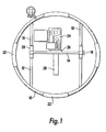
- the camera rig 40 is shown in use with a camera 42 in Fig 3 .
- the camera 42 being attached to the rig 40 via releasable engagement with support means 44.
Landscapes
- Engineering & Computer Science (AREA)
- General Engineering & Computer Science (AREA)
- Mechanical Engineering (AREA)
- Physics & Mathematics (AREA)
- General Physics & Mathematics (AREA)
- Accessories Of Cameras (AREA)
- Studio Devices (AREA)
- Camera Bodies And Camera Details Or Accessories (AREA)
- Endoscopes (AREA)
- Cameras In General (AREA)
- Transmission And Conversion Of Sensor Element Output (AREA)
Abstract
Description
- The present invention relates to a camera rig, and particularly although not necessarily exclusively relates to a camera rig for use with a digital video camera.
- Digital video cameras have become very popular due to their inherent advantages. These advantages include being able to download the shot film onto a personal computer. This allows the editing to be achieved easily and quickly.
- As digital video cameras have become more popular over the last few years they have, due to increased understanding and better technologies, become smaller. This offers the advantage that they are more easily transportable. However, there are a number of problems associated with small video cameras. One such problem is that it is difficult to shoot steady film. By film it is meant a series of images stored as a set of data. When film is taken by a camera that has not been supported it is usual to find that the resultant film shakes. This is due to the user moving the camera through the filming process. This phenomenon is generally termed camera shake.
- It is known to attach cameras to free standing supports, often termed tripods. Tripods allow the camera to be supported and hence allows ease of taking film without any resultant camera shake. However, the problem with a tripod arrangement is that it is not particularly mobile and hence the resultant drawbacks encountered when filming in a confined area, or when the cameraman is required to move when filming. It is therefore a general aim of the present invention to overcome or ameliorate the problem of camera shake whilst still giving the user of the camera the mobility to move the camera to different locations while filming.
- Digital video cameras are also fragile. In a busy working environment it is not uncommon for a camera to be dropped. Cameras are, in the main, not very robust and hence damage can often be incurred following it being dropped. Therefore the present invention also seeks to provide means to prevent damage should the camera be inadvertently dropped. The present invention particularly seeks to overcome the problem of damage to a camera through dropping or accident when the camera is not mounted on a tripod.
- Digital video cameras also have further inherent disadvantages. These include the need for a user, if reasonable film is to be taken, to devote both hands to the camera. Therefore if other accessories are required, such as a microphone or a light source a second person is required. Alternatively the cameraman must attempt to use both pieces of equipment simultaneously. This causes poor film quality. The present invention attempts to provide a solution to this problem, whilst still attempting to overcome the disadvantages of a tripod arrangement.
- The present invention aims to address to the above problem by providing a camera rig which is capable of securely holding a camera and preferably one or more ancillary devices, and that in use or transport is easily moved.
- Equipment for filming and photography is in the main expensive. Therefore it is also a preferred aim of the present invention to provide a cost effective frame structure that may be easily manufactured, whilst being robust that solves the above problems.
-
US 3,650,195 discloses a flash adapter for cameras comprising a frame with outer and inner rings and a camera support means. - According to the present invention, there is provided, a camera rig for hand held use comprising a frame comprising an outer frame and an inner frame mounted inside the outer frame, a camera support means provided on the inner frame, wherein the outer frame surrounds the camera support means and characterised in that the outer frame comprises at least two grip portions spaced apart from one another to opposite sides of the camera support means such that, in use, a user may hold the camera rig by gripping only said grip portions, and the camera support means is provided on a middle bar of the inner frame and wherein the rig comprises a handle portion provided to engage an opposite side of the middle bar directly opposite to the camera support means.
- Optional features of the invention are set out in the claims.
- In order that the present invention be more readily understood specific embodiments thereof will now be described with reference to the accompanying drawings in which,
-
Fig 1 shows a front view of a first embodiment of a camera rig in accordance with the present invention; and -
Fig 2 shows a front view of a second embodiment of a camera rig; and -
Fig 3 shows a front view of the second embodiment in use. - Referring to the drawings, and in particular
Fig. 1 a camera rig comprises acircular frame 10. AnH frame 12, having two uprightouter bars 16 with amiddle bar 14 extending between them, is affixed inside thecircular frame 10. Themiddle bar 14 of theH frame 12 is moveable along the twoouter bars 16. Each end of themiddle bar 14 is fitted with aslider 20. The sliders are adapted to fit around theouter bar 16 and hence the middle bar is capable of moving along the outer bars. One of thesliders 20 comprises ameans 18 that allows the middle bar to be secured in any position along theouter bars 16. The securing means may typically be a screw fixing. - The sliders comprise Teflon inserts to reduce friction between the sliders and
outer bars 16. - The circular frame comprises a plurality of
grip portions 22 that aid in both alignment and ease of use. Usually thegrip portions 22 will comprise rubber, however any similar material will suffice. In this example four such grip portions are provided, spaced equally around the circular frame. - In use a
camera 24 is releasably secured to the middle bar via support means 26. The position of the middle bar may then be adjusted according to the desired camera position. The moveable central bar also allows cameras of different sizes to be secured to the frame. - A
handle 28 is attached to the side of themiddle bar 14 remote from the securing means. Thehandle 28 allows a user to grip same for convenient attachment and removal of thecamera 24 from the support means 26. - A user may then, free of the restraints of a tripod or other fixed support device, film quickly and steadily from a variety of locations.
- It will also be appreciated that the circular frame offers protection to the camera against damage. Such protection is of great advantage considering the costs of cameras, and digital video cameras in particular.
- Accessories, such as a microphone or light source, may be conveniently attached to the circular frame, thus allowing a user to carry all items together. This has numerous advantages, including that only one person is needed to perform the task and also that the various pieces of equipment can be positioned together.
- In
Fig 2 a second embodiment of acamera rig 40 is depicted wherein acircular frame 30 possesses an internal H frame 32. The H frame 32 is devoid of downwardly extending outer bars from themiddle bar 34 of the frame 32. In this second embodiment the H frame 32 is attached to thecircular frame 30 at each end of themiddle bar 34 and at the end of the upwardly extendingouter bars 36. This forms a fixed rigidframe camera rig 40. - This
camera rig 40 is equipped with two pairs ofgrip portions 38, each pair being present on opposite portions of thecircular frame 30. - The
camera rig 40 is shown in use with acamera 42 inFig 3 . Thecamera 42 being attached to therig 40 via releasable engagement with support means 44. - It is to be understood that the above described specific embodiments are described by way of example only and that many variations or modifications are possible.
Claims (8)
- A camera rig for hand held use comprising
a frame (10) comprising an outer frame and an inner frame mounted inside the outer frame
a camera support means (26, 44) provided on the inner frame, wherein the outer frame (10) surrounds the camera support means (26, 44) and
characterised in that the outer frame comprises at least two grip portions spaced apart from one another to opposite sides of the camera support means (26, 44) such that, in use, a user may hold the camera rig by gripping only said grip portions, and the camera support means is provided on a middle bar of the inner frame and wherein the rig comprises a handle portion (28) provided to engage an opposite side of the middle bar directly opposite to the camera support means. - A camera rig according to claim 1, wherein the outer frame is substantially circular or substantially elliptical.
- A camera rig according to claim 1, wherein at least a part of the inner frame is movable with respect to the remainder of the frame (10).
- A camera rig according to claim 1, wherein the inner frame comprises an H frame.
- A camera rig according to claim 4, wherein the centre bar of the H frame is capable of movement with respect to the remainder of the frame.
- A camera rig according to any preceding claim, wherein the frame (10) is made from aluminium.
- A camera rig according to any preceding claim, wherein the camera support means (26, 44) is integral with the frame (10).
- A camera rig according to any preceding claim, wherein the frame (10) is configured to permit the attachment of at least one accessory.
Applications Claiming Priority (3)
| Application Number | Priority Date | Filing Date | Title |
|---|---|---|---|
| GBGB0103279.6A GB0103279D0 (en) | 2001-02-09 | 2001-02-09 | Camera Rig |
| GB0103279 | 2001-02-09 | ||
| PCT/GB2002/000594 WO2002065206A1 (en) | 2001-02-09 | 2002-02-11 | Camera rig |
Publications (2)
| Publication Number | Publication Date |
|---|---|
| EP1368704A1 EP1368704A1 (en) | 2003-12-10 |
| EP1368704B1 true EP1368704B1 (en) | 2011-06-22 |
Family
ID=9908460
Family Applications (1)
| Application Number | Title | Priority Date | Filing Date |
|---|---|---|---|
| EP02711061A Expired - Lifetime EP1368704B1 (en) | 2001-02-09 | 2002-02-11 | Camera rig |
Country Status (7)
| Country | Link |
|---|---|
| US (1) | US7033088B2 (en) |
| EP (1) | EP1368704B1 (en) |
| JP (1) | JP4163956B2 (en) |
| CN (1) | CN100549803C (en) |
| AT (1) | ATE514121T1 (en) |
| GB (1) | GB0103279D0 (en) |
| WO (1) | WO2002065206A1 (en) |
Families Citing this family (12)
| Publication number | Priority date | Publication date | Assignee | Title |
|---|---|---|---|---|
| JP4738946B2 (en) * | 2005-09-12 | 2011-08-03 | キヤノン株式会社 | Imaging device |
| DE102006036126A1 (en) * | 2006-08-01 | 2008-02-07 | Ulisse Foddis | Camera device |
| US20090028541A1 (en) * | 2006-09-18 | 2009-01-29 | Livitz Alexandr V | Movable flash adapter |
| GB2454889A (en) * | 2007-11-22 | 2009-05-27 | Jon Lucas | Apparatus for receiving and protecting a camcorder |
| EP2499416A4 (en) * | 2009-11-13 | 2016-04-20 | Garrett W Brown | Extendable camera support and stablization apparatus |
| US20120285909A1 (en) * | 2011-05-10 | 2012-11-15 | M. Klemme Technology, Corp. | Bracket for camera and accessories |
| US20160227080A1 (en) * | 2013-02-25 | 2016-08-04 | iOgrapher, LLC | Apparatus for different sized mobile devices that perform image capture |
| US9002187B1 (en) * | 2014-10-02 | 2015-04-07 | Patricia L Reiman | Handheld subject framing apparatus for photograph |
| JP2017120333A (en) * | 2015-12-28 | 2017-07-06 | ソニー株式会社 | Camera accessories and imaging unit |
| CN207112322U (en) * | 2017-04-21 | 2018-03-16 | 深圳市大疆灵眸科技有限公司 | Head support |
| US20200088400A1 (en) * | 2019-11-20 | 2020-03-19 | Shenzhen Youbaise Technology Co., Ltd. | Fill light applied to live streaming of mobile phone |
| JP2021103268A (en) * | 2019-12-25 | 2021-07-15 | 株式会社リコー | Support device and imaging apparatus |
Citations (2)
| Publication number | Priority date | Publication date | Assignee | Title |
|---|---|---|---|---|
| US3550519A (en) * | 1968-07-05 | 1970-12-29 | Edward H Lewis | Multiple-light bar for portable camera |
| US3650195A (en) * | 1967-04-25 | 1972-03-21 | Richard B Jones | Flash adapter for press camera |
Family Cites Families (8)
| Publication number | Priority date | Publication date | Assignee | Title |
|---|---|---|---|---|
| DE1026622B (en) * | 1956-07-17 | 1958-03-20 | Kurt Bertrams | Camera and light carrier |
| US3893145A (en) * | 1974-04-19 | 1975-07-01 | Dwayne L King | Flash extender and camera support |
| DE7626864U1 (en) * | 1976-08-27 | 1976-12-23 | Rollei-Werke Franke & Heidecke, 3300 Braunschweig | CAMERA WITH QUICK FOCUS HANDLE |
| US4272177A (en) * | 1980-05-27 | 1981-06-09 | Ottenheimer Charles J | Multiple camera mounting bracket |
| US4727390A (en) * | 1987-06-22 | 1988-02-23 | Brown Melvin W | Camera mounting bracket |
| CN2066594U (en) * | 1990-05-23 | 1990-11-28 | 钱玉春 | Multifunctional miniature tripod for camera |
| US5389987A (en) * | 1993-07-30 | 1995-02-14 | Corbeil; Gilles D. G. | Motion translation device for positioning cameras and other aimed instruments |
| US5890025A (en) | 1997-06-03 | 1999-03-30 | Hart Productions, Inc. | Frame assembly for supporting a camera |
-
2001
- 2001-02-09 GB GBGB0103279.6A patent/GB0103279D0/en not_active Ceased
-
2002
- 2002-02-11 AT AT02711061T patent/ATE514121T1/en not_active IP Right Cessation
- 2002-02-11 WO PCT/GB2002/000594 patent/WO2002065206A1/en not_active Ceased
- 2002-02-11 EP EP02711061A patent/EP1368704B1/en not_active Expired - Lifetime
- 2002-02-11 CN CNB02804780XA patent/CN100549803C/en not_active Expired - Fee Related
- 2002-02-11 US US10/470,739 patent/US7033088B2/en not_active Expired - Fee Related
- 2002-02-11 JP JP2002564664A patent/JP4163956B2/en not_active Expired - Fee Related
Patent Citations (2)
| Publication number | Priority date | Publication date | Assignee | Title |
|---|---|---|---|---|
| US3650195A (en) * | 1967-04-25 | 1972-03-21 | Richard B Jones | Flash adapter for press camera |
| US3550519A (en) * | 1968-07-05 | 1970-12-29 | Edward H Lewis | Multiple-light bar for portable camera |
Also Published As
| Publication number | Publication date |
|---|---|
| CN1491372A (en) | 2004-04-21 |
| EP1368704A1 (en) | 2003-12-10 |
| CN100549803C (en) | 2009-10-14 |
| JP2004520619A (en) | 2004-07-08 |
| JP4163956B2 (en) | 2008-10-08 |
| GB0103279D0 (en) | 2001-03-28 |
| US20040096208A1 (en) | 2004-05-20 |
| US7033088B2 (en) | 2006-04-25 |
| ATE514121T1 (en) | 2011-07-15 |
| WO2002065206A1 (en) | 2002-08-22 |
Similar Documents
| Publication | Publication Date | Title |
|---|---|---|
| JP4507612B2 (en) | Tripod handle device | |
| TWI509182B (en) | Stable mounting frame and method for smoothly supporting motion sensitive image capturing device | |
| US6439515B1 (en) | Video camera support device | |
| US20180088445A1 (en) | Cell Phone Case with Extendable Remote Camera Control | |
| US20100200710A1 (en) | Compact camera stand | |
| US20060257138A1 (en) | Apparatus for supporting a camera | |
| CN103968203A (en) | Trigger actuated clamp for smart phone camera | |
| US7033088B2 (en) | Camera rig | |
| JP2018515798A (en) | Integrated expansion and mechanical protection system for portable digital devices | |
| KR102042136B1 (en) | Wearable holder for photographic equipment | |
| US11042077B2 (en) | Gimbal supporting frame | |
| US7766562B2 (en) | Support cradle and strap for large camera lens | |
| JP2004520619A6 (en) | Camera tools | |
| JP2005142671A (en) | Stand for mobile communication terminal | |
| KR101899104B1 (en) | Selfie Stick | |
| US20080310834A1 (en) | Camera Holding Device | |
| JP4778110B2 (en) | Tools and systems for fixing mobile devices with video recording functions such as video cameras or smartphones to the shoulders and flat surfaces | |
| WO2017014227A1 (en) | Case for mobile communication terminal | |
| KR101957928B1 (en) | a holder for small type camera | |
| KR101959654B1 (en) | Fixed frame | |
| US4693575A (en) | Camera support | |
| JPH084986A (en) | Tripod for multi-functioning camera | |
| KR200478352Y1 (en) | Apparatus of photograph aid and holding for mobile phone | |
| CN213512772U (en) | Bracket assembly | |
| KR102355674B1 (en) | Selfie stick |
Legal Events
| Date | Code | Title | Description |
|---|---|---|---|
| PUAI | Public reference made under article 153(3) epc to a published international application that has entered the european phase |
Free format text: ORIGINAL CODE: 0009012 |
|
| 17P | Request for examination filed |
Effective date: 20030905 |
|
| AK | Designated contracting states |
Kind code of ref document: A1 Designated state(s): AT BE CH CY DE DK ES FI FR GB GR IE IT LI LU MC NL PT SE TR |
|
| AX | Request for extension of the european patent |
Extension state: AL LT LV MK RO SI |
|
| 17Q | First examination report despatched |
Effective date: 20040907 |
|
| 17Q | First examination report despatched |
Effective date: 20040907 |
|
| RAP1 | Party data changed (applicant data changed or rights of an application transferred) |
Owner name: RED MULLET LIMITED |
|
| GRAC | Information related to communication of intention to grant a patent modified |
Free format text: ORIGINAL CODE: EPIDOSCIGR1 |
|
| GRAP | Despatch of communication of intention to grant a patent |
Free format text: ORIGINAL CODE: EPIDOSNIGR1 |
|
| GRAS | Grant fee paid |
Free format text: ORIGINAL CODE: EPIDOSNIGR3 |
|
| GRAA | (expected) grant |
Free format text: ORIGINAL CODE: 0009210 |
|
| AK | Designated contracting states |
Kind code of ref document: B1 Designated state(s): AT BE CH CY DE DK ES FI FR GB GR IE IT LI LU MC NL PT SE TR |
|
| REG | Reference to a national code |
Ref country code: GB Ref legal event code: FG4D |
|
| REG | Reference to a national code |
Ref country code: CH Ref legal event code: EP |
|
| REG | Reference to a national code |
Ref country code: IE Ref legal event code: FG4D |
|
| REG | Reference to a national code |
Ref country code: DE Ref legal event code: R096 Ref document number: 60240334 Country of ref document: DE Effective date: 20110804 |
|
| REG | Reference to a national code |
Ref country code: NL Ref legal event code: VDEP Effective date: 20110622 |
|
| PG25 | Lapsed in a contracting state [announced via postgrant information from national office to epo] |
Ref country code: SE Free format text: LAPSE BECAUSE OF FAILURE TO SUBMIT A TRANSLATION OF THE DESCRIPTION OR TO PAY THE FEE WITHIN THE PRESCRIBED TIME-LIMIT Effective date: 20110622 |
|
| REG | Reference to a national code |
Ref country code: DE Ref legal event code: R082 Ref document number: 60240334 Country of ref document: DE Representative=s name: OLSWANG GERMANY LLP, DE |
|
| PG25 | Lapsed in a contracting state [announced via postgrant information from national office to epo] |
Ref country code: CY Free format text: LAPSE BECAUSE OF FAILURE TO SUBMIT A TRANSLATION OF THE DESCRIPTION OR TO PAY THE FEE WITHIN THE PRESCRIBED TIME-LIMIT Effective date: 20110622 Ref country code: FI Free format text: LAPSE BECAUSE OF FAILURE TO SUBMIT A TRANSLATION OF THE DESCRIPTION OR TO PAY THE FEE WITHIN THE PRESCRIBED TIME-LIMIT Effective date: 20110622 Ref country code: GR Free format text: LAPSE BECAUSE OF FAILURE TO SUBMIT A TRANSLATION OF THE DESCRIPTION OR TO PAY THE FEE WITHIN THE PRESCRIBED TIME-LIMIT Effective date: 20110923 Ref country code: AT Free format text: LAPSE BECAUSE OF FAILURE TO SUBMIT A TRANSLATION OF THE DESCRIPTION OR TO PAY THE FEE WITHIN THE PRESCRIBED TIME-LIMIT Effective date: 20110622 |
|
| PG25 | Lapsed in a contracting state [announced via postgrant information from national office to epo] |
Ref country code: NL Free format text: LAPSE BECAUSE OF FAILURE TO SUBMIT A TRANSLATION OF THE DESCRIPTION OR TO PAY THE FEE WITHIN THE PRESCRIBED TIME-LIMIT Effective date: 20110622 Ref country code: BE Free format text: LAPSE BECAUSE OF FAILURE TO SUBMIT A TRANSLATION OF THE DESCRIPTION OR TO PAY THE FEE WITHIN THE PRESCRIBED TIME-LIMIT Effective date: 20110622 |
|
| PG25 | Lapsed in a contracting state [announced via postgrant information from national office to epo] |
Ref country code: PT Free format text: LAPSE BECAUSE OF FAILURE TO SUBMIT A TRANSLATION OF THE DESCRIPTION OR TO PAY THE FEE WITHIN THE PRESCRIBED TIME-LIMIT Effective date: 20111024 |
|
| PLBE | No opposition filed within time limit |
Free format text: ORIGINAL CODE: 0009261 |
|
| STAA | Information on the status of an ep patent application or granted ep patent |
Free format text: STATUS: NO OPPOSITION FILED WITHIN TIME LIMIT |
|
| 26N | No opposition filed |
Effective date: 20120323 |
|
| PG25 | Lapsed in a contracting state [announced via postgrant information from national office to epo] |
Ref country code: DK Free format text: LAPSE BECAUSE OF FAILURE TO SUBMIT A TRANSLATION OF THE DESCRIPTION OR TO PAY THE FEE WITHIN THE PRESCRIBED TIME-LIMIT Effective date: 20110622 |
|
| REG | Reference to a national code |
Ref country code: DE Ref legal event code: R097 Ref document number: 60240334 Country of ref document: DE Effective date: 20120323 |
|
| PG25 | Lapsed in a contracting state [announced via postgrant information from national office to epo] |
Ref country code: MC Free format text: LAPSE BECAUSE OF NON-PAYMENT OF DUE FEES Effective date: 20120229 |
|
| REG | Reference to a national code |
Ref country code: CH Ref legal event code: PL |
|
| PG25 | Lapsed in a contracting state [announced via postgrant information from national office to epo] |
Ref country code: LI Free format text: LAPSE BECAUSE OF NON-PAYMENT OF DUE FEES Effective date: 20120229 Ref country code: CH Free format text: LAPSE BECAUSE OF NON-PAYMENT OF DUE FEES Effective date: 20120229 |
|
| REG | Reference to a national code |
Ref country code: IE Ref legal event code: MM4A |
|
| PG25 | Lapsed in a contracting state [announced via postgrant information from national office to epo] |
Ref country code: IE Free format text: LAPSE BECAUSE OF NON-PAYMENT OF DUE FEES Effective date: 20120211 |
|
| PG25 | Lapsed in a contracting state [announced via postgrant information from national office to epo] |
Ref country code: ES Free format text: LAPSE BECAUSE OF FAILURE TO SUBMIT A TRANSLATION OF THE DESCRIPTION OR TO PAY THE FEE WITHIN THE PRESCRIBED TIME-LIMIT Effective date: 20111003 |
|
| PG25 | Lapsed in a contracting state [announced via postgrant information from national office to epo] |
Ref country code: TR Free format text: LAPSE BECAUSE OF FAILURE TO SUBMIT A TRANSLATION OF THE DESCRIPTION OR TO PAY THE FEE WITHIN THE PRESCRIBED TIME-LIMIT Effective date: 20110622 |
|
| PG25 | Lapsed in a contracting state [announced via postgrant information from national office to epo] |
Ref country code: LU Free format text: LAPSE BECAUSE OF NON-PAYMENT OF DUE FEES Effective date: 20120211 |
|
| REG | Reference to a national code |
Ref country code: FR Ref legal event code: PLFP Year of fee payment: 14 |
|
| PGFP | Annual fee paid to national office [announced via postgrant information from national office to epo] |
Ref country code: IT Payment date: 20150220 Year of fee payment: 14 Ref country code: DE Payment date: 20150226 Year of fee payment: 14 |
|
| PGFP | Annual fee paid to national office [announced via postgrant information from national office to epo] |
Ref country code: FR Payment date: 20150217 Year of fee payment: 14 Ref country code: GB Payment date: 20150226 Year of fee payment: 14 |
|
| REG | Reference to a national code |
Ref country code: DE Ref legal event code: R119 Ref document number: 60240334 Country of ref document: DE |
|
| GBPC | Gb: european patent ceased through non-payment of renewal fee |
Effective date: 20160211 |
|
| REG | Reference to a national code |
Ref country code: FR Ref legal event code: ST Effective date: 20161028 |
|
| PG25 | Lapsed in a contracting state [announced via postgrant information from national office to epo] |
Ref country code: IT Free format text: LAPSE BECAUSE OF NON-PAYMENT OF DUE FEES Effective date: 20160211 |
|
| PG25 | Lapsed in a contracting state [announced via postgrant information from national office to epo] |
Ref country code: DE Free format text: LAPSE BECAUSE OF NON-PAYMENT OF DUE FEES Effective date: 20160901 Ref country code: GB Free format text: LAPSE BECAUSE OF NON-PAYMENT OF DUE FEES Effective date: 20160211 Ref country code: FR Free format text: LAPSE BECAUSE OF NON-PAYMENT OF DUE FEES Effective date: 20160229 |