EP1368532B1 - Pipe system for receiving and transporting lime sludge from a white liquor filter - Google Patents
Pipe system for receiving and transporting lime sludge from a white liquor filter Download PDFInfo
- Publication number
- EP1368532B1 EP1368532B1 EP02711584A EP02711584A EP1368532B1 EP 1368532 B1 EP1368532 B1 EP 1368532B1 EP 02711584 A EP02711584 A EP 02711584A EP 02711584 A EP02711584 A EP 02711584A EP 1368532 B1 EP1368532 B1 EP 1368532B1
- Authority
- EP
- European Patent Office
- Prior art keywords
- pipe system
- lime sludge
- section
- flow cross
- filter
- Prior art date
- Legal status (The legal status is an assumption and is not a legal conclusion. Google has not performed a legal analysis and makes no representation as to the accuracy of the status listed.)
- Expired - Lifetime
Links
- 239000010802 sludge Substances 0.000 title claims abstract description 84
- 235000008733 Citrus aurantifolia Nutrition 0.000 title claims abstract description 83
- 235000011941 Tilia x europaea Nutrition 0.000 title claims abstract description 83
- 239000004571 lime Substances 0.000 title claims abstract description 83
- 238000004062 sedimentation Methods 0.000 claims abstract description 13
- 238000000034 method Methods 0.000 claims abstract description 10
- 230000008569 process Effects 0.000 claims abstract description 9
- 238000009993 causticizing Methods 0.000 claims abstract description 5
- 239000007788 liquid Substances 0.000 claims description 15
- 230000001105 regulatory effect Effects 0.000 claims description 13
- 238000010790 dilution Methods 0.000 claims description 7
- 239000012895 dilution Substances 0.000 claims description 7
- 230000000630 rising effect Effects 0.000 claims description 7
- XLYOFNOQVPJJNP-UHFFFAOYSA-N water Substances O XLYOFNOQVPJJNP-UHFFFAOYSA-N 0.000 claims description 3
- 230000007704 transition Effects 0.000 claims description 2
- 238000001914 filtration Methods 0.000 description 8
- 238000004140 cleaning Methods 0.000 description 6
- ODINCKMPIJJUCX-UHFFFAOYSA-N Calcium oxide Chemical compound [Ca]=O ODINCKMPIJJUCX-UHFFFAOYSA-N 0.000 description 4
- HEMHJVSKTPXQMS-UHFFFAOYSA-M Sodium hydroxide Chemical compound [OH-].[Na+] HEMHJVSKTPXQMS-UHFFFAOYSA-M 0.000 description 3
- 239000012065 filter cake Substances 0.000 description 3
- 238000009434 installation Methods 0.000 description 3
- 239000000463 material Substances 0.000 description 3
- 239000000243 solution Substances 0.000 description 3
- VTYYLEPIZMXCLO-UHFFFAOYSA-L Calcium carbonate Chemical compound [Ca+2].[O-]C([O-])=O VTYYLEPIZMXCLO-UHFFFAOYSA-L 0.000 description 2
- CDBYLPFSWZWCQE-UHFFFAOYSA-L Sodium Carbonate Chemical compound [Na+].[Na+].[O-]C([O-])=O CDBYLPFSWZWCQE-UHFFFAOYSA-L 0.000 description 2
- 230000001070 adhesive effect Effects 0.000 description 2
- 238000013019 agitation Methods 0.000 description 2
- 230000004075 alteration Effects 0.000 description 2
- 239000000292 calcium oxide Substances 0.000 description 2
- 235000012255 calcium oxide Nutrition 0.000 description 2
- 239000000203 mixture Substances 0.000 description 2
- 238000011144 upstream manufacturing Methods 0.000 description 2
- QAOWNCQODCNURD-UHFFFAOYSA-L Sulfate Chemical compound [O-]S([O-])(=O)=O QAOWNCQODCNURD-UHFFFAOYSA-L 0.000 description 1
- 230000035508 accumulation Effects 0.000 description 1
- 238000009825 accumulation Methods 0.000 description 1
- 230000001154 acute effect Effects 0.000 description 1
- 239000000853 adhesive Substances 0.000 description 1
- 238000010009 beating Methods 0.000 description 1
- 238000007664 blowing Methods 0.000 description 1
- 229910000019 calcium carbonate Inorganic materials 0.000 description 1
- 238000010411 cooking Methods 0.000 description 1
- 238000006073 displacement reaction Methods 0.000 description 1
- 239000004744 fabric Substances 0.000 description 1
- 239000011796 hollow space material Substances 0.000 description 1
- 239000006194 liquid suspension Substances 0.000 description 1
- 238000012986 modification Methods 0.000 description 1
- 230000004048 modification Effects 0.000 description 1
- 238000012856 packing Methods 0.000 description 1
- 238000000926 separation method Methods 0.000 description 1
- 239000002002 slurry Substances 0.000 description 1
- 229910000029 sodium carbonate Inorganic materials 0.000 description 1
- 239000000126 substance Substances 0.000 description 1
- 229910021653 sulphate ion Inorganic materials 0.000 description 1
- 238000002604 ultrasonography Methods 0.000 description 1
- 239000002023 wood Substances 0.000 description 1
Images

Classifications
-
- D—TEXTILES; PAPER
- D21—PAPER-MAKING; PRODUCTION OF CELLULOSE
- D21C—PRODUCTION OF CELLULOSE BY REMOVING NON-CELLULOSE SUBSTANCES FROM CELLULOSE-CONTAINING MATERIALS; REGENERATION OF PULPING LIQUORS; APPARATUS THEREFOR
- D21C11/00—Regeneration of pulp liquors or effluent waste waters
- D21C11/04—Regeneration of pulp liquors or effluent waste waters of alkali lye
-
- B—PERFORMING OPERATIONS; TRANSPORTING
- B01—PHYSICAL OR CHEMICAL PROCESSES OR APPARATUS IN GENERAL
- B01D—SEPARATION
- B01D33/00—Filters with filtering elements which move during the filtering operation
- B01D33/15—Filters with filtering elements which move during the filtering operation with rotary plane filtering surfaces
- B01D33/21—Filters with filtering elements which move during the filtering operation with rotary plane filtering surfaces with hollow filtering discs transversely mounted on a hollow rotary shaft
-
- B—PERFORMING OPERATIONS; TRANSPORTING
- B01—PHYSICAL OR CHEMICAL PROCESSES OR APPARATUS IN GENERAL
- B01D—SEPARATION
- B01D33/00—Filters with filtering elements which move during the filtering operation
- B01D33/44—Regenerating the filter material in the filter
- B01D33/46—Regenerating the filter material in the filter by scrapers, brushes nozzles or the like acting on the cake-side of the filtering element
- B01D33/463—Regenerating the filter material in the filter by scrapers, brushes nozzles or the like acting on the cake-side of the filtering element nozzles
-
- B—PERFORMING OPERATIONS; TRANSPORTING
- B01—PHYSICAL OR CHEMICAL PROCESSES OR APPARATUS IN GENERAL
- B01D—SEPARATION
- B01D33/00—Filters with filtering elements which move during the filtering operation
- B01D33/44—Regenerating the filter material in the filter
- B01D33/46—Regenerating the filter material in the filter by scrapers, brushes nozzles or the like acting on the cake-side of the filtering element
- B01D33/466—Regenerating the filter material in the filter by scrapers, brushes nozzles or the like acting on the cake-side of the filtering element scrapers
-
- B—PERFORMING OPERATIONS; TRANSPORTING
- B01—PHYSICAL OR CHEMICAL PROCESSES OR APPARATUS IN GENERAL
- B01D—SEPARATION
- B01D33/00—Filters with filtering elements which move during the filtering operation
- B01D33/70—Filters with filtering elements which move during the filtering operation having feed or discharge devices
- B01D33/76—Filters with filtering elements which move during the filtering operation having feed or discharge devices for discharging the filter cake, e.g. chutes
-
- Y—GENERAL TAGGING OF NEW TECHNOLOGICAL DEVELOPMENTS; GENERAL TAGGING OF CROSS-SECTIONAL TECHNOLOGIES SPANNING OVER SEVERAL SECTIONS OF THE IPC; TECHNICAL SUBJECTS COVERED BY FORMER USPC CROSS-REFERENCE ART COLLECTIONS [XRACs] AND DIGESTS
- Y02—TECHNOLOGIES OR APPLICATIONS FOR MITIGATION OR ADAPTATION AGAINST CLIMATE CHANGE
- Y02P—CLIMATE CHANGE MITIGATION TECHNOLOGIES IN THE PRODUCTION OR PROCESSING OF GOODS
- Y02P40/00—Technologies relating to the processing of minerals
- Y02P40/40—Production or processing of lime, e.g. limestone regeneration of lime in pulp and sugar mills
-
- Y—GENERAL TAGGING OF NEW TECHNOLOGICAL DEVELOPMENTS; GENERAL TAGGING OF CROSS-SECTIONAL TECHNOLOGIES SPANNING OVER SEVERAL SECTIONS OF THE IPC; TECHNICAL SUBJECTS COVERED BY FORMER USPC CROSS-REFERENCE ART COLLECTIONS [XRACs] AND DIGESTS
- Y10—TECHNICAL SUBJECTS COVERED BY FORMER USPC
- Y10S—TECHNICAL SUBJECTS COVERED BY FORMER USPC CROSS-REFERENCE ART COLLECTIONS [XRACs] AND DIGESTS
- Y10S210/00—Liquid purification or separation
- Y10S210/928—Paper mill waste, e.g. white water, black liquor treated
Definitions
- the invention relates to a pipe system for receiving and transporting lime sludge and mud from a filter medium in a continuously operating filter in a causticizing process, in which white liquor is separated from the lime sludge.
- the green liquor entering the causticizing process consists fundamentally of sodium carbonate.
- the green liquor is made to react with burnt lime, calcium carbonate (lime sludge) and sodium hydroxide (white liquor) being formed.
- the white liquor is filtered off in tube filters or disc filters, the latter in particular usually being of the pressurized type, after which the white liquor is reused in the sulphate process for cooking pulp wood chips.
- the lime sludge obtained from filtration is burnt so as to form burnt lime again.
- the cleaning of ducts through which adhesive substances are transported can be effected by, for example, manual cleaning or automatic cleaning.
- Manual cleaning has many obvious drawbacks such as operational stoppages or partial operational stoppages and a poor working environment.
- Automatic cleaning can be performed using well-known methods such as, for example, with brushes, beating tools, ultrasound, steam-jetting, and liquid application where this is possible.
- this arrangement is illustrated in the form of a level-regulated storage tank, in which there is a mechanical agitator.
- Some embodiments of this process comprise a sloping collecting pipe after the feed-out chutes, which collecting pipe leads to the storage tank.
- the lime sludge slurry is circulated from the bottom of the storage tank to the highest point of the sloping collecting pipe.
- the cost can be in the order of SEK 1,500,000 (approximately US$ 200,000).
- One object of the invention is to provide a system for receiving and transporting lime sludge from a filter medium in a continuously operating pressurized filter in a causticizing process, in which white liquor is separated from the lime sludge, and in which the system can be minimized in terms of size and cost at the same time as the conventionally used mechanical agitators can be dispensed with entirely, notwithstanding the strong tendency of the lime sludge to adhere to the walls in the handling system.
- Another object is to obtain a system in which the dry content can be kept high in the system, which high dry content has not been considered possible in the large storage tanks as the lime sludge is to be kept in a uniform solution throughout the storage tank.
- the total quantities to be handled are then smaller, which results in considerable savings on pipeline systems and associated equipment.
- Another object is to permit structural alterations in existing installations in which the available space is limited, it being possible then to arrange high-performance filter equipment in a small available space.
- the risk of sedimentation in the system is reduced by using forced recirculation which affords an increased speed throughout the volume of the lime sludge mixture received.
- a modified recirculation principle can be used in order to keep all the receiving chutes free from accumulations of lime sludge without having to dilute the lime sludge further with dilution liquid:
- the storage tank can be minimized or eliminated completely.
- a pressurized white liquid filter according to the invention is shown in Figure 1 and in cross section in Figure 2 .
- the pressurized filter vessel 1 is fed with unfiltered liquid in the form of white liquor mixed with lime sludge via the inlet 8.
- the unfiltered liquid forms a liquid level inside the filter which reaches a level just below the shaft 5 of the filter, and not above the inlet opening of a receiving chute for the lime sludge, which is described below.
- disc-shaped filter elements 2 Arranged on the shaft is a number of disc-shaped filter elements 2 which are each covered with a filter medium, in most cases in the form of a fine-meshed cloth.
- the filter consists of at least two discs covered with filter medium and arranged on a hollow rotating shaft. In certain applications, as many as fourteen discs may be used.
- Figure 1 shows 3 discs, one of which is concealed.
- White liquor is separated from the lime sludge by withdrawal through the filter medium of the disc filter element and is conveyed out of the filter via the hollow shaft, each disc filter element comprising stripping means interacting with the filter medium for freeing lime sludge accumulated on the filter medium, and a receiving chute being arranged with a receiving opening under each stripping means, and between two discs, so that each receiving opening collects lime sludge from two filter surfaces.
- the white liquor is separated during filtration through the filter medium and is conducted via the inside of the filter element down to the hollow shaft 5 and onward to the gas separation vessel 6.
- the hollow shaft 5 can preferably be divided into sections, so that the hollow space in the shaft is made up of cake-slice-shaped spaces, seen in cross section through the axis.
- a blower 7 is connected to the top of the vessel 6 and conducts gas back to the filter vessel 1 for pressurization of the process. Agitation (not shown) of unfiltered liquid also takes place in the filter for the purpose of preventing sedimentation.
- the agitation can be effected by means of, for example, blowing in air or liquid, and with or without ejectors.
- the shaft 5 is rotated continuously by a motor, a deposit of lime sludge being built up gradually on the filter medium as the white liquor passes through the filter medium.
- the filter normally operates with a precoat layer which is maintained intact during the majority of the operating time.
- the invention also functions on filters which operate without a precoat covering.
- the lime sludge which is deposited on the precoat or directly on the filter medium, is scraped off by a knife 3 (doctor) which is arranged above the level of the unfiltered liquid, and it then drops down into a receiving chute 4 which likewise has its opening above the level of the unfiltered liquid.
- a knife 3 doctor
- nozzles for dilution liquid 10 which dilute the stripped dry lime sludge to a dry content of at least 15%, preferably more than 20%, and typically in the range 25-30%. Dilution makes it possible to counteract to a certain extent clogging of the receiving chute.
- the receiving chute opens, via a sloping collecting pipe, in a storage vessel of considerable volume, in which a mechanical agitator is also arranged, in most cases in the form of a motor-driven propeller, which is driven continuously so as to avoid sedimentation and therefore keep the lime sludge in solution.
- a certain amount of the lime sludge being mechanically agitated is recirculated to the collecting pipe in order that the latter does not become clogged by sedimented lime sludge.
- the storage vessel receiving the lime sludge is thus replaced by a pipe system 11 which is common to the receiving chutes 4 and has a flow cross section which maintains a good flow rate and in which there is no need for mechanical agitators.
- Each receiving chute has a flow cross section ⁇ 1 , hereinafter referred to as the first flow cross section.
- the pipe system is arranged below the filter vessel 1 and connected to the respective receiving chutes, so that these chutes lead to the lime sludge dropping down vertically through the receiving chutes, without deflections and with contact with the walls in the chute being minimized, and on down to the pipe system 11.
- the connecting portion of the pipe system, the collecting pipe, to which the receiving chutes 4 are connected, is arranged essentially parallel to the shaft 5 of the filter, but with its downstream end, seen in the feed-out direction of the lime sludge, slightly lower than its upstream end.
- This connecting portion of the pipe system preferably has a circular cross section with a flow cross section ⁇ 2 , hereinafter referred to as the second flow cross section.
- the pipe system is designed in such a manner that, from the connection of the receiving chutes to the feed-out opening 30 of the pipe system, it has a flow cross section which maintains a good flow rate in the lime sludge, so that sedimentation of the lime sludge does not occur.
- the connecting portion in the pipe system for the receiving chutes has the same diameter d 2 over its extent, but variants with gradually increasing diameter can be used as, from each new receiving chute connected, seen in the feed-out direction of the lime sludge, a flow of diluted lime sludge is added. In this way, a good high flow rate can be maintained, and sedimentation can be avoided.
- the connecting portion of the pipe system which preferably has a circular flow cross section ⁇ 2 , ends in a small downpipe 14 at its downstream end.
- the downpipe is suitably a vertically upright downpipe with a local increase in the flow area in the pipe system in the downpipe corresponding to the flow cross section ⁇ 3 ,
- the flow cross sections of the pipe system in other parts which other parts constitute at least 75%, preferably at least 90%, of the total length of the pipe system between its inlet and outlet, are preferably designed in such a manner that these other parts have a flow cross section which does not exceed the flow cross section ⁇ 2 .
- the total length of the downpipe, L 1 in the vertical direction is: L 1 ⁇ 2.0 • d 2 and L 1 ⁇ 1.5 • d 3 .
- the collecting pipe has a diameter of roughly 700 mm
- the downpipe has a diameter of roughly 900 mm
- the outlet has a diameter of roughly 200 mm.
- the height of the downpipe is suitably greater than its diameter, appropriately between 1800 and 2200 mm for a 900 mm diameter, and 1000 and 1500 for a 600 mm diameter.
- the collecting pipe and the outlet pipe can of course be made smaller, but with essentially the same proportions as in the case with 3 m discs.
- the pipe system does not have to have a circular cross section in all its parts, but can also have an oval or rectangular cross section.
- the lower part of the downpipe is designed with an essentially continuous conical transition from the third flow cross section ⁇ 3 of the downpipe to the fourth flow cross section ⁇ 4 in the feed-out opening which follows for the lime sludge received.
- a level meter 21 is suitably connected to the downpipe, which meter is in turn coupled to a regulating unit 22 which is finally connected to the regulating valve 20.
- the pump can be adjusted by, for example, either displacement regulation or speed regulation.
- the relationship between the third flow cross section ⁇ 3 in the downpipe and the second flow cross section ⁇ 2 of the collecting pipe is: ⁇ 3 ⁇ 4.5 • ⁇ 2 and preferably ⁇ 3 ⁇ 4 • ⁇ 2 .
- the relationship between the fourth flow cross section ⁇ 4 in the outlet and the second flow cross section ⁇ 2 is: ⁇ 4 ⁇ 0.3 • ⁇ 2 and preferably ⁇ 4 ⁇ 0.2 • ⁇ 2 2 • ⁇ 2 .
- a conventional recirculation system 12 is connected to the pipe system, the inlet 12a of the recirculation system being arranged after the connection of the last chute to the pipe system, seen in the feed-out direction of the lime sludge through the pipe system, and an outlet 12b being arranged in front of the connection of the first chute to the pipe system.
- a pump 12c is arranged in the recirculation system for recirculation of a part quantity of diluted lime sludge from its inlet to its outlet.
- the inlet 12a of the recirculation system is suitably arranged at the lowest point of the pipe system, which is after the level measuring tank 14 in the embodiment shown.
- the pump 12c preferably a sludge pump resistant to wearing material, is preferably driven continuously at constant speed during the majority of the operating time of the filter, the diluted lime sludge being kept in boosted circulation so that sedimentation is counteracted more effectively.
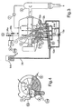
- FIG 3 shows a second variant of a pressurized white liquor filter according to the invention in cross section.
- the pipe system is adapted so that the counterpressure-generating means in the pipe system feed-out opening 30b of the pressure filter instead consists of a rising pipe which opens at a level above the level of the unfiltered white liquor mixed with lime sludge in the filter.
- the counterpressure-generating means in the pipe system feed-out opening 30b of the pressure filter instead consists of a rising pipe which opens at a level above the level of the unfiltered white liquor mixed with lime sludge in the filter.
- the level is instead measured in the receiving chutes 4a via a level meter 21b, the signal A from which is sent to a regulating unit 22b.
- the regulating unit acts on valves 26a/26b, by which the overpressure in the filter and thus the filtration flow through the filter can be regulated.
- the level 30b at which the lime sludge can be fed out in the variant with a rising pipe corresponds to a raised level relative to the level of the unfiltered liquid in the filter.
- the maximum raised level corresponds to the maximum pressure level inside the filter minus the pressure losses in the pipe system.
- a modified recirculation system 12 in Figure 3 is connected to the pipe system, the inlet 12a of the recirculation system being arranged after the connection of the last chute to the pipe system, seen in the feed-out direction of the lime sludge through the pipe system, and an outlet 12b being arranged in front of the connection of the first chute to the pipe system.
- a pump 12c is arranged in the recirculation system for recirculation of a part quantity of diluted lime sludge from its inlet to its outlet.
- the inlet 12a of the recirculation system is arranged at the lowest point of the pipe system, which is after the level measuring tank 14 in the embodiment shown.
- At least one second outlet 12e is also arranged so as to open in each receiving chute 4a at a level between its receiving opening 4 and its connection to the pipe system.
- Each outlet 12e is provided with recirculated diluted lime sludge via the branch 12 from the pressure side of the pump 12c. In this way, a boosted flow is obtained through the receiving chutes as well, as a result of which the risks of sedimentation and clogging in the receiving chutes are also reduced.
Landscapes
- Chemical & Material Sciences (AREA)
- Chemical Kinetics & Catalysis (AREA)
- Treatment Of Sludge (AREA)
- Physical Water Treatments (AREA)
Abstract
Description
- The invention relates to a pipe system for receiving and transporting lime sludge and mud from a filter medium in a continuously operating filter in a causticizing process, in which white liquor is separated from the lime sludge.
- The green liquor entering the causticizing process consists fundamentally of sodium carbonate. In the process, the green liquor is made to react with burnt lime, calcium carbonate (lime sludge) and sodium hydroxide (white liquor) being formed. The white liquor is filtered off in tube filters or disc filters, the latter in particular usually being of the pressurized type, after which the white liquor is reused in the sulphate process for cooking pulp wood chips. The lime sludge obtained from filtration is burnt so as to form burnt lime again.
- Modern effective filtration arrangements for white liquor filtration produce lime sludge/filter cakes with relatively high dry contents but in which the lime sludge cakes, after they have been removed from the filter medium, constitute a material with highly adhesive properties. The material of the lime sludge cakes therefore has a tendency to adhere to the inner walls in the chute(s) via which it is transported away from the filter medium. This can give rise to acute operational stoppages or stoppages for cleaning on account of clogging, which reduces the capacity of the filtration arrangements and can cause problems and lead to other disadvantages.
- The cleaning of ducts through which adhesive substances are transported can be effected by, for example, manual cleaning or automatic cleaning. Manual cleaning has many obvious drawbacks such as operational stoppages or partial operational stoppages and a poor working environment. Automatic cleaning can be performed using well-known methods such as, for example, with brushes, beating tools, ultrasound, steam-jetting, and liquid application where this is possible.
- In continuously operating filtration arrangements for liquid suspensions such as, for example, those described in
SE-C-463771 US 4,929,355 ), a filter cake in the form of lime sludge is formed on a filter medium. This lime sludge is scraped off by doctors (knives) and drops down into receiving chutes, in which further dilution by dilution liquid is essential for it to be possible to transport the lime sludge onward. In saidSE-C-463771 - A corresponding solution with a storage tank and mechanical mixer is disclosed in
US 5,151,176 . In other applications with tube filters as well (seeUS 4,264,445 ), use is made of a storage tank and a mechanical mixer in order for it to be possible to deal with the filter cake taken out of a pressurized tube filter. The bulky storage tank and the mechanical agitator arranged therein were considered necessary in order for it to be possible to keep the lime sludge well mixed with added dilution liquid and to prevent sedimentation of the lime sludge. - The known art has led to handling systems for the lime sludge being unnecessarily expensive and space-consuming. Conventionally employed treatment vessels with mechanical agitators for receiving the lime sludge resulted in considerable costs. In the case of application in a white liquor filter with a relatively low capacity of 2,500 m3/24 hrs, and a vessel with dimensions of 1900 x 2800 (diameter x height), the cost can be in the order of SEK 800,000 (approximately USS 100,000). In a white liquor filter with a higher capacity of 8,000 m3/24 hrs, and a vessel with dimensions of 2800 x 3300 (diameter x height), the cost can be in the order of SEK 1,500,000 (approximately US$ 200,000).
- Another disadvantage is that the mechanical agitators, in particular when applied in pressurized white liquor filters, have to be provided with packing boxes, which often lead to leakage problems.
- The space requirement for storage tanks also limits the possibilities of structural alterations in existing installations where available space does not always allow the storage tank to be positioned adjacent to the filter, or results in the filter and the storage tank having to be located on different floors in the installation. In most cases, the storage tanks used in white liquor filtration have been virtually the same size as the white liquor filter itself, which is in itself very space-consuming.
- One object of the invention is to provide a system for receiving and transporting lime sludge from a filter medium in a continuously operating pressurized filter in a causticizing process, in which white liquor is separated from the lime sludge, and in which the system can be minimized in terms of size and cost at the same time as the conventionally used mechanical agitators can be dispensed with entirely, notwithstanding the strong tendency of the lime sludge to adhere to the walls in the handling system.
- Another object is to obtain a system in which the dry content can be kept high in the system, which high dry content has not been considered possible in the large storage tanks as the lime sludge is to be kept in a uniform solution throughout the storage tank. The total quantities to be handled are then smaller, which results in considerable savings on pipeline systems and associated equipment.
- Another object is to permit structural alterations in existing installations in which the available space is limited, it being possible then to arrange high-performance filter equipment in a small available space.
- In a preferred embodiment, the risk of sedimentation in the system is reduced by using forced recirculation which affords an increased speed throughout the volume of the lime sludge mixture received. In an advantageous embodiment, a modified recirculation principle can be used in order to keep all the receiving chutes free from accumulations of lime sludge without having to dilute the lime sludge further with dilution liquid: In this embodiment, the storage tank can be minimized or eliminated completely.
- Further characteristics, aspects and advantages of the invention emerge from the patent claims below and from the following description of a number of possible embodiments.
-
- Fig. 1
- shows a first variant of the white liquor filter according to the invention;
- Fig. 2
- shows a side view of the white liquor filter in
Fig. 1 ; - Fig. 3
- shows a second variant of the invention, and
- Fig. 4
- shows a side view of the white liquor filter in
Fig. 3 . - A pressurized white liquid filter according to the invention is shown in
Figure 1 and in cross section inFigure 2 . The pressurizedfilter vessel 1 is fed with unfiltered liquid in the form of white liquor mixed with lime sludge via theinlet 8. The unfiltered liquid forms a liquid level inside the filter which reaches a level just below theshaft 5 of the filter, and not above the inlet opening of a receiving chute for the lime sludge, which is described below. - Arranged on the shaft is a number of disc-
shaped filter elements 2 which are each covered with a filter medium, in most cases in the form of a fine-meshed cloth. The filter consists of at least two discs covered with filter medium and arranged on a hollow rotating shaft. In certain applications, as many as fourteen discs may be used.Figure 1 shows 3 discs, one of which is concealed. White liquor is separated from the lime sludge by withdrawal through the filter medium of the disc filter element and is conveyed out of the filter via the hollow shaft, each disc filter element comprising stripping means interacting with the filter medium for freeing lime sludge accumulated on the filter medium, and a receiving chute being arranged with a receiving opening under each stripping means, and between two discs, so that each receiving opening collects lime sludge from two filter surfaces. - The white liquor is separated during filtration through the filter medium and is conducted via the inside of the filter element down to the
hollow shaft 5 and onward to thegas separation vessel 6. Thehollow shaft 5 can preferably be divided into sections, so that the hollow space in the shaft is made up of cake-slice-shaped spaces, seen in cross section through the axis. - A
blower 7 is connected to the top of thevessel 6 and conducts gas back to thefilter vessel 1 for pressurization of the process. Agitation (not shown) of unfiltered liquid also takes place in the filter for the purpose of preventing sedimentation. The agitation can be effected by means of, for example, blowing in air or liquid, and with or without ejectors. - The
shaft 5 is rotated continuously by a motor, a deposit of lime sludge being built up gradually on the filter medium as the white liquor passes through the filter medium. The filter normally operates with a precoat layer which is maintained intact during the majority of the operating time. However, the invention also functions on filters which operate without a precoat covering. - The lime sludge, which is deposited on the precoat or directly on the filter medium, is scraped off by a knife 3 (doctor) which is arranged above the level of the unfiltered liquid, and it then drops down into a
receiving chute 4 which likewise has its opening above the level of the unfiltered liquid. Located in the receiving chute are nozzles fordilution liquid 10, which dilute the stripped dry lime sludge to a dry content of at least 15%, preferably more than 20%, and typically in the range 25-30%. Dilution makes it possible to counteract to a certain extent clogging of the receiving chute. - In conventional white liquor filters, the receiving chute opens, via a sloping collecting pipe, in a storage vessel of considerable volume, in which a mechanical agitator is also arranged, in most cases in the form of a motor-driven propeller, which is driven continuously so as to avoid sedimentation and therefore keep the lime sludge in solution. In these conventional systems as well, a certain amount of the lime sludge being mechanically agitated is recirculated to the collecting pipe in order that the latter does not become clogged by sedimented lime sludge.
- In accordance with the invention, the storage vessel receiving the lime sludge is thus replaced by a
pipe system 11 which is common to the receivingchutes 4 and has a flow cross section which maintains a good flow rate and in which there is no need for mechanical agitators. Each receiving chute has a flow cross section δ1, hereinafter referred to as the first flow cross section. The pipe system is arranged below thefilter vessel 1 and connected to the respective receiving chutes, so that these chutes lead to the lime sludge dropping down vertically through the receiving chutes, without deflections and with contact with the walls in the chute being minimized, and on down to thepipe system 11. The connecting portion of the pipe system, the collecting pipe, to which the receivingchutes 4 are connected, is arranged essentially parallel to theshaft 5 of the filter, but with its downstream end, seen in the feed-out direction of the lime sludge, slightly lower than its upstream end. This connecting portion of the pipe system preferably has a circular cross section with a flow cross section δ2, hereinafter referred to as the second flow cross section. By virtue of this design, a natural drop for the collected lime sludge out towards the outlet is obtained. - The pipe system is designed in such a manner that, from the connection of the receiving chutes to the feed-out opening 30 of the pipe system, it has a flow cross section which maintains a good flow rate in the lime sludge, so that sedimentation of the lime sludge does not occur.
- In the embodiment shown, the connecting portion in the pipe system for the receiving chutes has the same diameter d2 over its extent, but variants with gradually increasing diameter can be used as, from each new receiving chute connected, seen in the feed-out direction of the lime sludge, a flow of diluted lime sludge is added. In this way, a good high flow rate can be maintained, and sedimentation can be avoided.
- The connecting portion of the pipe system, which preferably has a circular flow cross section δ2, ends in a
small downpipe 14 at its downstream end. The downpipe is suitably a vertically upright downpipe with a local increase in the flow area in the pipe system in the downpipe corresponding to the flow cross section δ3, However, the flow cross sections of the pipe system in other parts, which other parts constitute at least 75%, preferably at least 90%, of the total length of the pipe system between its inlet and outlet, are preferably designed in such a manner that these other parts have a flow cross section which does not exceed the flow cross section δ2. The total length of the downpipe, L1, in the vertical direction is:
- In a suitable embodiment of a relatively large pressurized disc filter with fourteen discs of a diameter of 3 m, where the maximum flow of lime sludge is 0.095 m3/s, the collecting pipe has a diameter of roughly 700 mm, the downpipe has a diameter of roughly 900 mm, and the outlet has a diameter of roughly 200 mm. In the case of smaller filters with a lower capacity, in particular the diameter of the downpipe can be reduced further according to the table below:
Number of discs φ=3 m 6 8 10 12 14 Max. flow lime sludge (m3/s) 0.041 0.054 0.068 0.081 0.095 Downpipe φ (mm) 600 700 800 900 900 - The height of the downpipe is suitably greater than its diameter, appropriately between 1800 and 2200 mm for a 900 mm diameter, and 1000 and 1500 for a 600 mm diameter. When smaller filters are used, with smaller diameters, the collecting pipe and the outlet pipe can of course be made smaller, but with essentially the same proportions as in the case with 3 m discs.
- However, the pipe system does not have to have a circular cross section in all its parts, but can also have an oval or rectangular cross section.
- In order to avoid the lime sludge sedimenting in the outlet from the downpipe, the lower part of the downpipe is designed with an essentially continuous conical transition from the third flow cross section δ3 of the downpipe to the fourth flow cross section δ4 in the feed-out opening which follows for the lime sludge received.
- A level meter 21 is suitably connected to the downpipe, which meter is in turn coupled to a regulating
unit 22 which is finally connected to the regulatingvalve 20. In this way, the level of the lime sludge can be regulated depending on the signal from the level meter, or alternatively with regulation by an adjustable pump. The pump can be adjusted by, for example, either displacement regulation or speed regulation. - The
valve 22, or alternatively a pump (not shown), forms a counterpressure-generating means t in the feed-out opening 30 from the filter for the purpose of maintaining the pressure in the filter. - In order to maintain a uniform and continuous flow in a minimized system without mechanical agitators, the relationship between the third flow cross section δ3 in the downpipe and the second flow cross section δ2 of the collecting pipe is:

- At the same time, the relationship between the fourth flow cross section δ4 in the outlet and the second flow cross section δ2 is:

- In order to reduce the risk of sedimentation in the pipe system further, a
conventional recirculation system 12 is connected to the pipe system, theinlet 12a of the recirculation system being arranged after the connection of the last chute to the pipe system, seen in the feed-out direction of the lime sludge through the pipe system, and anoutlet 12b being arranged in front of the connection of the first chute to the pipe system. Apump 12c is arranged in the recirculation system for recirculation of a part quantity of diluted lime sludge from its inlet to its outlet. Theinlet 12a of the recirculation system is suitably arranged at the lowest point of the pipe system, which is after thelevel measuring tank 14 in the embodiment shown. - The
pump 12c, preferably a sludge pump resistant to wearing material, is preferably driven continuously at constant speed during the majority of the operating time of the filter, the diluted lime sludge being kept in boosted circulation so that sedimentation is counteracted more effectively. -
Figure 3 shows a second variant of a pressurized white liquor filter according to the invention in cross section. Those components of the filter which have the same function as those shown inFigures 1 and 2 have the same reference numbers, and are not described further. In this variant, the pipe system is adapted so that the counterpressure-generating means in the pipe system feed-outopening 30b of the pressure filter instead consists of a rising pipe which opens at a level above the level of the unfiltered white liquor mixed with lime sludge in the filter. By regulating the pressure in the filter, it is possible to maintain the desired level of lime sludge in the receivingchutes 4a. Thelevel measuring tank 14 fromFigure 1 is thus omitted. InFigure 3 , the level is instead measured in the receivingchutes 4a via alevel meter 21b, the signal A from which is sent to aregulating unit 22b. The regulating unit acts onvalves 26a/26b, by which the overpressure in the filter and thus the filtration flow through the filter can be regulated. Thelevel 30b at which the lime sludge can be fed out in the variant with a rising pipe corresponds to a raised level relative to the level of the unfiltered liquid in the filter. The maximum raised level corresponds to the maximum pressure level inside the filter minus the pressure losses in the pipe system. - A modified
recirculation system 12 inFigure 3 is connected to the pipe system, theinlet 12a of the recirculation system being arranged after the connection of the last chute to the pipe system, seen in the feed-out direction of the lime sludge through the pipe system, and anoutlet 12b being arranged in front of the connection of the first chute to the pipe system. Apump 12c is arranged in the recirculation system for recirculation of a part quantity of diluted lime sludge from its inlet to its outlet. Theinlet 12a of the recirculation system is arranged at the lowest point of the pipe system, which is after thelevel measuring tank 14 in the embodiment shown. In contrast to the recirculation system shown inFigure 1 , at least onesecond outlet 12e is also arranged so as to open in each receivingchute 4a at a level between its receivingopening 4 and its connection to the pipe system. Eachoutlet 12e is provided with recirculated diluted lime sludge via thebranch 12 from the pressure side of thepump 12c. In this way, a boosted flow is obtained through the receiving chutes as well, as a result of which the risks of sedimentation and clogging in the receiving chutes are also reduced. - The invention can be modified in a number of ways within the scope of the accompanying patent claims, among which the following modifications may be considered.
- For example, the recirculation system may comprise only the
outlet 12e in each receiving chute, theoutlet 12b being omitted. Control of the desired quantities in each outlet is preferably effected by suitable dimensioning of the cross section of the flow ducts in the recirculation system. - The most upstream receiving chute, seen in the feed-out direction of the lime sludge, or the
outlet 12b, can also be provided with a flow duct of maximum cross section, so that a strong basic flow of recirculated lime sludge is developed at the start of the pipe system. - In the variant with a rising
pipe 24, theinlet 12c can be connected directly below this rising pipe, as some sedimentation of the lime sludge can take place during onward transport upwards in the risingpipe 24. - The recirculation system shown can also be supplemented with air or water, and also air/water mixtures, being intermixed or substituted.
- The circulation flow of lime sludge does not necessarily have to be taken from the lowest point in the system either, although this is preferable.
- In the variant shown in
Figure 3 , the risingpipe 24 can be replaced by a regulating valve (or pump) in the same manner as inFigure 1 . - Depending on the nature of following systems, the level regulation in
Figure 3 withpressure regulation 26a/26b can also be used in the system shown inFigure 1 .
Claims (16)
- Pipe system for receiving and transporting lime sludge from a filter medium in a continuously operating pressurized filter in a causticizing process, where the filter comprises at least one filter element covered with filter medium and partially immersed in white liquor mixed with lime sludge, and where white liquor is separated from the lime sludge by withdrawal through the filter medium of the filter element, each filter element comprising stripping means interacting with the filter medium for freeing lime sludge accumulated on the filter medium, and where at least one receiving chute with a first flow cross section δ1 is arranged with a receiving opening under each stripping means and above the level of the white liquor mixed with lime sludge for receiving stripped lime sludge, which receiving chute comprises an arrangement for supplying dilution liquid to the lime sludge to obtain a lime sludge concentration exceeding 15%, preferably more than 20%, characterized in that- each receiving chute is connected to a pipe system with a second flow cross section δ2, which system is common to the chutes, and- in which the pipe system, from the connection of the receiving chutes to the feed-out opening of the pipe system, has a flow cross section which does not exceed a third flow cross section δ3 and which maintains the flow rate in the lime sludge so that sedimentation of the lime sludge does not take place,- in which the pipe system; seen in the flow direction of the filtered lime sludge, from the connection of the receiving chutes to a feed-out opening of the pipe system, does not have a mechanical agitator, and in which the feed-out opening has a fourth flow cross section δ4 which constitutes the smallest flow cross section of the first, second, third and fourth flow cross sections,- and in that a counterpressure-generating means is arranged in the feed-out opening for the purpose of maintaining the pressure in the filter.
- Pipe system according to Claim 1, characterized in that the relationship between the third flow cross section δ3 and the second flow cross section δ2 is:

- Pipe system according to Claim 1 or 2, characterized in that the relationship between the fourth flow cross section δ4 and the second flow cross section δ2 is:

- Pipe system according to Claims 1-3, characterized in that the counterpressure-generating means is an essentially vertically arranged rising pipe which opens at a level above the level of the accumulated lime sludge in the filter.
- Pipe system according to Claims 1-3, characterized in that the counterpressure-generating means is an adjustable outlet valve (20) or an adjustable pump.
- Pipe system according to any one of the preceding claims, characterized in that a recirculation system is connected to the pipe system (11, 14), the inlet (12a) of the recirculation system being arranged after the connection of the last receiving chute to the pipe system, seen in the feed-out direction of the lime sludge through the pipe system, and an outlet (12b) being arranged in front of the connection of the first receiving chute to the pipe system, and a pump (12c) being arranged in the recirculation system for recirculation of a part quantity of diluted lime sludge from the inlet of the recirculation system to its outlet.
- Pipe system according to Claim 6, characterized in that at least one of water, gas or compressed air is added to the recirculation of diluted lime sludge.
- Pipe system according to Claim 6, characterized in that at least one second outlet (12e) is arranged so as to open in each receiving chute at a level between its receiving opening and its connection to the pipe system.
- Pipe system according to Claim 6, characterized in that the inlet of the recirculation system is arranged at the lowest point of the pipe system.
- Pipe system according to Claim 4, characterized in that a level meter is arranged in at least one receiving chute.
- Pipe system according to Claim 10, characterized in that the level meter is connected to regulating means for regulating the pressurization in the filter.
- Pipe system according to Claim 4, characterized in that a level meter (21) is arranged in the pipe system (11) in an essentially vertically upright downpipe with a local increase in the flow area in the downpipe corresponding to the flow cross section δ3, and in that the flow cross section of the pipe system in other parts, which other parts constitute at least 75% of the total length of the pipe system between its inlet and outlet (30), and also in these other parts has a flow cross section which does not exceed the flow cross section δ2.
- Pipe system according to Claim 12, characterized in that the length L1 of the downpipe, in the vertical direction, is: L1 ≥ 2 . 0 · d2 and L1 ≥ 1. 5 · d3, where d2 is the maximum diameter in the pipe system where the flow cross section does not exceed δ2, and d3 is the maximum diameter in the pipe system where the flow cross section does not exceed δ3.
- Pipe system according to Claim 12, characterized in that the lower part of the downpipe changes from the third flow cross section δ3 to the fourth flow cross section δ4 in the feed-out opening via an essentially continuous conical transition.
- Pipe system according to Claim 12, characterized in that the level meter (21) is connected to regulating means (22) for regulating the adjustable counterpressure-generating outlet valve (20).
- Pipe system according to any one of the preceding claims, characterized in that the filter consists of at least two disc filters (2) covered with filter medium and arranged on a hollow rotating shaft (5), where white liquor is separated from the lime sludge by withdrawal through the filter medium of the disc filter element and is conveyed out of the filter via the hollow shaft, each disc filter element comprising stripping means (3) interacting with the filter medium for freeing lime sludge accumulated on the filter medium, and where a receiving chute (4a) is arranged with a receiving opening under each stripping means.
Applications Claiming Priority (3)
| Application Number | Priority Date | Filing Date | Title |
|---|---|---|---|
| SE0100411A SE0100411L (en) | 2001-02-07 | 2001-02-07 | Pipe system for receiving and transporting mesa from a white liquor filter |
| SE0100411 | 2001-02-07 | ||
| PCT/SE2002/000195 WO2002063095A1 (en) | 2001-02-07 | 2002-02-05 | Pipe system for receiving and transporting lime sludge from a white liquor filter |
Publications (2)
| Publication Number | Publication Date |
|---|---|
| EP1368532A1 EP1368532A1 (en) | 2003-12-10 |
| EP1368532B1 true EP1368532B1 (en) | 2009-11-11 |
Family
ID=20282904
Family Applications (1)
| Application Number | Title | Priority Date | Filing Date |
|---|---|---|---|
| EP02711584A Expired - Lifetime EP1368532B1 (en) | 2001-02-07 | 2002-02-05 | Pipe system for receiving and transporting lime sludge from a white liquor filter |
Country Status (6)
| Country | Link |
|---|---|
| US (1) | US6793809B2 (en) |
| EP (1) | EP1368532B1 (en) |
| AT (1) | ATE448356T1 (en) |
| DE (1) | DE60234319D1 (en) |
| SE (1) | SE0100411L (en) |
| WO (1) | WO2002063095A1 (en) |
Families Citing this family (17)
| Publication number | Priority date | Publication date | Assignee | Title |
|---|---|---|---|---|
| US6833077B2 (en) * | 2001-04-23 | 2004-12-21 | Gl&V Management Hungary Kft. | Sequential swinging precoat removal and renewal system, filter so equipped and method |
| SE526706C2 (en) * | 2004-04-16 | 2005-10-25 | Kvaerner Pulping Tech | Method and apparatus for washing mesa |
| SE0401358L (en) * | 2004-05-26 | 2005-02-22 | Kvaerner Pulping Tech | Method and device for cleaning filters |
| FI20041518L (en) * | 2004-11-25 | 2006-05-26 | Andritz Oy | Method and device for processing lime |
| SE530768C2 (en) * | 2007-12-06 | 2008-09-09 | Metso Fiber Karlstad Ab | System for receiving and transporting mesa from a white liquor filter |
| RU2488423C2 (en) * | 2008-10-30 | 2013-07-27 | Годфрен | Scraper for pressure filtration unit |
| US20100213142A1 (en) * | 2008-11-24 | 2010-08-26 | Andritz Inc. | Lime mud vacuum filter washing system and method |
| SE534913C2 (en) * | 2010-06-16 | 2012-02-14 | Rioks Patenter Ab | Disc filter |
| FI123557B (en) * | 2012-02-06 | 2013-07-15 | Andritz Oy | Method and apparatus for thinning the layer thickness of the pre-coating in a disk filter |
| SE1250623A1 (en) | 2012-06-13 | 2013-11-05 | Metso Paper Sweden Ab | Method and equipment for measuring filter sectors in disc filters |
| US20140374159A1 (en) | 2013-06-25 | 2014-12-25 | Gyrodata, Incorporated | Positioning techniques in multi-well environments |
| SE540553C2 (en) * | 2017-04-07 | 2018-09-25 | Valmet Oy | Pressurized disc filter for causticization liquors containing lime mud |
| US11175431B2 (en) | 2017-06-14 | 2021-11-16 | Gyrodata, Incorporated | Gyro-magnetic wellbore surveying |
| US11193363B2 (en) | 2017-12-04 | 2021-12-07 | Gyrodata, Incorporated | Steering control of a drilling tool |
| CN112105431B (en) * | 2018-06-13 | 2023-02-21 | 嘉吉公司 | Liquid discharge filter and use thereof |
| US11000791B2 (en) * | 2019-03-06 | 2021-05-11 | Veolia Water Solutions & Technologies Support | Rotary disc filter having backwash guides |
| CN114250363B (en) * | 2021-12-20 | 2022-07-15 | 清远市嘉禾稀有金属有限公司 | A kind of lime milk anti-settling process and its treatment device |
Family Cites Families (10)
| Publication number | Priority date | Publication date | Assignee | Title |
|---|---|---|---|---|
| US2539732A (en) * | 1945-10-08 | 1951-01-30 | William J Donohue | Liquid and solids processing apparatus |
| US3495254A (en) * | 1969-03-24 | 1970-02-10 | Dorr Oliver Inc | Sedimentation apparatus having vertically stacked settling compartments |
| FI62772C (en) * | 1978-11-28 | 1983-03-10 | Enso Gutzeit Oy | TRYCKFILTER |
| SE463771C (en) | 1985-05-02 | 1999-07-12 | Caustec Ab | Apparatus and method for separating white liquor, mesa and possibly sludge using a rotating disk filter |
| SE463242B (en) * | 1989-03-13 | 1990-10-29 | Hedemora Ab | FILTER FOR CONTINUOUS SUSPENSION FILTERING |
| SE464390B (en) * | 1989-06-14 | 1991-04-22 | Celleco Hedemora Ab | FILTER FOR CONTINUOUS FILTERING |
| SE470227C (en) * | 1992-05-15 | 2001-10-08 | Caustec Ab | Apparatus for separating solid particles from a liquid mixture |
| FI96281B (en) * | 1993-07-15 | 1996-02-29 | Ahlstroem Oy | Method and apparatus for precipitating sludge slurry with a disc filter |
| FI96879C (en) * | 1994-03-15 | 1999-07-14 | Ahlstrom Machinery Oy | Method and apparatus for treating green liquor |
| US5705031A (en) * | 1994-06-15 | 1998-01-06 | Kvaerner Pulping Technologies Ab | Process for removing and washing dregs from green liquor in a kraft pulp mill |
-
2001
- 2001-02-07 SE SE0100411A patent/SE0100411L/en not_active IP Right Cessation
-
2002
- 2002-02-05 DE DE60234319T patent/DE60234319D1/en not_active Expired - Fee Related
- 2002-02-05 WO PCT/SE2002/000195 patent/WO2002063095A1/en not_active Ceased
- 2002-02-05 EP EP02711584A patent/EP1368532B1/en not_active Expired - Lifetime
- 2002-02-05 AT AT02711584T patent/ATE448356T1/en active
- 2002-02-05 US US10/250,885 patent/US6793809B2/en not_active Expired - Fee Related
Also Published As
| Publication number | Publication date |
|---|---|
| WO2002063095A1 (en) | 2002-08-15 |
| ATE448356T1 (en) | 2009-11-15 |
| SE516246C2 (en) | 2001-12-10 |
| US20040069721A1 (en) | 2004-04-15 |
| EP1368532A1 (en) | 2003-12-10 |
| US6793809B2 (en) | 2004-09-21 |
| SE0100411D0 (en) | 2001-02-07 |
| SE0100411L (en) | 2001-12-10 |
| DE60234319D1 (en) | 2009-12-24 |
Similar Documents
| Publication | Publication Date | Title |
|---|---|---|
| US6793809B2 (en) | Pipe system for receiving and transporting lime sludge from a white liquor filter | |
| DE69107199T2 (en) | DEVICE FOR FILTERING SUSPENSIONS AND OPERATING METHOD OF THE DEVICE. | |
| US5958244A (en) | Cross-flow filtering process for separating fluid from a free-flowing medium and installation for implementing it | |
| EP2595721B1 (en) | Filter for a feeding system for liquids with tendency to form sediments, in particular for a crude oil washing system | |
| US8518273B2 (en) | Method and device for cleaning of filter | |
| DE68928632T2 (en) | Process and apparatus for treating pulp | |
| CN112566708B (en) | Disc filter and method of operating a disc filter | |
| MX2012005241A (en) | Method of optimizing feed concentration in a sedimentation vessel. | |
| DE2423528B2 (en) | Hydrocyclone | |
| DE69102606T2 (en) | Method and apparatus for releasing gas from a liquid / solid mixture. | |
| EP1836345B2 (en) | Method and apparatus for thickening lime mud in a disc filter | |
| FI66338B (en) | the bioreactor | |
| US4186089A (en) | Method and apparatus for dewatering of sludgy substance | |
| EP0729373B1 (en) | Filtering method and apparatus | |
| JPS58153509A (en) | Continuous filter | |
| DE2760246C2 (en) | Apparatus for the flotation separation of solid particles from a liquid | |
| AU630185B2 (en) | A process and apparatus for continuous filtering and liquid displacement of a liquid suspension of a fibrous or finely-divided material | |
| US2046845A (en) | Treatment and disposal of sewage and the like | |
| US5618443A (en) | Clarification of green liquor by falling film cross-flow filtration | |
| JPS5917238B2 (en) | Static release device that releases fibrous material from a pressurized digester | |
| CN207575946U (en) | Convenient for the ceramic filter of sewage recycling | |
| CN1331576C (en) | Device for cross-current filtration | |
| EP0298443B1 (en) | Method and apparatus for keeping a screen or filter surface clear | |
| GB2057284A (en) | Rotary disc filter | |
| IL109704A (en) | Filtration device for the clarification of liquids |
Legal Events
| Date | Code | Title | Description |
|---|---|---|---|
| PUAI | Public reference made under article 153(3) epc to a published international application that has entered the european phase |
Free format text: ORIGINAL CODE: 0009012 |
|
| 17P | Request for examination filed |
Effective date: 20030908 |
|
| AK | Designated contracting states |
Kind code of ref document: A1 Designated state(s): AT BE CH CY DE DK ES FI FR GB GR IE IT LI LU MC NL PT SE TR |
|
| AX | Request for extension of the european patent |
Extension state: AL LT LV MK RO SI |
|
| RAP1 | Party data changed (applicant data changed or rights of an application transferred) |
Owner name: METSO FIBER KARLSTAD AB |
|
| GRAP | Despatch of communication of intention to grant a patent |
Free format text: ORIGINAL CODE: EPIDOSNIGR1 |
|
| GRAS | Grant fee paid |
Free format text: ORIGINAL CODE: EPIDOSNIGR3 |
|
| GRAA | (expected) grant |
Free format text: ORIGINAL CODE: 0009210 |
|
| AK | Designated contracting states |
Kind code of ref document: B1 Designated state(s): AT BE CH CY DE DK ES FI FR GB GR IE IT LI LU MC NL PT SE TR |
|
| REG | Reference to a national code |
Ref country code: GB Ref legal event code: FG4D |
|
| REG | Reference to a national code |
Ref country code: CH Ref legal event code: EP |
|
| REG | Reference to a national code |
Ref country code: IE Ref legal event code: FG4D |
|
| REF | Corresponds to: |
Ref document number: 60234319 Country of ref document: DE Date of ref document: 20091224 Kind code of ref document: P |
|
| REG | Reference to a national code |
Ref country code: SE Ref legal event code: TRGR |
|
| NLV1 | Nl: lapsed or annulled due to failure to fulfill the requirements of art. 29p and 29m of the patents act | ||
| PG25 | Lapsed in a contracting state [announced via postgrant information from national office to epo] |
Ref country code: ES Free format text: LAPSE BECAUSE OF FAILURE TO SUBMIT A TRANSLATION OF THE DESCRIPTION OR TO PAY THE FEE WITHIN THE PRESCRIBED TIME-LIMIT Effective date: 20100222 Ref country code: PT Free format text: LAPSE BECAUSE OF FAILURE TO SUBMIT A TRANSLATION OF THE DESCRIPTION OR TO PAY THE FEE WITHIN THE PRESCRIBED TIME-LIMIT Effective date: 20100311 |
|
| PG25 | Lapsed in a contracting state [announced via postgrant information from national office to epo] |
Ref country code: CY Free format text: LAPSE BECAUSE OF FAILURE TO SUBMIT A TRANSLATION OF THE DESCRIPTION OR TO PAY THE FEE WITHIN THE PRESCRIBED TIME-LIMIT Effective date: 20091111 |
|
| PG25 | Lapsed in a contracting state [announced via postgrant information from national office to epo] |
Ref country code: BE Free format text: LAPSE BECAUSE OF FAILURE TO SUBMIT A TRANSLATION OF THE DESCRIPTION OR TO PAY THE FEE WITHIN THE PRESCRIBED TIME-LIMIT Effective date: 20091111 |
|
| PG25 | Lapsed in a contracting state [announced via postgrant information from national office to epo] |
Ref country code: DK Free format text: LAPSE BECAUSE OF FAILURE TO SUBMIT A TRANSLATION OF THE DESCRIPTION OR TO PAY THE FEE WITHIN THE PRESCRIBED TIME-LIMIT Effective date: 20091111 |
|
| PLBE | No opposition filed within time limit |
Free format text: ORIGINAL CODE: 0009261 |
|
| STAA | Information on the status of an ep patent application or granted ep patent |
Free format text: STATUS: NO OPPOSITION FILED WITHIN TIME LIMIT |
|
| REG | Reference to a national code |
Ref country code: CH Ref legal event code: PL |
|
| 26N | No opposition filed |
Effective date: 20100812 |
|
| GBPC | Gb: european patent ceased through non-payment of renewal fee |
Effective date: 20100211 |
|
| PG25 | Lapsed in a contracting state [announced via postgrant information from national office to epo] |
Ref country code: MC Free format text: LAPSE BECAUSE OF NON-PAYMENT OF DUE FEES Effective date: 20100301 Ref country code: GR Free format text: LAPSE BECAUSE OF FAILURE TO SUBMIT A TRANSLATION OF THE DESCRIPTION OR TO PAY THE FEE WITHIN THE PRESCRIBED TIME-LIMIT Effective date: 20100212 Ref country code: CH Free format text: LAPSE BECAUSE OF NON-PAYMENT OF DUE FEES Effective date: 20100228 Ref country code: LI Free format text: LAPSE BECAUSE OF NON-PAYMENT OF DUE FEES Effective date: 20100228 |
|
| REG | Reference to a national code |
Ref country code: FR Ref legal event code: ST Effective date: 20101029 |
|
| PG25 | Lapsed in a contracting state [announced via postgrant information from national office to epo] |
Ref country code: IE Free format text: LAPSE BECAUSE OF NON-PAYMENT OF DUE FEES Effective date: 20100205 Ref country code: FR Free format text: LAPSE BECAUSE OF NON-PAYMENT OF DUE FEES Effective date: 20100301 |
|
| PG25 | Lapsed in a contracting state [announced via postgrant information from national office to epo] |
Ref country code: DE Free format text: LAPSE BECAUSE OF NON-PAYMENT OF DUE FEES Effective date: 20100901 |
|
| PG25 | Lapsed in a contracting state [announced via postgrant information from national office to epo] |
Ref country code: GB Free format text: LAPSE BECAUSE OF NON-PAYMENT OF DUE FEES Effective date: 20100211 Ref country code: IT Free format text: LAPSE BECAUSE OF FAILURE TO SUBMIT A TRANSLATION OF THE DESCRIPTION OR TO PAY THE FEE WITHIN THE PRESCRIBED TIME-LIMIT Effective date: 20091111 |
|
| REG | Reference to a national code |
Ref country code: AT Ref legal event code: PC Ref document number: 448356 Country of ref document: AT Kind code of ref document: T Owner name: METSO PAPER SWEDEN AKTIEBOLAG, SE Effective date: 20111223 |
|
| PG25 | Lapsed in a contracting state [announced via postgrant information from national office to epo] |
Ref country code: NL Free format text: LAPSE BECAUSE OF FAILURE TO SUBMIT A TRANSLATION OF THE DESCRIPTION OR TO PAY THE FEE WITHIN THE PRESCRIBED TIME-LIMIT Effective date: 20091111 Ref country code: LU Free format text: LAPSE BECAUSE OF NON-PAYMENT OF DUE FEES Effective date: 20100205 |
|
| PG25 | Lapsed in a contracting state [announced via postgrant information from national office to epo] |
Ref country code: TR Free format text: LAPSE BECAUSE OF FAILURE TO SUBMIT A TRANSLATION OF THE DESCRIPTION OR TO PAY THE FEE WITHIN THE PRESCRIBED TIME-LIMIT Effective date: 20091111 |
|
| PGFP | Annual fee paid to national office [announced via postgrant information from national office to epo] |
Ref country code: SE Payment date: 20140218 Year of fee payment: 13 Ref country code: FI Payment date: 20140212 Year of fee payment: 13 |
|
| PGFP | Annual fee paid to national office [announced via postgrant information from national office to epo] |
Ref country code: AT Payment date: 20140212 Year of fee payment: 13 |
|
| REG | Reference to a national code |
Ref country code: SE Ref legal event code: EUG |
|
| REG | Reference to a national code |
Ref country code: AT Ref legal event code: MM01 Ref document number: 448356 Country of ref document: AT Kind code of ref document: T Effective date: 20150205 |
|
| PG25 | Lapsed in a contracting state [announced via postgrant information from national office to epo] |
Ref country code: FI Free format text: LAPSE BECAUSE OF NON-PAYMENT OF DUE FEES Effective date: 20150205 |
|
| PG25 | Lapsed in a contracting state [announced via postgrant information from national office to epo] |
Ref country code: AT Free format text: LAPSE BECAUSE OF NON-PAYMENT OF DUE FEES Effective date: 20150205 Ref country code: SE Free format text: LAPSE BECAUSE OF NON-PAYMENT OF DUE FEES Effective date: 20150206 |