EP1367860A2 - Microwave oven with fire prevention - Google Patents
Microwave oven with fire prevention Download PDFInfo
- Publication number
- EP1367860A2 EP1367860A2 EP02254898A EP02254898A EP1367860A2 EP 1367860 A2 EP1367860 A2 EP 1367860A2 EP 02254898 A EP02254898 A EP 02254898A EP 02254898 A EP02254898 A EP 02254898A EP 1367860 A2 EP1367860 A2 EP 1367860A2
- Authority
- EP
- European Patent Office
- Prior art keywords
- current limiting
- relay
- microwave oven
- limiting means
- power
- Prior art date
- Legal status (The legal status is an assumption and is not a legal conclusion. Google has not performed a legal analysis and makes no representation as to the accuracy of the status listed.)
- Withdrawn
Links
Images

Classifications
-
- H—ELECTRICITY
- H05—ELECTRIC TECHNIQUES NOT OTHERWISE PROVIDED FOR
- H05B—ELECTRIC HEATING; ELECTRIC LIGHT SOURCES NOT OTHERWISE PROVIDED FOR; CIRCUIT ARRANGEMENTS FOR ELECTRIC LIGHT SOURCES, IN GENERAL
- H05B6/00—Heating by electric, magnetic or electromagnetic fields
- H05B6/64—Heating using microwaves
- H05B6/6414—Aspects relating to the door of the microwave heating apparatus
- H05B6/6417—Door interlocks of the microwave heating apparatus and related circuits
-
- H—ELECTRICITY
- H05—ELECTRIC TECHNIQUES NOT OTHERWISE PROVIDED FOR
- H05B—ELECTRIC HEATING; ELECTRIC LIGHT SOURCES NOT OTHERWISE PROVIDED FOR; CIRCUIT ARRANGEMENTS FOR ELECTRIC LIGHT SOURCES, IN GENERAL
- H05B6/00—Heating by electric, magnetic or electromagnetic fields
- H05B6/64—Heating using microwaves
- H05B6/66—Circuits
Definitions
- the present invention relates to a microwave oven that is capable of preventing the outbreak of fire due to an erroneous operation of the microwave oven caused by a surge current.
- Figure 1 shows a circuit diagram of a conventional microwave oven in which cooking time and power levels are manually set by a user.
- First and second power lines L1 and L2 for inputting a common Alternating Current (AC) are connected to both ends of a primary coil 7a of a High Voltage Transformer (HVT) via a noise filter 1.
- the noise filter 1 suitably comprises a main fuse FUSE1, condensers C1-C3, an inductor L, and a resistor R1.
- the first power line L1 is connected in series with a magnetron temperature sensor TCO1 which is turned on/off depending on the temperature of a magnetron MGT so as to prevent the overheating of the magnetron MGT, a first door switch SW1 which is turned on/off depending on the opened/closed state of a door, an output control switch SW VP which controls output of the microwave oven, and a monitor switch which monitors the opened/closed state of the door.
- a magnetron temperature sensor TCO1 which is turned on/off depending on the temperature of a magnetron MGT so as to prevent the overheating of the magnetron MGT
- a first door switch SW1 which is turned on/off depending on the opened/closed state of a door
- an output control switch SW VP which controls output of the microwave oven
- a monitor switch which monitors the opened/closed state of the door.
- the second power line L2 is connected in series with a cooking chamber temperature sensor TCO2 which is turned on/off depending on the temperature of the cooking chamber to prevent the overheating of a cooking chamber, a timer switch SW TM which controls heating time during cooking, a relay switch SW IR which prevents a surge current, and a second door switch SW2 which is turned on/off depending on the opened/closed state of a door.
- a cooking chamber temperature sensor TCO2 which is turned on/off depending on the temperature of the cooking chamber to prevent the overheating of a cooking chamber
- a timer switch SW TM which controls heating time during cooking
- a relay switch SW IR which prevents a surge current
- a second door switch SW2 which is turned on/off depending on the opened/closed state of a door.
- a lamp 2 a fan motor 3, a driving motor 4 and a timer motor 5 are connected between the first power line L1 and the second power line L2.
- the lamp 2 the fan motor 2 and the timer motor 5 are driven by a power voltage (AC 200V), while the driving motor 4 is driven by a low voltage (AC 21V) drawn from one side of a coil of the fan motor 4.
- the timer switch SW TM , the output control switch SW VP and the timer motor 5 are integrally formed within a cooking timer 8.
- the timer motor 5 has a plurality of rotating gears. Users can set cooking time and output by manipulating time control and output control knobs (not shown) formed on a body. After the setting of cooking time and output is completed, the timer switch SW TM and the output control switch SW VP are automatically actuated during a preset time.
- the timer switch SW TM when the preset time elapses after the timer switch SW TM connected between the cooking chamber temperature sensor TCO2 and the second door switch SW2 is turned on by the actuation of the timer motor 5 having a plurality of gears, the timer switch SW TM is turned off, thus allowing a power source to be connected to or isolated from the lamp 2, the fan motor 3, the driving motor 4, etc.
- An output control switch SW vp which is connected between the first door switch SW1 and the monitor switch SW MT , controls the output of the microwave oven by being periodically turned on/off by the actuation of the timer motor, like the timer switch SW TM . Accordingly, when the output control switch SW VP is turned off, power is induced to the lamp 2, the driving motor 44, the fan motor 3, etc. On the other hand, when the output control switch SW VP is turned on, power is induced to the high voltage transformer HVT so that the magnetron MGT generates a high frequency signal to cook food.
- the monitor switch SW MT is connected in parallel to a relay coil 6a so as to turn on/off the relay switch SW IR .
- the relay switch SW IR and the relay coil 6a are implemented as a single relay 6, and are characterized by being operated after a preset time, for example, 20 - 40ms, elapses without an immediate operation when an external voltage is applied.
- the relay switch SW IR is connected in parallel to a current limiting resistor R2.
- the relay 6 turns the relay switch SW IR on due to the operation characteristic after a certain time elapses. Accordingly, the relay switch SW IR is turned on after a surge current is exhausted by the current limiting resistor R2, so the overload of driving circuits and the damage of the microwave oven can be prevented, the surge current having high counter-electromotive force that is generated by the high voltage transformer HVT immediately after startup power is applied.
- abnormal conditions in which the relay switch SW IR maintains an off-state due to a defect (caused by melting, erroneous operation, etc.), can be generated although the relay switch SW IR should be turned from an off-state to an on-state.
- an alternating current is applied to the high voltage transformer HVT via the current limiting resistor R2.
- the current limiting resistor R2 is the cement resistor that has high resistance to prevent the surge current, so heat is irradiated due to the resistance of the cement resistor until a certain time (about 30 seconds) elapses.
- the current limiting resistor R2 is cut off after a certain time elapses.
- An aim of the present invention is to provide a microwave oven, which can improve its reliability by preventing an insulation breakdown or an outbreak of fire due to the defects of electrical appliances.
- the present invention provides a microwave oven, comprising an alternating power source; a cooking timer for setting cooking time; a relay for supplying the alternating power to a primary coil of a high voltage transformer, the relay comprising a relay coil and a relay switch responding to the operation of the cooking timer; and a current limiting means for attenuating a surge current produced when the alternating power is applied through the relay, the current limiting means being characterized in that its resistance increases in proportion to internal temperature of the current limiting means.
- the current limiting means may be a positive temperature coefficient thermistor which is cut off when the internal temperature is higher than a preset temperature, and connected in parallel to the relay switch.
- the current limiting means may be configured to attenuate the surge current until the relay coil starts to operate the relay switch in order to provide the alternating power.
- the current limiting means may be connected in serial to a power line electrically connecting the cooking timer to the high voltage transformer, and the power line may be arranged in the vicinity of a printed circuit board for supporting electrical parts and a signal line for connecting the electrical parts to the printed circuit board.
- a microwave oven comprising an alternating power source; a cooking timer for setting cooking time; a power supply means for supplying the alternating power to a heating means during the cooking time set by the cooking timer; and a current limiting means for attenuating a surge current produced when the alternating power is applied through the power supply means, the current limiting means being characterized in that its resistance increases in proportion to internal temperature of the current limiting means.
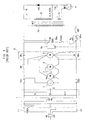
- FIG. 2 is a circuit diagram of a microwave oven according to the present invention. Since the constitution of basic parts of the circuit has already been described with reference to the prior art of Figure 1, a detailed description will not be provided here.
- the preferred embodiment of the present invention is characterized in that a Positive Temperature Coefficient (PTC) thermistor is connected in parallel to the relay switch SW IR .
- PTC Positive Temperature Coefficient
- a PTC thermistor has a resistance that increases suddenly as its internal temperature increases due to a phase transition when its internal temperature reaches a certain temperature.
- the PTC thermistor is a kind of n-type oxide semiconductor that obtains conductivity by adding a very small amount of rare earth elements to BaTiO 3 .
- Curie temperature of the n-type oxide semiconductor can be shifted by substituting Sr or Pb for a portion of Ba.
- the relay 6 When power is applied to the relay coil 6a while the monitor switch SW MT is turned on, the relay 6 turns the relay switch SW IR on after a certain time elapses. Accordingly, the relay switch SW IR is turned on after a surge current is attenuated by the PTC thermistor, so the damage of driving circuits due to the surge current can be prevented, the surge current having high counter-electromotive force that is generated by the high voltage transformer HVT immediately after startup power is applied.
- the relay switch SW IR maintains an off-state even when the power is applied to the relay coil 6a in the state that the monitor switch SW MT turned on, the alternating power is applied to the high voltage transformer HVT via the PTC thermistor.
- the PTC thermistor Since the PTC thermistor is characterized in that its resistance increases with the increase of its internal temperature, it is cut off automatically when the internal temperature reaches a preset temperature (about 100 °C). According to such a characteristic, the PTC thermistor is cut off within a very short time, for example, about one second, under the abnormal conditions. In other words, no adverse effect is given to the electrical parts mounted on the printed circuit board or any signal line even under the abnormal conditions.
- the present invention provides a microwave oven which uses a PTC thermistor connected to a relay switch for attenuating a surge current before the operation of the relay switch in the microwave oven in which users set cooking time and output.
- the PTC thermistor is characterized in that its resistance increases with the increase of its internal temperature, it is cut off within a short time (about one second) when the internal temperature reaches a preset temperature even when it maintains an off-state due to defects of the relay switch, so that an insulation breakdown or an outbreak of fire due to the defects of electrical appliances can be prevented, resulting in improvement of product reliability.
Landscapes
- Physics & Mathematics (AREA)
- Electromagnetism (AREA)
- Control Of High-Frequency Heating Circuits (AREA)
- Emergency Protection Circuit Devices (AREA)
Abstract
Description
Claims (7)
- A microwave oven comprising:characterized in that:an alternating power source;a power supply means for supplying the alternating power to a heating means (MGT); anda current limiting means (PTC) for attenuating a surge current produced when the alternating power is applied through the power supply means;the current limiting means has a resistance that increases in proportion to internal temperature of the current limiting means.
- The microwave oven of claim 1, comprising:wherein the power supply means supplies power during the cooking time set by the cooking timer (8).a cooking timer (8) for setting a cooking time;
- The microwave oven of claim 2, wherein the power supply means comprises a relay for supplying the alternating power to a primary coil (7a) of a high voltage transformer, the relay comprising a relay coil (6a) and a relay switch (SWIR) responding to operation of the cooking timer (8).
- The microwave oven according to claim 3, wherein the current limiting means is connected in parallel to the relay switch (SWIR) .
- The microwave oven according to claim 4, wherein the current limiting means (PTC) is configured to attenuate the surge current until the relay coil (6a) starts to operate the relay switch (SWIR) in order to provide the alternating power.
- The microwave oven according to claim 2 or any claim dependent thereon, wherein the current limiting means (PTC) is connected in series to a power line electrically connecting the cooking timer (8) to a high voltage transformer (HVT), and the power line is arranged in the vicinity of a printed circuit board for supporting electrical parts and a signal line for connecting the electrical parts to the printed circuit board.
- The microwave oven according to any preceding claim, wherein the current limiting means is a PTC thermistor which is cut off when the internal temperature is higher than a preset temperature.
Applications Claiming Priority (2)
| Application Number | Priority Date | Filing Date | Title |
|---|---|---|---|
| KR2002030762 | 2002-05-31 | ||
| KR1020020030762A KR20030092915A (en) | 2002-05-31 | 2002-05-31 | Microwave oven |
Publications (2)
| Publication Number | Publication Date |
|---|---|
| EP1367860A2 true EP1367860A2 (en) | 2003-12-03 |
| EP1367860A3 EP1367860A3 (en) | 2005-07-06 |
Family
ID=29417462
Family Applications (1)
| Application Number | Title | Priority Date | Filing Date |
|---|---|---|---|
| EP02254898A Withdrawn EP1367860A3 (en) | 2002-05-31 | 2002-07-11 | Microwave oven with fire prevention |
Country Status (3)
| Country | Link |
|---|---|
| EP (1) | EP1367860A3 (en) |
| KR (1) | KR20030092915A (en) |
| CN (1) | CN1463171A (en) |
Families Citing this family (5)
| Publication number | Priority date | Publication date | Assignee | Title |
|---|---|---|---|---|
| KR20050076210A (en) * | 2004-01-20 | 2005-07-26 | 삼성전자주식회사 | Microwave oven |
| CN102607077B (en) * | 2012-03-29 | 2014-07-30 | 合肥荣事达三洋电器股份有限公司 | Microwave oven start control method |
| JP6459113B2 (en) * | 2014-07-18 | 2019-01-30 | パナソニックIpマネジメント株式会社 | Switch device and load control system using the same |
| CN105591373B (en) * | 2014-10-23 | 2019-04-09 | 中国石油天然气股份有限公司 | The protection circuit of the controller |
| CN111092545B (en) * | 2019-12-24 | 2020-11-17 | 广东美的白色家电技术创新中心有限公司 | Impulse current suppression device |
Family Cites Families (5)
| Publication number | Priority date | Publication date | Assignee | Title |
|---|---|---|---|---|
| KR970032287A (en) * | 1995-11-10 | 1997-06-26 | 배순훈 | Inrush Current Control Device and Method of Microwave Oven |
| KR19980085394A (en) * | 1997-05-29 | 1998-12-05 | 배순훈 | Inrush current prevention and fire protection device of mechanical microwave oven |
| KR19990002105A (en) * | 1997-06-19 | 1999-01-15 | 배순훈 | Inrush Current Prevention Circuit of Mechanical Microwave |
| US6218652B1 (en) * | 1999-05-29 | 2001-04-17 | Samsung Electronics Co., Ltd. | Apparatus for eliminating inrush current of a microwave oven |
| KR20000075154A (en) * | 1999-05-29 | 2000-12-15 | 윤종용 | Timmer apparatus for a preventing inrush current of a microwave oven |
-
2002
- 2002-05-31 KR KR1020020030762A patent/KR20030092915A/en not_active Ceased
- 2002-07-11 EP EP02254898A patent/EP1367860A3/en not_active Withdrawn
- 2002-07-23 CN CN02126544A patent/CN1463171A/en active Pending
Also Published As
| Publication number | Publication date |
|---|---|
| KR20030092915A (en) | 2003-12-06 |
| CN1463171A (en) | 2003-12-24 |
| EP1367860A3 (en) | 2005-07-06 |
Similar Documents
| Publication | Publication Date | Title |
|---|---|---|
| JPH1118288A (en) | Rush current preventive circuit and power supply for microwave oven | |
| US6218652B1 (en) | Apparatus for eliminating inrush current of a microwave oven | |
| EP1367860A2 (en) | Microwave oven with fire prevention | |
| EP1377128A2 (en) | Microwave oven and method of controlling the same | |
| KR100681578B1 (en) | Microwave fan motor control circuit | |
| KR20000013141A (en) | Microwave oven control method to prevent misoperation | |
| EP1289340B1 (en) | Apparatus and method for controlling output power of combination hood and microwave oven | |
| US20030226841A1 (en) | Safety apparatus for output level-adjustable microwave oven | |
| KR100270873B1 (en) | Inrush current removing apparatus of microwave oven | |
| KR100650781B1 (en) | Microwave wiring structure | |
| KR20000075154A (en) | Timmer apparatus for a preventing inrush current of a microwave oven | |
| KR100268275B1 (en) | Safty circuit for microwave oven | |
| KR200244098Y1 (en) | High Voltage Protection Circuit of Microwave | |
| KR100278004B1 (en) | Safety circuit control method of microwave oven | |
| KR100601430B1 (en) | Error handling method of microwave oven | |
| KR20000075153A (en) | Relay apparatus for a preventing inrush current of a microwave oven | |
| KR200197381Y1 (en) | Safty circuit for microwave oven | |
| KR20000074888A (en) | Over heating protection circuit of a microwave oven | |
| KR20000074889A (en) | Over heating protection circuit of a microwave oven | |
| KR19990001376U (en) | Microwave temperature fuse wiring structure | |
| KR100212258B1 (en) | Inrush Current Prevention Circuit of Mechanical Microwave | |
| KR19980085394A (en) | Inrush current prevention and fire protection device of mechanical microwave oven | |
| KR19980018845U (en) | Microwave power cut off circuit | |
| JP2001351772A (en) | Cooking device | |
| KR19980085393A (en) | Inrush current prevention and fire protection device of electronic microwave oven |
Legal Events
| Date | Code | Title | Description |
|---|---|---|---|
| PUAI | Public reference made under article 153(3) epc to a published international application that has entered the european phase |
Free format text: ORIGINAL CODE: 0009012 |
|
| 17P | Request for examination filed |
Effective date: 20020724 |
|
| AK | Designated contracting states |
Kind code of ref document: A2 Designated state(s): AT BE BG CH CY CZ DE DK EE ES FI FR GB GR IE IT LI LU MC NL PT SE SK TR |
|
| AX | Request for extension of the european patent |
Extension state: AL LT LV MK RO SI |
|
| PUAL | Search report despatched |
Free format text: ORIGINAL CODE: 0009013 |
|
| AK | Designated contracting states |
Kind code of ref document: A3 Designated state(s): AT BE BG CH CY CZ DE DK EE ES FI FR GB GR IE IT LI LU MC NL PT SE SK TR |
|
| AX | Request for extension of the european patent |
Extension state: AL LT LV MK RO SI |
|
| AKX | Designation fees paid |
Designated state(s): DE FR GB |
|
| STAA | Information on the status of an ep patent application or granted ep patent |
Free format text: STATUS: THE APPLICATION IS DEEMED TO BE WITHDRAWN |
|
| 18D | Application deemed to be withdrawn |
Effective date: 20060527 |