EP1367746A1 - Compression of audio signals in a FM transmitter - Google Patents
Compression of audio signals in a FM transmitter Download PDFInfo
- Publication number
- EP1367746A1 EP1367746A1 EP02011220A EP02011220A EP1367746A1 EP 1367746 A1 EP1367746 A1 EP 1367746A1 EP 02011220 A EP02011220 A EP 02011220A EP 02011220 A EP02011220 A EP 02011220A EP 1367746 A1 EP1367746 A1 EP 1367746A1
- Authority
- EP
- European Patent Office
- Prior art keywords
- signal
- multiplex signal
- compressed
- multiplex
- uncompressed
- Prior art date
- Legal status (The legal status is an assumption and is not a legal conclusion. Google has not performed a legal analysis and makes no representation as to the accuracy of the status listed.)
- Withdrawn
Links
- 230000006835 compression Effects 0.000 title claims abstract description 58
- 238000007906 compression Methods 0.000 title claims abstract description 58
- 230000005236 sound signal Effects 0.000 title claims abstract description 51
- 238000000034 method Methods 0.000 claims abstract description 27
- 239000000203 mixture Substances 0.000 claims abstract description 25
- 238000002156 mixing Methods 0.000 claims description 14
- 238000001514 detection method Methods 0.000 claims description 11
- 230000007704 transition Effects 0.000 claims description 9
- 238000004590 computer program Methods 0.000 claims description 7
- 230000007274 generation of a signal involved in cell-cell signaling Effects 0.000 claims description 7
- 230000009467 reduction Effects 0.000 abstract description 36
- 230000001052 transient effect Effects 0.000 description 10
- 230000003595 spectral effect Effects 0.000 description 7
- 238000010586 diagram Methods 0.000 description 5
- 230000005540 biological transmission Effects 0.000 description 3
- 230000003111 delayed effect Effects 0.000 description 3
- 230000008859 change Effects 0.000 description 2
- 238000001914 filtration Methods 0.000 description 2
- 239000011159 matrix material Substances 0.000 description 2
- 238000004364 calculation method Methods 0.000 description 1
- 230000002860 competitive effect Effects 0.000 description 1
- 230000007423 decrease Effects 0.000 description 1
- 230000003247 decreasing effect Effects 0.000 description 1
- 230000001419 dependent effect Effects 0.000 description 1
- 230000004044 response Effects 0.000 description 1
Images




Classifications
-
- H—ELECTRICITY
- H04—ELECTRIC COMMUNICATION TECHNIQUE
- H04H—BROADCAST COMMUNICATION
- H04H20/00—Arrangements for broadcast or for distribution combined with broadcast
- H04H20/44—Arrangements characterised by circuits or components specially adapted for broadcast
- H04H20/46—Arrangements characterised by circuits or components specially adapted for broadcast specially adapted for broadcast systems covered by groups H04H20/53-H04H20/95
- H04H20/47—Arrangements characterised by circuits or components specially adapted for broadcast specially adapted for broadcast systems covered by groups H04H20/53-H04H20/95 specially adapted for stereophonic broadcast systems
- H04H20/48—Arrangements characterised by circuits or components specially adapted for broadcast specially adapted for broadcast systems covered by groups H04H20/53-H04H20/95 specially adapted for stereophonic broadcast systems for FM stereophonic broadcast systems
-
- H—ELECTRICITY
- H04—ELECTRIC COMMUNICATION TECHNIQUE
- H04H—BROADCAST COMMUNICATION
- H04H20/00—Arrangements for broadcast or for distribution combined with broadcast
- H04H20/86—Arrangements characterised by the broadcast information itself
- H04H20/88—Stereophonic broadcast systems
Definitions
- the present invention is related to a signal compression unit for compressing audio signals, and to a FM transmitter comprising a signal compression unit. Furthermore, the invention is related to a method for compressing audio signals.
- Companders are generally known.
- a compander compresses the difference signal before the channel or storage medium and expands after the channel or storage medium. Therewith, audible noise distortions which are added to the transmitted or stored signal are reduced by such a compander.
- One of the best known companders for tape recording purposes is the Dolby-B-type noise reduction system.
- Such a syllable compander calculates the slowly varying envelope amplitude of the audio signal and compresses/ expands the audio signal according thereto.
- a detailed description of companders and in particular of the Dolby NR (Noise Reduction) system can be found under http://www.dolby.com/ken.
- DE 41 28 045 A1 describes to add the compressed difference signal to the lower sideband of the modulated 38 kHz carrier and to subtract the compressed difference signal from the upper sideband of the modulated 38 kHz carrier before transmission of the so modified multiplex signal.
- a mathematical analysis of both described modulation systems leads to the finding that the better and therefore preferred solution is the method described in DE 41 28 045 A1.
- the FM multiplex signal includes a sum signal, a difference signal, and additionally, a compressed difference signal.
- the compressor for compressing the difference signal comprises a first delay element arranged in the signal path of the difference signal to introduce a group delay linked to the generation of the compressor gain, and a second delay element arranged in the signal path of the sum signal to introduce a group delay linked to the generation of the compressor gain. Furthermore, it is disclosed to use both the sum signal and the difference signal for determining the compressor gain.
- the audio signal amplitude is reduced.
- This method has the disadvantage that the reduction of the audio amplitude is related to a reduction of the audio SNR (signal to noise ratio) since the audio signal power is reduced.
- many broadcasters try to transmit their audio signal as loud as possible in order to achieve a "competitive" audio signal.
- the peak amplitude is limited by means of a limiter.
- This method has the disadvantage that the increased peak amplitude of the advanced multiplex signal leads to an increased amount of limitations of the multiplex signal in the transmitter. Thus, the audio signal in an advanced FM receiver and a conventional FM receiver is disturbed.
- a reduction of the peak amplitude is achieved by using preemphase filters with variable time constant, or by using audio filters with time-variant transfer functions.
- the object of the invention is solved by a signal compression unit for compressing audio signals according to claim 1, by a FM transmitter according to claim 10, and by a method for compressing audio signals according to claim 12. Preferred embodiments thereof are respectively defined in the following dependent sub-claims.
- a computer program product according to the present invention is defined in claim 19 and a computer readable storage medium according to the present invention is defined in claim 20.
- the signal compression unit for compressing audio signals in a FM transmitter comprises first multiplex signal generation means for generating an uncompressed multiplex signal from said audio signals, and second multiplex signal generation means for generating a compressed multiplex signal from said audio signals. Furthermore, the signal compression unit comprises an overmodulation detection unit for detecting overmodulation of said compressed multiplex signal, and a blending unit for blending said compressed multiplex signal and said uncompressed multiplex signal in order to generate a blended output signal. Whenever overmodulation of said compressed multiplex signal is detected, the contribution of said uncompressed multiplex signal to said blended output signal is increased.
- An increasing of the contribution of said uncompressed multiplex signal can be described by a uniformly reduction of the compression gains of all the subbands of the compressed multiplex signal.
- a peak reduction of the blended output signal is obtained, and overmodulation due to transient overshoots is avoided.
- the blending ratio can be continuously varied, and therefore, any required degree of peak reduction can be obtained.
- a peak reduction is achieved by reducing the compression.
- the contribution of the uncompressed multiplex signal decreases the compression gain for the low power components.
- the contribution of these low power components to the audio signal is reduced. Since the power of these signal components is low compared to the audio signal power, a reduction of the compression of these signal components is not audible.
- the reception of a state of the art FM receiver is not disturbed at all by the peak reduction method according to the invention.
- said overmodulation detection unit comprises a comparator for comparing the amplitude of said compressed multiplex signal with a predefined threshold level, whereby overmodulation is detected whenever said amplitude exceeds said predefined threshold level. Even short transient overshoots can be detected by means of a comparator. By employing time delay units, a look-ahead detection of transient overshoots can be implemented.
- the respective contributions of said compressed multiplex signal and of said uncompressed multiplex signal to said blended output signal are varied in a sliding transition.
- sliding transitions are preferred.
- the respective contributions of said compressed multiplex signal and of said uncompressed multiplex signal to said blended output signal are controlled by a blend control signal that is generated by said overmodulation detection unit.
- the blend control signal assumes a value of 1
- the blended output signal is identical to the compressed multiplex signal, and the uncompressed multiplex signal does not contribute.
- the blend control signal assumes the value 0
- the blended output signal is identical to the uncompressed multiplex signal, and the compressed signal does not contribute to the blended output signal.
- the amplitude of said blend control signal is smoothly varied according to a Gauss-shaped pulse.
- a sliding transition having a Gauss shape is recommended for the reduction of the peak amplitude of an OFDM signal.
- said blended output signal is set to said compressed multiplex signal in case no overmodulation is detected.
- a maximum compression can be obtained, and the noise reduction is at its maximum.
- the respective contributions of said compressed multiplex signal and of said uncompressed multiplex signal to said blended output signal are chosen such that the contribution of said uncompressed multiplex signal to said blended output signal is the minimum contribution sufficient for avoiding overmodulation.
- said second multiplex signal generation means for generating said compressed multiplex signal comprise a multiband compressor which generates said compressed multiplex signal on basis of subbands thereof.
- the respective compressor gain is individually set with regard to the amplitude of the spectral components within said subband.
- a sum signal and a difference signal are transmitted.
- the right channel audio signal and the left channel audio signal are converted into a sum signal and a difference signal, and these two signals are transmitted.
- the difference signal is modulated to the lower sideband of the suppressed 38 kHz carrier of the uncompressed multiplex signal.
- a sum signal, an uncompressed difference signal and a compressed difference signal are transmitted. Both the compressed and the uncompressed difference signal are transmitted within the compressed multiplex signal. Because of its rather large signal to noise ratio, the sum signal is not compressed at all.
- the FM transmitter according to the invention comprises a signal compression unit as described above.
- the inventive method for compressing audio signals is characterized by the following steps: First, an uncompressed multiplex signal and a compressed multiplex signal are generated from said audio signals. Said compressed multiplex signal and said uncompressed multiplex signal are blended in order to generate a blended output signal. Overmodulation of said compressed multiplex signal is detected, and in case of overmodulation, the contribution of said uncompressed multiplex signal to said blended output signal is increased.
- the invention does not have to be implemented in hardware.
- the invention can also be realised as a computer program product which carries out the method steps as described above when said computer program product is executed on a computer, digital signal processor or the like.
- a block diagram of a state of the art FM transmitter is depicted.
- the stereo audio signal 1 is input to an audio/modulation processor 2.
- the audio/modulation processor 2 performs an equalizing of the audio signal, a preemphase filtering of the audio signal, and a compression of the audio signal in order to increase the audio signal power. This compression is not related to noise reduction, though.
- a multiplex signal 3 is generated, and a peak reduction of said multiplex signal 3 is performed.
- the multiplex signal 3 is forwarded to a FM modulator 4, which outputs the transmission signal 5.
- Fig. 2 shows a block diagram of a FM transmitter according to the invention.
- a stereo audio signal 6 is input to an audio/modulation processor 7.
- the audio/modulation processor performs an equalizing, a preemphase filtering, an audio compression for the purpose of increasing the audio signal power, and an audio manipulation for avoiding the FM overmodulation.
- the audio/modulation processor 7 outputs a pre-processed stereo audio signal 8, which is forwarded to a multiplex signal generation and peak reduction unit.
- the pre-processed stereo audio signal 8 is input to a multiplexer with compression 9. At the output of the multiplexer with compression 9, a compressed multiplex signal 10 is obtained.
- the pre-processed stereo audio signal 8 is also input to a multiplexer without compression 11.
- the compressor gain is fixed to 1, and therefore, the "compressed" difference signal is identical to the difference signal itself.
- the uncompressed multiplex signal 12 is obtained.
- the compressor gain is set to a value greater than 1. This leads to an increase of the peak amplitude of the compressed multiplex signal 10.
- the overmodulation detection unit 13 detects signal components in the compressed multiplex signal 10 with a signal amplitude that leads to an overmodulation of the FM modulator 14. In case an overmodulation is detected, the overmodulation detection unit 13 outputs a blend control signal 15 that is forwarded to the blending unit 16. Both the uncompressed multiplex signal 12 and the compressed multiplex signal 10 are forwarded as input signals to the blending unit 16.
- the value of the blend control signal 15 determines the respective contributions of the uncompressed multiplex signal 12 and of the compressed multiplex signal 10 to the blended output signal 17. In case the amplitude of the blend control signal 15 is 1, the blended output signal 17 is equal to the compressed multiplex signal 10. In case the amplitude of the blend control signal 15 is 0, the blended output signal 17 is equal to the uncompressed multiplex signal 12.
- the overmodulation detection unit 13 In case an overmodulation is detected by the overmodulation detection unit 13, the contribution of the uncompressed multiplex signal 10 to the blended output signal 17 is increased, and the contribution of the compressed (and powerful) multiplex signal 12 to the blended output signal 17 is decreased, at least for a short period of time. By doing this, the peak amplitude of the blended output signal 17 is reduced, and overmodulation is avoided. In most cases, a slight change of the respective contributions is sufficient in order to avoid overmodulation.
- the blended output signal 17 is forwarded to the FM modulator 14, which generates the FM transmission signal 18.
- This blending to the advanced multiplex signal without compression is identical to a reduction of the compression gains of all subbands of the difference signal.
- the compression gains of all subbands are uniformly reduced.
- the spectral components that dominate the audio signal are not influenced by this peak amplitude reduction method, since subbands with a high signal power are not compressed at all (their compression gain is equal to one), and so a blending does not change the signal content of such an uncompressed subband.
- Signal components with a very low signal power are compressed in the FM transmitter in order to achieve a noise reduction on part of the receiver.
- These signal components lead to the increase of the amplitude of the compressed multiplex signal 10 compared to the uncompressed multiplex signal 12. These signal components have a very low signal power compared to the audio signal power. Their contribution to the audio signal of an FM receiver is reduced by a reduction of the compression caused by a blending according to this invention. The reception of a state of the art FM receiver (conventional FM receiver) is not disturbed at all by the blending operation. Since these signal components are low compared to the audio signal power, a reduction of the compression of these signal components is not audible in receivers comprising an expander to perform a noise reduction.
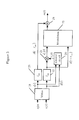
- a principle block diagram of the multiplexer with a broadband compression 9 is given.
- the audio signal for the left channel a 1 (t) and the audio signal for the right channel a r (t) are input to a matrix circuit 19 which outputs the sum signal s(t) and the difference signal d(t).
- the sum signal s(t) and the difference signal d(t) are input to a control circuit 20 which determines a compressor gain c c (t) with which the difference signal gets compressed by means of a multiplier 21.
- the control circuit 20 and the multiplier 21 together build the compressor.
- the control circuit 20 has a certain group delay T for the calculation of the compressor gain c c (t).
- an attack time should be considered in which the gain is slowly varied from a current level to a wanted level. Therefore, to avoid transient overshoots the delayed difference signal d(t-T) gets compressed.
- a first delay element 22 with delay T is arranged in the signal path of the difference signal d(t) preceding said multiplier 21 of the compressor.
- the control circuit 20 receives the undelayed difference signal d(t).
- the delayed difference signal d(t-T) and the corresponding compressed difference signal d c (t) are input to a modulation circuit 23 which modulates both signal as it is described in DE 41 28 045 A1, for example.
- the output signal of the modulator 23 is input to an adder 24 which adds thereto the correspondingly delayed sum signal s(t-T) which is output by a second delay element 25 receiving the sum signal s(t) from the matrix circuit 19.
- the adder 24 outputs the multiplex signal m(t).
- a multi-band compressor is used instead of the above described broadband compressor.
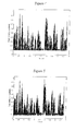
- Fig. 4 the peak amplitudes of the multiplex signals of different multiplexers for the same audio signal are depicted.
- the peak multiplex signal amplitude of a conventional multiplex signal (without compression and with double sideband modulated difference signal) is shown, whereby a peak multiplex amplitude of 1 corresponds to a frequency deviation of 75 kHz in the modulated FM signal.
- the amplitude of the peak multiplex signal does not exceed the value 1.
- Fig. 5 the peak multiplex amplitude of an advanced multiplex signal without compression is depicted, whereby a peak multiplex amplitude of 1 corresponds to a frequency deviation of 75 kHz in the modulated FM signal. Also here, the peak multiplex amplitude does not exceed the value 1.
- Fig. 6 depicts the peak multiplex signal amplitude of an advanced multiplex signal with compression. Again, a peak multiplex amplitude of 1 corresponds to a frequency deviation of 75 kHz. Due to the signal compression, the peak multiplex amplitude surmounts the value 1 from time to time, for example at t ⁇ 0.8 sec and at t ⁇ 3 sec. At these points of time, an overmodulation of the modulated FM signal will occur.
- Fig. 7 the peak multiplex signal amplitude of an advanced multiplex signal with compression is shown again for the same audio signal as in Fig. 6, but now a reduction of the peak amplitude according to the invention is performed. For this reason, the peak multiplex amplitude does no longer surmount the value 1. Especially at t ⁇ 0.8 sec and at t ⁇ 3 sec, where transient overshoots have occurred in Fig. 6, the peak multiplex signal amplitude stays below 1.
- the amplitude of the blend control signal is shown as a function of time for the example given in Fig. 7.
- the blend control signal controls the blending unit and determines the contribution of the uncompressed multiplex signal and the contribution of the compressed multiplex signal to the blended output signal.
- the amplitude of the blend control signal is 1, the blended output signal is equal to the compressed multiplex signal, and the contribution of the uncompressed multiplex signal is zero. Accordingly, when the amplitude of the blend control signal is set to 0, the blended output signal would be equal to the uncompressed multiplex signal.
- the amplitude of the blend control signal is equal to 1 as long as there are no transient overshoots of the compressed multiplex signal.
- the blended output signal is equal to the compressed multiplex signal.
- a peak reduction of the blended output signal is performed by temporarily increasing the contribution of the uncompressed multiplex signal to the blended output signal. For this reason, the blend control signal is temporarily reduced in a Gauss shaped transition at the points of time t ⁇ 0.5 sec, t ⁇ 0.8 sec and t ⁇ 3 sec, as depicted in Fig. 8.
- transm_mux blend_control ⁇ adv_with_compr + (1 - blend_control) adv_without_compr
- the parameter blend_control denotes the blend control value shown in Fig. 8.
- the parameter adv_with_compr denotes the respective amplitude of the compressed multiplex signal, which might exceed one in case of a peak
- the parameter adv_without_compr denotes the respective amplitude of the uncompressed multiplex signal.
- the parameter transm_mux denotes the desired value of the blended output signal.
- the blend control signal advantageously changes its value in a sliding transition.
- the sliding transition can have a Gauss shape, as shown in Fig. 8.
- a Gauss shape is recommended for the reduction of the peak amplitude of an OFDM signal.
Landscapes
- Engineering & Computer Science (AREA)
- Signal Processing (AREA)
- Reduction Or Emphasis Of Bandwidth Of Signals (AREA)
Abstract
Description
- Fig. 1
- shows a block diagram of a state of the art FM transmitter,
- Fig. 2
- shows a FM transmitter according to the invention,
- Fig. 3
- shows a block diagram of a multiplexer with broadband compression,
- Fig. 4
- shows the peak multiplex signal amplitude of a conventional multiplex signal without compression (in especially, the difference signal is double sideband modulated),
- Fig. 5
- shows the peak multiplex signal amplitude of a multiplex signal without compression (in especially, the difference signal is single sideband modulated to the lower sideband),
- Fig. 6
- shows the peak multiplex signal amplitude of a multiplex signal with compression, whereby transient overshoots can be recognised,
- Fig. 7
- shows the peak multiplex signal amplitude of a blended multiplex signal according to the invention, and
- Fig. 8
- depicts the blend control signal that determines the contribution of the uncompressed multiplex signal and of the compressed multiplex signal to the blended output signal.
Claims (20)
- Signal compression unit for compressing audio signals in a FM transmitter, characterized byfirst multiplex signal generation means (11) for generating an uncompressed multiplex signal (12) from said audio signals (6);second multiplex signal generation means (9) for generating a compressed multiplex signal (10) from said audio signals (6);an overmodulation detection unit (13) for detecting overmodulation of said compressed multiplex signal (10);a blending unit (16) for blending said compressed multiplex signal (10) and said uncompressed multiplex signal (12) in order to generate a blended output signal (17), whereby, whenever overmodulation of said compressed multiplex signal (10) is detected, the contribution of said uncompressed multiplex signal (12) to said blended output signal (17) is increased.
- Signal compression unit according to claim 1, characterized in that said overmodulation detection unit comprises a comparator for comparing the amplitude of said compressed multiplex signal with a predefined threshold level, whereby overmodulation is detected whenever said amplitude exceeds said predefined threshold level.
- Signal compression unit according to claim 1 or claim 2, characterized in that the respective contributions of said compressed multiplex signal and of said uncompressed multiplex signal to said blended output signal are varied in a sliding transition.
- Signal compression unit according to anyone of claims 1 to 3. characterized in that the respective contributions of said compressed multiplex signal and of said uncompressed multiplex signal to said blended output signal are controlled by a blend control signal that is generated by said overmodulation detection unit.
- Signal compression unit according to claim 4, characterized in that whenever overmodulation is detected, the amplitude of said blend control signal is smoothly varied according to a Gauss-shaped pulse.
- Signal compression unit according to anyone of claims 1 to 5, characterized in that in case no overmodulation is detected, said blended output signal is set to said compressed multiplex signal.
- Signal compression unit according to anyone of claims 1 to 6, characterized in that in case of overmodulation, the respective contributions of said compressed multiplex signal and of said uncompressed multiplex signal to said blended output signal are chosen such that the contribution of said uncompressed multiplex signal to said blended output signal is the minimum contribution sufficient for avoiding overmodulation.
- Signal compression unit according to anyone of claims 1 to 7, characterized in that said second multiplex signal generation means for generating said compressed multiplex signal comprise a multiband compressor which generates said compressed multiplex signal on basis of subbands thereof.
- Signal compression unit according to anyone of claims 1 to 8, characterized in that within said uncompressed multiplex signal, a sum signal and a difference signal are transmitted.
- Signal compression unit according to anyone of claims 1 to 9, characterized in that within said compressed multiplex signal, a sum signal, an uncompressed difference signal and a compressed difference signal are transmitted.
- FM transmitter comprising a signal compression unit according to anyone of claims 1 to 10.
- Method for compressing audio signals, characterized by the following steps:generating an uncompressed multiplex signal (12) and a compressed multiplex signal (10) from said audio signals (6);blending said compressed multiplex signal (10) and said uncompressed multiplex signal (12) in order to generate a blended output signal (17);detecting overmodulation of said compressed multiplex signal (10);in case of overmodulation, increasing the contribution of said uncompressed multiplex signal (12) to said blended output signal (17).
- Method according to claim 12, characterized by comparing the amplitude of said compressed multiplex signal with a predefined threshold level, whereby overmodulation is detected whenever said amplitude exceeds said predefined threshold level.
- Method according to claim 12 or 13, characterized by varying the respective contributions of said compressed multiplex signal and of said uncompressed multiplex signal to said blended output signal in a sliding transition.
- Method according to anyone of claims 12 to 14, characterized by controlling the respective contributions of said compressed multiplex signal and of said uncompressed multiplex signal to said blended output signal by a blend control signal that is generated by said overmodulation detection unit.
- Method according to claim 15, characterized by smoothly varying the amplitude of said blend control signal according to a Gauss-shaped pulse.
- Method according to anyone of claims 12 to 16, characterized by setting said blended output signal to said compressed multiplex signal in case no overmodulation is detected.
- Method according to anyone of claims 12 to 17, characterized by choosing, in case of overmodulation, the respective contributions of said compressed multiplex signal and of said uncompressed multiplex signal to said blended output signal such that the contribution of said uncompressed multiplex signal to said blended output signal is the minimum contribution sufficient for avoiding overmodulation.
- Computer program product, comprising computer program means adapted to perform the method steps for compressing audio signals as defined in anyone of claims 12 to 18or to embody the features of the signal compression unit as defined in anyone of claims 1 to 10 when said computer program product is executed on a computer, digital signal processor, or the like.
- Computer readable storage medium storing thereon a computer program product according to claim 19.
Priority Applications (1)
| Application Number | Priority Date | Filing Date | Title |
|---|---|---|---|
| EP02011220A EP1367746A1 (en) | 2002-05-21 | 2002-05-21 | Compression of audio signals in a FM transmitter |
Applications Claiming Priority (1)
| Application Number | Priority Date | Filing Date | Title |
|---|---|---|---|
| EP02011220A EP1367746A1 (en) | 2002-05-21 | 2002-05-21 | Compression of audio signals in a FM transmitter |
Publications (1)
| Publication Number | Publication Date |
|---|---|
| EP1367746A1 true EP1367746A1 (en) | 2003-12-03 |
Family
ID=29414685
Family Applications (1)
| Application Number | Title | Priority Date | Filing Date |
|---|---|---|---|
| EP02011220A Withdrawn EP1367746A1 (en) | 2002-05-21 | 2002-05-21 | Compression of audio signals in a FM transmitter |
Country Status (1)
| Country | Link |
|---|---|
| EP (1) | EP1367746A1 (en) |
Citations (3)
| Publication number | Priority date | Publication date | Assignee | Title |
|---|---|---|---|---|
| US4323731A (en) * | 1978-12-18 | 1982-04-06 | Harris Corporation | Variable-angle, multiple channel amplitude modulation system |
| US4752955A (en) * | 1987-03-25 | 1988-06-21 | Broadcast Technology Partners | FM stereophonic system having improved compatibility in presence of multipath |
| DE4128045A1 (en) * | 1991-08-23 | 1993-02-25 | Telefunken Sendertechnik | Noise suppression for stereo radio - compresses lower and upper side bands of differential signal in stereo transmitter |
-
2002
- 2002-05-21 EP EP02011220A patent/EP1367746A1/en not_active Withdrawn
Patent Citations (3)
| Publication number | Priority date | Publication date | Assignee | Title |
|---|---|---|---|---|
| US4323731A (en) * | 1978-12-18 | 1982-04-06 | Harris Corporation | Variable-angle, multiple channel amplitude modulation system |
| US4752955A (en) * | 1987-03-25 | 1988-06-21 | Broadcast Technology Partners | FM stereophonic system having improved compatibility in presence of multipath |
| DE4128045A1 (en) * | 1991-08-23 | 1993-02-25 | Telefunken Sendertechnik | Noise suppression for stereo radio - compresses lower and upper side bands of differential signal in stereo transmitter |
Similar Documents
| Publication | Publication Date | Title |
|---|---|---|
| EP0298959B1 (en) | Fm receiver with noise suppression during rayleigh faded received signals | |
| EP0685130B1 (en) | Digital audio limiter | |
| US7715567B2 (en) | Noise reduction in a stereo receiver | |
| US6154547A (en) | Adaptive noise reduction filter with continuously variable sliding bandwidth | |
| US4661851A (en) | Apparatus for reducing the effect of noise interference in audio companding system | |
| US4752955A (en) | FM stereophonic system having improved compatibility in presence of multipath | |
| US7292694B2 (en) | Noise reduction in a stereo receiver | |
| CN102903363B (en) | Stereo decoding | |
| CN107210768A (en) | Carrier-to-noise ratio detects circuit and receiving circuit | |
| US7313240B2 (en) | Noise reduction in a stereo receiver comprising an expander | |
| EP1289157A1 (en) | Linear phase compander for FM broadcast | |
| JPH0629878A (en) | Radio receiver | |
| US7362872B2 (en) | Method for noise reduction of a FM signal | |
| US10090818B1 (en) | Adaptive signal compressor for AM radio | |
| US4679239A (en) | Apparatus and method for processing stereo signals for application to an AM stereo broadcasting unit | |
| SU1195460A1 (en) | Device for reception of stereophonic signals | |
| JP3276684B2 (en) | Multipath noise removal circuit for FM receiver | |
| EP2602933B1 (en) | Analog signal transfer system, variable compressor and variable expander | |
| Murali et al. | Overmodulation protection in FM transmitters | |
| JP2845201B2 (en) | Diversity receiver with combining method | |
| EP1361663B1 (en) | Noise detection in FM broadcast | |
| JPH08316925A (en) | Multipath noise reduction device | |
| JP2012225982A (en) | Speech processing device | |
| JPS6234305B2 (en) | ||
| JPH0530054A (en) | Fm stereo receiver |
Legal Events
| Date | Code | Title | Description |
|---|---|---|---|
| PUAI | Public reference made under article 153(3) epc to a published international application that has entered the european phase |
Free format text: ORIGINAL CODE: 0009012 |
|
| 17P | Request for examination filed |
Effective date: 20030415 |
|
| AK | Designated contracting states |
Kind code of ref document: A1 Designated state(s): AT BE CH CY DE DK ES FI FR GB GR IE IT LI LU MC NL PT SE TR |
|
| AX | Request for extension of the european patent |
Extension state: AL LT LV MK RO SI |
|
| AKX | Designation fees paid |
Designated state(s): DE FR GB |
|
| RAP1 | Party data changed (applicant data changed or rights of an application transferred) |
Owner name: SONY DEUTSCHLAND GMBH |
|
| RAP1 | Party data changed (applicant data changed or rights of an application transferred) |
Owner name: SONY DEUTSCHLAND GMBH |
|
| 17Q | First examination report despatched |
Effective date: 20090217 |
|
| STAA | Information on the status of an ep patent application or granted ep patent |
Free format text: STATUS: THE APPLICATION IS DEEMED TO BE WITHDRAWN |
|
| 18D | Application deemed to be withdrawn |
Effective date: 20090630 |