EP1367738A1 - Distributed echo cancelling - Google Patents
Distributed echo cancelling Download PDFInfo
- Publication number
- EP1367738A1 EP1367738A1 EP03253161A EP03253161A EP1367738A1 EP 1367738 A1 EP1367738 A1 EP 1367738A1 EP 03253161 A EP03253161 A EP 03253161A EP 03253161 A EP03253161 A EP 03253161A EP 1367738 A1 EP1367738 A1 EP 1367738A1
- Authority
- EP
- European Patent Office
- Prior art keywords
- echo
- signal
- network
- reference signal
- cancelling
- Prior art date
- Legal status (The legal status is an assumption and is not a legal conclusion. Google has not performed a legal analysis and makes no representation as to the accuracy of the status listed.)
- Granted
Links
- 238000002592 echocardiography Methods 0.000 claims abstract description 19
- 230000000694 effects Effects 0.000 claims description 6
- 230000005540 biological transmission Effects 0.000 claims description 5
- 238000000034 method Methods 0.000 claims description 3
- 230000006870 function Effects 0.000 abstract description 7
- 238000010586 diagram Methods 0.000 description 22
- 230000001360 synchronised effect Effects 0.000 description 7
- 230000006835 compression Effects 0.000 description 5
- 238000007906 compression Methods 0.000 description 5
- 238000004891 communication Methods 0.000 description 3
- 230000001934 delay Effects 0.000 description 3
- 230000006978 adaptation Effects 0.000 description 2
- 230000003044 adaptive effect Effects 0.000 description 2
- 230000003111 delayed effect Effects 0.000 description 2
- 238000010348 incorporation Methods 0.000 description 2
- 230000000977 initiatory effect Effects 0.000 description 2
- 238000003780 insertion Methods 0.000 description 2
- 230000037431 insertion Effects 0.000 description 2
- 230000008878 coupling Effects 0.000 description 1
- 238000010168 coupling process Methods 0.000 description 1
- 238000005859 coupling reaction Methods 0.000 description 1
- 230000006837 decompression Effects 0.000 description 1
- 230000001419 dependent effect Effects 0.000 description 1
- 238000002347 injection Methods 0.000 description 1
- 239000007924 injection Substances 0.000 description 1
- 230000009022 nonlinear effect Effects 0.000 description 1
- 238000005070 sampling Methods 0.000 description 1
- 239000006163 transport media Substances 0.000 description 1
Images



Classifications
-
- H—ELECTRICITY
- H04—ELECTRIC COMMUNICATION TECHNIQUE
- H04B—TRANSMISSION
- H04B3/00—Line transmission systems
- H04B3/02—Details
- H04B3/20—Reducing echo effects or singing; Opening or closing transmitting path; Conditioning for transmission in one direction or the other
- H04B3/23—Reducing echo effects or singing; Opening or closing transmitting path; Conditioning for transmission in one direction or the other using a replica of transmitted signal in the time domain, e.g. echo cancellers
-
- H—ELECTRICITY
- H04—ELECTRIC COMMUNICATION TECHNIQUE
- H04M—TELEPHONIC COMMUNICATION
- H04M9/00—Arrangements for interconnection not involving centralised switching
- H04M9/08—Two-way loud-speaking telephone systems with means for conditioning the signal, e.g. for suppressing echoes for one or both directions of traffic
- H04M9/082—Two-way loud-speaking telephone systems with means for conditioning the signal, e.g. for suppressing echoes for one or both directions of traffic using echo cancellers
Definitions
- This invention relates to echo cancelling and in particular to distributed echo cancelling.
- echo cancelling The purpose of echo cancelling is to compensate a signal for echoes caused by various sources including feedback from a speaker in close proximity to a microphone.
- prior art echo cancellers use a reference signal to determine the echoes and accordingly compensate the signal by removing (subtracting) an estimate of the echoes from the signal.
- echo cancelling either acoustic or line
- the delays in the network are compensated by increasing buffer size and thus memory requirements.
- Unreliable transport media such as Internet Protocol networks, have an additional problem of packet loss, which can considerably reduce the effectiveness of an echo canceller.
- the conventional echo canceller 100 comprises an echo estimator and control 110 and a subtractor 120.
- An input signal (Sin 130) is a combination of an Echo 132 (the echoes) and the near end signal.
- the echo estimator and control 110 uses the reference signal (Rout or Rin) 134 and the subtractor 120 to remove an estimate of the echo from the input signal 130.
- the goal of the echo canceller is to create an output signal (Sout 136) that matches the near end signal as closely as possible with the echo sufficiently reduced.
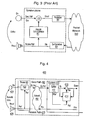
- FIG. 2 there is shown a block diagram of a conventional full duplex hands free (FDHF) echo canceller 200 for a traditional speakerphone.
- the FDHF echo canceller 200 includes a line echo estimator and control 210 as well as a first subtractor 215 for cancelling line echo 217 (the echoes) introduced by a network (not shown).
- An acoustic echo estimator is provided along with control 220 and a second subtractor 222 for cancelling acoustic echo 224 between loudspeaker 226 and microphone 228.
- FIG. 3 there is shown a block diagram of a conventional packet network based acoustic echo canceller 300 for connection with a packet network 350.
- line echo is typically cancelled at IP/PSTN gateways (not shown).
- the canceller 300 comprises an acoustic echo estimator 300, a subtractor 310, a packetizer 320 and de-packetizer 330.
- these echo-cancelling resources are located on the phone, which increases the cost for each of the phone sets.
- These echo-cancelling resources are usually idle, since for most of the time, users are not using the speakerphone feature.
- a distributed echo cancelling architecture is provided where echo-canceling functions are performed at locations remote from devices receiving signals with echoes.
- the echo cancelling functions use the input (transmit) signal, which has been corrupted with the echoes at the devices, along with a copy of the reference signal as received at the devices, for echo cancellation.
- echo canceller resources are located at a central system and not at each individual device, the echo canceller resources can be shared between the devices.
- a communication system comprising a system having an echo cancelling function for cancelling echoes from at least one signal using a first reference signal; and at least one device that is remote from the system over a network for receiving a second reference signal comprising the first reference signal as modified by network effects due to transmission over the network, for initiating incorporation of the echoes into the second reference signal to form a part of respective one of said at least one signal, and for receiving and transmitting said at least one signal to the system over the network.
- a method of distributed echo cancelling in a communication system comprising transmitting a first reference signal to at least one device that is remote over a network; receiving a second reference signal by said at least one device where the second reference signal comprises the first reference signal as modified by network effects due to transmission over the network; initiating incorporation of echoes at said at least one device into the second reference signal to form a part of at least one signal where said at least one signal also has the echoes; receiving said at least one signal over the network; and cancelling the echoes from said at least one signal using the first reference signal.
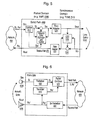
- the distributed acoustic echo canceller 400 comprises a system 410 with a splitter 412, an acoustic echo estimator and control 414 and a subtractor 416; a phone device 420 with a signal combiner 422, a microphone 424, and a loudspeaker 426.
- the acoustic echo estimator and control 414 will be understood by a person of ordinary skill in the art to be an adaptive filter (see for example "Adaptive Filter Theory", 3 rd edition. Simon Haykin, Prentice Hall, 1996. ISBN 0-13-322-760-X.
- the system 410 sends a first reference signal Ro to the phone device 420.
- the first reference signal Ro is delayed and potentially corrupted by a network 450 (such as packet loss / frame erasure compensation /vocoding / delay jitter) when it arrives at the phone device 420 as a second reference signal Ro'.
- the second reference signal Ro' is sent to the loudspeaker 426 of the phone device 420. Due to acoustic coupling, a first signal Si (equivalent to Sin), comprising a near end signal (such as a voice signal) and an acoustic echo signal, is picked up at the microphone 424. This first signal Si, in conjunction with the transmitted signal Ro', is sent back to the system 410.
- the splitter 412 splits the combined signal Si, Ro' and the second reference signal Ro' is used as a reference signal in the acoustic echo estimator and control 414, resulting in echo cancelled signal So.
- the splitter 412 further monitors the incoming signal (Si, Ro') for lost packets and other corruption, and controls the acoustic echo estimator and control 414 accordingly.
- the phone device 412 further comprises a compression device (not shown)
- the combined signal is also decompressed in the splitter 412 as the acoustic echo estimator and control 414 operates on uncompressed samples.
- Some speech vocoders such as for example G.729, have their own packet loss compensation / frame erasure schemes. Thus, if there is packet loss in send path 460, any adaptation of the acoustic echo estimator and control 414 is frozen to prevent divergence of the distributed echo canceller 400 in packet loss situations.
- the distributed echo canceller 400 is thus not affected by any network delays as the second reference signal Ro' (and not Ro) is used as the reference signal. Furthermore, non-linear effects in receive path 470 such as packet loss are not relevant as there is an exact copy of the second reference signal Ro', after network effects, that is sent to the loudspeaker 426. Packet loss in the send path 460 (Si + Ro') is determined by the protocol of the network 450. Consequently, this echo cancelling structure is not dependent on network delay and can be made more robust with regard to packet loss / frame erasure.
- FIG. 5 there is shown a block diagram of the distributed acoustic echo canceller 400 of Figure 4 (a Full Duplex Handsfree (FDHF) structure) in a packet domain 500 interfacing to a synchronous domain 510.
- the packet domain 500 includes voice over IP (VoIP) networks.
- the synchronous domain 510 includes time division multiplexed (TDM) networks such as the PSTN.
- the phone device 420 (phone side) is as shown in Figure 4.
- Rate adapters 520, 522 are required to interface the packet domain 500 with the synchronous domain 510.
- the rate adapter 522 in the receive path may also contain a speech compression unit, if speech compression is required.
- a line echo canceller (530 and 535) is used in the synchronous domain 510 to cancel line echo 550.
- a de-packetizer 600 converts packet data into the second reference signal Ro' that is sent to the loudspeaker 426.
- the de-packetizer 600 compensates for network effects such as lost packets / frame erasure and clock drift (sampling rate adjustment). As a result of these network effects, received packets may be corrupted and are consequently indicated by the second reference signal Ro'.
- Packetizer 610 converts the second reference signal Ro' sent to the loudspeaker 426 back into packet data for a packet combiner 620.
- Packetizer 630 packetizes the signal Si received from the microphone 424. Both packets are then combined by the packet combiner 620 and sent over the network 450.
- the packetizers 610, 630 respectively digitize the signal Si and the second reference signal Ro' (synchronous voice streams) into packets.
- voice decompression may be performed by the de-packetizer 600 and voice compression by the packetizers 610, 630.
- voice compression standards are the International Telecommunication Union (ITU) standards G.711, G.729, and G.732.1.
- the telephone system 700 comprises a system 710 having control logic 715 for controlling a pool of Full Duplex Handsfree (FDHF) echo cancellers 720; and a plurality of phone devices 730, 740 connected to the switch 710 over a network 750.
- FDHF Full Duplex Handsfree
- One such phone device 740 is shown in a speakerphone mode.
- the switch 710 is, for example, an IP PBX switch.
- this telephone system 700 by default all of the phone devices 730, 740 are in handset mode where a user uses a handset, and not a loudspeaker, to converse. In the handset mode, no speakerphone resources, such as acoustic echo cancelling, are needed.
- the phone device 740 When the user hits a speakerphone key, the phone device 740 is put into speakerphone mode as shown in Figure 7.
- a combined signal Si, Ro' which comprises a received reference signal Ro' and a microphone signal Si, is sent back to the switch 710 over the network 750.
- a speakerphone resource is allocated out of the pool of FDHF 720 to perform echo cancelling functions on the combined signal Si, Ro'.
- the speakerphone resources of the telephone system 700 are shared among the users.
- the speakerphone echo cancelling resources at the switch may be of a higher quality than echo cancelling resources at each device as the cost is mitigated over more than one user.
- the distributed echo canceller 800 comprises a phone device 802, and a system 804 with a subtractor 808 and an acoustic echo estimator and control (AEC) 806.
- the reliable network 810 is, for example, a TDM connection.
- reference signal Ro' is a delayed version of a reference signal Ro. Thus, it is not necessary to send the reference signal Ro' back over send path 820, especially when the network delay is short. Instead of the reference signal Ro', the acoustic estimator and control 806 uses the reference signal Ro.
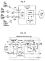
- the TDM based telephone system 900 comprises a plurality of phone devices 920, 925 connected over land lines 902 (a reliable network) to a system 910.
- the system 910 comprises line card 912 for interfacing the land lines 902 with control logic 914, the control logic 914 interfacing with the PSTN 930 and controlling a pool of Full Duplex Handsfree (FDHF) echo cancellers 916.
- FDHF Full Duplex Handsfree
- the TDM based telephone system 900 operates in a similar manner to the telephone system 700 of Figure 7 where a FDHF is allocated from the pool of FDHF 916 for a phone device 925 in speakerphone mode.
- the distributed echo cancelling architecture can also be used to share echo cancelling resources even over reliable networks.
- Voice-Over-IP Voice-Over-IP
- line echo cancellers are typically located in gateways connecting the VoIP networks to traditional networks, such as PSTN, with analogue POTS phones. Echo cancelling is required, as echoes become more noticeable to the user when transmission delays introduced by a network increases. These perceived echoes considerably degrade speech quality.
- FIG. 10 there is shown a block diagram of a packet based distributed Line Echo Canceller 1000 to compensate for line echo 1010.
- the packet based distributed Line Echo Canceller 1000 comprises a satellite gateway 1020 connected over a packet network 1030 to a central gateway 1040.
- the line echo canceller 1000 works in a similar manner as the acoustic echo canceller shown in Figures 4, 5, and 6.
- the near end signal is corrupted by a line echo 1010.
- the satellite gateway 1020 combines the signal Si with the reference signal Ro', which is then transmitted to the central gateway 1040.
- a splitter 1050 in combination with a subtractor 1054 and a line echo estimator and control (LEC) 1052, perform echo cancelling.
- LEC line echo estimator and control
- the VoIP network 1100 comprises a plurality of satellite gateways 1110 connected over a packet network 1120 to a central gateway 1130 which interfaces with the PSTN 1140.
- the central gateway 1130 has a pool of distributed line echo cancellers 1135 (of Figure 10) for line echo cancelling.
- the central gateway 1130 interfaces the VoIP network 1100 to traditional synchronous networks such as the PSTN 1140 or, alternatively, telephones.
- the satellite gateways require costly echo cancelling resources to cancel the line echoes before they enter the packet domain.
- this function can be distributed between the satellite gateways and the central gateway.
- the present invention has the advantage of having the actual line echo cancelling resources located at the central gateway, which is typically more cost tolerant.
Landscapes
- Engineering & Computer Science (AREA)
- Signal Processing (AREA)
- Computer Networks & Wireless Communication (AREA)
- Cable Transmission Systems, Equalization Of Radio And Reduction Of Echo (AREA)
- Telephonic Communication Services (AREA)
Abstract
Description
- This invention relates to echo cancelling and in particular to distributed echo cancelling.
- The present invention will be described in detail with reference to the accompanying drawings, in which like numerals denote like parts, and in which
- Figure 1 is a block diagram of a conventional echo canceller;
- Figure 2 is a block diagram of a conventional full duplex hands free (FDHF) echo canceller for a traditional speakerphone;
- Figure 3 is a block diagram of a conventional packet network based acoustic echo canceller for connection with a packet network;
- Figure 4 is a block diagram of a distributed acoustic echo canceller in accordance with one embodiment of the present invention;
- Figure 5 is a block diagram of the distributed acoustic echo canceller of Figure 4 (a Full Duplex Handsfree (FDHF) structure) in a packet domain interfacing to a synchronous domain;
- Figure 6 is a block diagram of a more detailed view of the phone side of Figure 5 in the packet domain;
- Figure 7 is a block diagram of a telephone system with a distributed echo cancelling architecture;
- Figure 8 is a block diagram of a distributed echo canceller operating over a reliable network;
- Figure 9 is a block diagram of a TDM based telephone system with the distributed echo canceller of Figure 8;
- Figure 10 is a block diagram of a packet based distributed Line Echo Canceller to compensate for line echo; and
- Figure 11 is a block diagram of a VoIP network using distributed line echo cancellers of Figure 10.
-
- The purpose of echo cancelling is to compensate a signal for echoes caused by various sources including feedback from a speaker in close proximity to a microphone. In general, prior art echo cancellers use a reference signal to determine the echoes and accordingly compensate the signal by removing (subtracting) an estimate of the echoes from the signal.
- However, echo cancelling, either acoustic or line, can be relatively expensive, especially in long delay networks, such as packet-based networks. In traditional echo canceller architecture, the delays in the network are compensated by increasing buffer size and thus memory requirements. Unreliable transport media, such as Internet Protocol networks, have an additional problem of packet loss, which can considerably reduce the effectiveness of an echo canceller.
- Referring to Figure 1, there is shown a block diagram of a
conventional echo canceller 100. Theconventional echo canceller 100 comprises an echo estimator andcontrol 110 and asubtractor 120. An input signal (Sin 130) is a combination of an Echo 132 (the echoes) and the near end signal. As is known in the art, the echo estimator andcontrol 110 uses the reference signal (Rout or Rin) 134 and thesubtractor 120 to remove an estimate of the echo from theinput signal 130. The goal of the echo canceller is to create an output signal (Sout 136) that matches the near end signal as closely as possible with the echo sufficiently reduced. - Referring to Figure 2, there is shown a block diagram of a conventional full duplex hands free (FDHF)
echo canceller 200 for a traditional speakerphone. The FDHFecho canceller 200 includes a line echo estimator andcontrol 210 as well as afirst subtractor 215 for cancelling line echo 217 (the echoes) introduced by a network (not shown). An acoustic echo estimator is provided along withcontrol 220 and asecond subtractor 222 for cancellingacoustic echo 224 betweenloudspeaker 226 andmicrophone 228. - Referring to Figure 3, there is shown a block diagram of a conventional packet network based acoustic echo canceller 300 for connection with a
packet network 350. In packet networks, line echo is typically cancelled at IP/PSTN gateways (not shown). The canceller 300 comprises an acoustic echo estimator 300, asubtractor 310, apacketizer 320 and de-packetizer 330. - In the traditional speakerphone, these echo-cancelling resources are located on the phone, which increases the cost for each of the phone sets. These echo-cancelling resources are usually idle, since for most of the time, users are not using the speakerphone feature.
- It is therefore desirable to provide an echo cancelling system, which addresses the shortcomings of providing echo cancelling, noted above.
- A distributed echo cancelling architecture is provided where echo-canceling functions are performed at locations remote from devices receiving signals with echoes. The echo cancelling functions use the input (transmit) signal, which has been corrupted with the echoes at the devices, along with a copy of the reference signal as received at the devices, for echo cancellation. As echo canceller resources are located at a central system and not at each individual device, the echo canceller resources can be shared between the devices.
- It is an aspect of an object of the present invention to reduce the overall cost of a communications system.
- It is a further aspect of an object of the present invention to provide echo cancellers that are independent of network delay and more robust towards packet / frame loss than prior art echo cancellers.
- According to an aspect of the invention, there is provided a communication system, comprising a system having an echo cancelling function for cancelling echoes from at least one signal using a first reference signal; and at least one device that is remote from the system over a network for receiving a second reference signal comprising the first reference signal as modified by network effects due to transmission over the network, for initiating incorporation of the echoes into the second reference signal to form a part of respective one of said at least one signal, and for receiving and transmitting said at least one signal to the system over the network.
- According to a further aspect of the invention, there is provided A method of distributed echo cancelling in a communication system, comprising transmitting a first reference signal to at least one device that is remote over a network; receiving a second reference signal by said at least one device where the second reference signal comprises the first reference signal as modified by network effects due to transmission over the network; initiating incorporation of echoes at said at least one device into the second reference signal to form a part of at least one signal where said at least one signal also has the echoes; receiving said at least one signal over the network; and cancelling the echoes from said at least one signal using the first reference signal.
- Referring to Figure 4, there is shown a block diagram of a distributed
acoustic echo canceller 400 in accordance with one embodiment of the present invention. The distributedacoustic echo canceller 400 comprises asystem 410 with asplitter 412, an acoustic echo estimator andcontrol 414 and asubtractor 416; aphone device 420 with a signal combiner 422, amicrophone 424, and aloudspeaker 426. The acoustic echo estimator andcontrol 414 will be understood by a person of ordinary skill in the art to be an adaptive filter (see for example "Adaptive Filter Theory", 3rd edition. Simon Haykin, Prentice Hall, 1996. ISBN 0-13-322-760-X. - The
system 410, such as a PBX, sends a first reference signal Ro to thephone device 420. The first reference signal Ro is delayed and potentially corrupted by a network 450 (such as packet loss / frame erasure compensation /vocoding / delay jitter) when it arrives at thephone device 420 as a second reference signal Ro'. The second reference signal Ro' is sent to theloudspeaker 426 of thephone device 420. Due to acoustic coupling, a first signal Si (equivalent to Sin), comprising a near end signal (such as a voice signal) and an acoustic echo signal, is picked up at themicrophone 424. This first signal Si, in conjunction with the transmitted signal Ro', is sent back to thesystem 410. - At the
system 410, thesplitter 412 splits the combined signal Si, Ro' and the second reference signal Ro' is used as a reference signal in the acoustic echo estimator andcontrol 414, resulting in echo cancelled signal So. Thesplitter 412 further monitors the incoming signal (Si, Ro') for lost packets and other corruption, and controls the acoustic echo estimator andcontrol 414 accordingly. - Where the
phone device 412 further comprises a compression device (not shown), the combined signal is also decompressed in thesplitter 412 as the acoustic echo estimator andcontrol 414 operates on uncompressed samples. Some speech vocoders, such as for example G.729, have their own packet loss compensation / frame erasure schemes. Thus, if there is packet loss insend path 460, any adaptation of the acoustic echo estimator andcontrol 414 is frozen to prevent divergence of thedistributed echo canceller 400 in packet loss situations. - The
distributed echo canceller 400 is thus not affected by any network delays as the second reference signal Ro' (and not Ro) is used as the reference signal. Furthermore, non-linear effects in receivepath 470 such as packet loss are not relevant as there is an exact copy of the second reference signal Ro', after network effects, that is sent to theloudspeaker 426. Packet loss in the send path 460 (Si + Ro') is determined by the protocol of thenetwork 450. Consequently, this echo cancelling structure is not dependent on network delay and can be made more robust with regard to packet loss / frame erasure. - Signal corruption over the send path is handled by the network protocol (i.e. packet loss indication). Adaptation of the echo canceller on lost packets is compensated by a packet loss / frame erasure compensation scheme. An example of such a scheme for PCM voice is as follows:


- Several packet loss schemes are known in the art, such as zero insertion, repeat of previous packet, noise insertion etc. One example of such a scheme applied to echo canceling is Canadian Patent Application No. 2331228 entitled "PACKET LOSS COMPENSATION METHOD USING INJECTION OF SPECTRALLY SHAPED NOISE" by Goubran, Schulz et al".
- Referring to Figure 5, there is shown a block diagram of the distributed
acoustic echo canceller 400 of Figure 4 (a Full Duplex Handsfree (FDHF) structure) in apacket domain 500 interfacing to a synchronous domain 510. Thepacket domain 500 includes voice over IP (VoIP) networks. The synchronous domain 510 includes time division multiplexed (TDM) networks such as the PSTN. The phone device 420 (phone side) is as shown in Figure 4.Rate adapters packet domain 500 with the synchronous domain 510. Therate adapter 522 in the receive path may also contain a speech compression unit, if speech compression is required. A line echo canceller (530 and 535) is used in the synchronous domain 510 to cancelline echo 550. - Referring to Figure 6, there is shown a block diagram of a more detailed view of the phone side of Figure 5 in the
packet domain 500 such as a VoIP (Voice-Over-IP) network. A de-packetizer 600 converts packet data into the second reference signal Ro' that is sent to theloudspeaker 426. The de-packetizer 600 compensates for network effects such as lost packets / frame erasure and clock drift (sampling rate adjustment). As a result of these network effects, received packets may be corrupted and are consequently indicated by the second reference signal Ro'.Packetizer 610 converts the second reference signal Ro' sent to theloudspeaker 426 back into packet data for apacket combiner 620.Packetizer 630 packetizes the signal Si received from themicrophone 424. Both packets are then combined by thepacket combiner 620 and sent over thenetwork 450. Thepacketizers - It will be understood by those skilled in the art that voice decompression may be performed by the de-packetizer 600 and voice compression by the
packetizers - Referring to Figure 7, there is shown a block diagram of a
telephone system 700 with a distributed echo cancelling architecture. Thetelephone system 700 comprises asystem 710 having control logic 715 for controlling a pool of Full Duplex Handsfree (FDHF) echocancellers 720; and a plurality ofphone devices switch 710 over anetwork 750. Onesuch phone device 740 is shown in a speakerphone mode. Theswitch 710 is, for example, an IP PBX switch. - In this
telephone system 700, by default all of thephone devices - When the user hits a speakerphone key, the
phone device 740 is put into speakerphone mode as shown in Figure 7. In the speakerphone mode, a combined signal Si, Ro', which comprises a received reference signal Ro' and a microphone signal Si, is sent back to theswitch 710 over thenetwork 750. At theswitch 710, a speakerphone resource is allocated out of the pool ofFDHF 720 to perform echo cancelling functions on the combined signal Si, Ro'. - As the number of active speakerphone calls is generally much less than the number of phone devices attached to a telephone system, the speakerphone resources of the
telephone system 700 are shared among the users. Thus, a cost reduction is achieved. Furthermore, the speakerphone echo cancelling resources at the switch may be of a higher quality than echo cancelling resources at each device as the cost is mitigated over more than one user. - Referring to Figure 8, there is shown a block diagram of a distributed
echo canceller 800 operating over areliable network 810. The distributedecho canceller 800 comprises a phone device 802, and asystem 804 with asubtractor 808 and an acoustic echo estimator and control (AEC) 806. Thereliable network 810 is, for example, a TDM connection. - When the
network 810 is reliable and the delay is deterministic, reference signal Ro' is a delayed version of a reference signal Ro. Thus, it is not necessary to send the reference signal Ro' back oversend path 820, especially when the network delay is short. Instead of the reference signal Ro', the acoustic estimator and control 806 uses the reference signal Ro. - Referring to Figure 9, there is shown a block diagram of a TDM based telephone system 900 with the distributed echo canceller of Figure 8. The TDM based telephone system 900 comprises a plurality of
phone devices system 910. Thesystem 910 comprisesline card 912 for interfacing theland lines 902 withcontrol logic 914, thecontrol logic 914 interfacing with thePSTN 930 and controlling a pool of Full Duplex Handsfree (FDHF) echo cancellers 916. The TDM based telephone system 900 operates in a similar manner to thetelephone system 700 of Figure 7 where a FDHF is allocated from the pool of FDHF 916 for aphone device 925 in speakerphone mode. Thus, the distributed echo cancelling architecture can also be used to share echo cancelling resources even over reliable networks. - In VolP (Voice-Over-IP) networks, line echo cancellers are typically located in gateways connecting the VoIP networks to traditional networks, such as PSTN, with analogue POTS phones. Echo cancelling is required, as echoes become more noticeable to the user when transmission delays introduced by a network increases. These perceived echoes considerably degrade speech quality.
- Referring to Figure 10, there is shown a block diagram of a packet based distributed
Line Echo Canceller 1000 to compensate forline echo 1010. The packet based distributedLine Echo Canceller 1000 comprises asatellite gateway 1020 connected over apacket network 1030 to acentral gateway 1040. Theline echo canceller 1000 works in a similar manner as the acoustic echo canceller shown in Figures 4, 5, and 6. The near end signal is corrupted by aline echo 1010. Thesatellite gateway 1020 combines the signal Si with the reference signal Ro', which is then transmitted to thecentral gateway 1040. At thecentral gateway 1040, asplitter 1050, in combination with asubtractor 1054 and a line echo estimator and control (LEC) 1052, perform echo cancelling. - Referring to Figure 11, there is shown a block diagram of a
VoIP network 1100 using distributed line echo cancellers of Figure 10. TheVoIP network 1100 comprises a plurality ofsatellite gateways 1110 connected over apacket network 1120 to acentral gateway 1130 which interfaces with thePSTN 1140. Thecentral gateway 1130 has a pool of distributed line echo cancellers 1135 (of Figure 10) for line echo cancelling. Thecentral gateway 1130 interfaces theVoIP network 1100 to traditional synchronous networks such as thePSTN 1140 or, alternatively, telephones. - Typically the satellite gateways require costly echo cancelling resources to cancel the line echoes before they enter the packet domain. With distributed echo cancelling, however, this function can be distributed between the satellite gateways and the central gateway. The present invention has the advantage of having the actual line echo cancelling resources located at the central gateway, which is typically more cost tolerant.
- Although preferred embodiments of the invention have been described herein, it will be understood by those skilled in the art that variations may be made thereto without departing from the scope of the invention or the appended claims.
Claims (4)
- A distributed echo canceller, comprising
a system for applying a signal (Ro) to a network, and for receiving a signal (Si,Ro') from said network and cancelling echoes therefrom using a modified version (Ro') of said signal (Ro); and
at least one device that is remote from the system over said network for (i) receiving and outputting said modified version (Ro') of the signal (Ro) corrupted by transmission over the network, (ii) receiving a signal (Si) containing an echo of said modified signal (Ro'), and (iii) combining and transmitting said signals (Si, Ro') over the network to said system for echo cancellation of said signal (Si) using said modified signal (Ro'). - The distributed echo canceller of claim 1, wherein the system further comprises a splitter, a subtractor, and an echo estimator and control.
- The distributed echo canceller of claim 2, wherein said at least one device is a handsfree device.
- A method of distributed echo cancelling, comprising transmitting a first reference signal from a system to a network; receiving a second reference signal by at least one device that is remote from said system over said network, wherein the second reference signal comprises the first reference signal as modified by network effects due to transmission over the network;
outputting said second reference signal from said at least one device;
receiving within said at least one device a further signal containing an echo of said second reference signal;
combining said further signal and said second reference signal at said at least one device;
transmitting said combined signal from said at ieast one device to said network;
receiving within said system the combined signal;
splitting said second reference signal from said further signal; and
cancelling the echoes from said further signal using the second reference signal.
Applications Claiming Priority (2)
| Application Number | Priority Date | Filing Date | Title |
|---|---|---|---|
| GB0212591 | 2002-05-31 | ||
| GB0212591A GB2389287B (en) | 2002-05-31 | 2002-05-31 | Distributed echo cancelling |
Publications (2)
| Publication Number | Publication Date |
|---|---|
| EP1367738A1 true EP1367738A1 (en) | 2003-12-03 |
| EP1367738B1 EP1367738B1 (en) | 2006-08-16 |
Family
ID=9937787
Family Applications (1)
| Application Number | Title | Priority Date | Filing Date |
|---|---|---|---|
| EP03253161A Expired - Lifetime EP1367738B1 (en) | 2002-05-31 | 2003-05-21 | Distributed echo cancelling |
Country Status (7)
| Country | Link |
|---|---|
| US (2) | US7085374B2 (en) |
| EP (1) | EP1367738B1 (en) |
| KR (1) | KR100557752B1 (en) |
| CN (1) | CN1494231A (en) |
| CA (1) | CA2430030C (en) |
| DE (1) | DE60307540T2 (en) |
| GB (1) | GB2389287B (en) |
Cited By (1)
| Publication number | Priority date | Publication date | Assignee | Title |
|---|---|---|---|---|
| WO2013121306A3 (en) * | 2012-02-14 | 2013-11-07 | Koninklijke Philips N.V. | Audio signal processing in a communication system |
Families Citing this family (21)
| Publication number | Priority date | Publication date | Assignee | Title |
|---|---|---|---|---|
| US7002897B2 (en) * | 2003-04-28 | 2006-02-21 | Solarflare Communications, Inc. | Multiple channel interference cancellation |
| US7433463B2 (en) * | 2004-08-10 | 2008-10-07 | Clarity Technologies, Inc. | Echo cancellation and noise reduction method |
| JP2006108777A (en) | 2004-09-30 | 2006-04-20 | Toshiba Corp | Telephone terminal, telephone system using the telephone terminal, and telephone terminal control method |
| US8599704B2 (en) | 2007-01-23 | 2013-12-03 | Microsoft Corporation | Assessing gateway quality using audio systems |
| US8396206B2 (en) * | 2007-02-15 | 2013-03-12 | Infineon Technologies Ag | Multi-channel communication device and methods for reducing echoes by inserting a training sequence under a spectral mask |
| US8213597B2 (en) * | 2007-02-15 | 2012-07-03 | Infineon Technologies Ag | Audio communication device and methods for reducing echoes by inserting a training sequence under a spectral mask |
| US8090077B2 (en) * | 2007-04-02 | 2012-01-03 | Microsoft Corporation | Testing acoustic echo cancellation and interference in VoIP telephones |
| US20090017877A1 (en) * | 2007-07-11 | 2009-01-15 | Pi-Fen Lin | Wi-fi phone with hands-free feature |
| US8223959B2 (en) * | 2007-07-31 | 2012-07-17 | Hewlett-Packard Development Company, L.P. | Echo cancellation in which sound source signals are spatially distributed to all speaker devices |
| US8433058B2 (en) * | 2008-08-08 | 2013-04-30 | Avaya Inc. | Method and system for distributed speakerphone echo cancellation |
| US8462193B1 (en) * | 2010-01-08 | 2013-06-11 | Polycom, Inc. | Method and system for processing audio signals |
| CN103348700B (en) * | 2011-02-22 | 2016-09-07 | 蓝博士公司 | The system and method eliminated for the acoustic echo of wireless microphone and loudspeaker |
| US8879438B2 (en) | 2011-05-11 | 2014-11-04 | Radisys Corporation | Resource efficient acoustic echo cancellation in IP networks |
| US9779731B1 (en) * | 2012-08-20 | 2017-10-03 | Amazon Technologies, Inc. | Echo cancellation based on shared reference signals |
| US9674368B2 (en) * | 2013-03-19 | 2017-06-06 | Koninklijke Philips N.V. | Method and apparatus for audio processing |
| US9270830B2 (en) * | 2013-08-06 | 2016-02-23 | Telefonaktiebolaget L M Ericsson (Publ) | Echo canceller for VOIP networks |
| US9420114B2 (en) * | 2013-08-06 | 2016-08-16 | Telefonaktiebolaget Lm Ericsson (Publ) | Echo canceller for VOIP networks |
| US9319532B2 (en) | 2013-08-15 | 2016-04-19 | Cisco Technology, Inc. | Acoustic echo cancellation for audio system with bring your own devices (BYOD) |
| CN103716478B (en) * | 2013-12-11 | 2016-04-06 | 电子科技大学 | bidirectional echo cancellation method |
| US10147441B1 (en) | 2013-12-19 | 2018-12-04 | Amazon Technologies, Inc. | Voice controlled system |
| US10439673B2 (en) * | 2017-12-11 | 2019-10-08 | Mitel Cloud Services, Inc. | Cloud-based acoustic echo canceller |
Citations (2)
| Publication number | Priority date | Publication date | Assignee | Title |
|---|---|---|---|---|
| US5875246A (en) * | 1996-10-29 | 1999-02-23 | Xinex Networks Inc. | Distributed audio signal processing in a network experiencing transmission delay |
| US6081732A (en) * | 1995-06-08 | 2000-06-27 | Nokia Telecommunications Oy | Acoustic echo elimination in a digital mobile communications system |
Family Cites Families (8)
| Publication number | Priority date | Publication date | Assignee | Title |
|---|---|---|---|---|
| FI106489B (en) * | 1996-06-19 | 2001-02-15 | Nokia Networks Oy | Eco-muffler and non-linear processor for an eco extinguisher |
| US5856970A (en) * | 1996-08-05 | 1999-01-05 | Motorola, Inc. | Multi-channel echo cancellation method and apparatus |
| US6147979A (en) * | 1997-08-12 | 2000-11-14 | Lucent Technologies, Inc. | System and method for echo cancellation in a communication system |
| US6570985B1 (en) * | 1998-01-09 | 2003-05-27 | Ericsson Inc. | Echo canceler adaptive filter optimization |
| US6724736B1 (en) * | 2000-05-12 | 2004-04-20 | 3Com Corporation | Remote echo cancellation in a packet based network |
| US6434235B1 (en) * | 2000-08-01 | 2002-08-13 | Lucent Technologies Inc. | Acoustic echo canceler |
| US6745018B1 (en) * | 2000-09-29 | 2004-06-01 | Intel Corporation | Active cancellation of a wireless coupled transmit signal |
| US7283585B2 (en) * | 2002-09-27 | 2007-10-16 | Broadcom Corporation | Multiple data rate communication system |
-
2002
- 2002-05-31 GB GB0212591A patent/GB2389287B/en not_active Expired - Lifetime
-
2003
- 2003-05-21 DE DE60307540T patent/DE60307540T2/en not_active Expired - Lifetime
- 2003-05-21 EP EP03253161A patent/EP1367738B1/en not_active Expired - Lifetime
- 2003-05-26 CA CA002430030A patent/CA2430030C/en not_active Expired - Lifetime
- 2003-05-29 US US10/447,857 patent/US7085374B2/en not_active Expired - Lifetime
- 2003-05-30 KR KR1020030034671A patent/KR100557752B1/en not_active Expired - Fee Related
- 2003-05-30 CN CNA031407048A patent/CN1494231A/en active Pending
-
2006
- 2006-06-28 US US11/476,926 patent/US20070071230A1/en not_active Abandoned
Patent Citations (2)
| Publication number | Priority date | Publication date | Assignee | Title |
|---|---|---|---|---|
| US6081732A (en) * | 1995-06-08 | 2000-06-27 | Nokia Telecommunications Oy | Acoustic echo elimination in a digital mobile communications system |
| US5875246A (en) * | 1996-10-29 | 1999-02-23 | Xinex Networks Inc. | Distributed audio signal processing in a network experiencing transmission delay |
Cited By (4)
| Publication number | Priority date | Publication date | Assignee | Title |
|---|---|---|---|---|
| WO2013121306A3 (en) * | 2012-02-14 | 2013-11-07 | Koninklijke Philips N.V. | Audio signal processing in a communication system |
| CN104126297A (en) * | 2012-02-14 | 2014-10-29 | 皇家飞利浦有限公司 | Audio Signal Processing in Communication Systems |
| US9826085B2 (en) | 2012-02-14 | 2017-11-21 | Koninklijke Philips N.V. | Audio signal processing in a communication system |
| EP2815566B1 (en) | 2012-02-14 | 2018-03-14 | Koninklijke Philips N.V. | Audio signal processing in a communication system |
Also Published As
| Publication number | Publication date |
|---|---|
| DE60307540T2 (en) | 2007-08-09 |
| CA2430030C (en) | 2007-02-06 |
| EP1367738B1 (en) | 2006-08-16 |
| US20030223574A1 (en) | 2003-12-04 |
| US7085374B2 (en) | 2006-08-01 |
| KR100557752B1 (en) | 2006-03-07 |
| GB2389287A (en) | 2003-12-03 |
| US20070071230A1 (en) | 2007-03-29 |
| KR20030094040A (en) | 2003-12-11 |
| CA2430030A1 (en) | 2003-11-30 |
| CN1494231A (en) | 2004-05-05 |
| GB0212591D0 (en) | 2002-07-10 |
| GB2389287B (en) | 2005-11-23 |
| DE60307540D1 (en) | 2006-09-28 |
Similar Documents
| Publication | Publication Date | Title |
|---|---|---|
| EP1367738B1 (en) | Distributed echo cancelling | |
| US8976715B2 (en) | System and method for operating a packet voice far-end echo cancellation system | |
| US6324170B1 (en) | Echo controller with compensation for variable delay networks | |
| US8929263B2 (en) | Echo mitigation in the presence of variable delays due to adaptive jitter buffers | |
| US9794417B2 (en) | Packet voice system with far-end echo cancellation | |
| US7970124B2 (en) | Adaptive gain control based on echo canceller performance information | |
| US10848201B2 (en) | Cloud-based acoustic echo canceller | |
| US6580696B1 (en) | Multi-adaptation for a voice packet based | |
| US7149305B2 (en) | Combined sidetone and hybrid balance | |
| US7283543B1 (en) | System and method for operating echo cancellers with networks having insufficient levels of echo return loss | |
| EP2405587B1 (en) | Echo canceller | |
| US7039179B1 (en) | Echo reduction for a headset or handset | |
| US8280023B2 (en) | Communication conference system, voice changing device, and signal converting adaptor | |
| EP1434416B1 (en) | Packet voice system with far-end echo cancellation | |
| US6618479B1 (en) | Echo canceler |
Legal Events
| Date | Code | Title | Description |
|---|---|---|---|
| PUAI | Public reference made under article 153(3) epc to a published international application that has entered the european phase |
Free format text: ORIGINAL CODE: 0009012 |
|
| AK | Designated contracting states |
Kind code of ref document: A1 Designated state(s): AT BE BG CH CY CZ DE DK EE ES FI FR GB GR HU IE IT LI LU MC NL PT RO SE SI SK TR |
|
| AX | Request for extension of the european patent |
Extension state: AL LT LV MK |
|
| 17P | Request for examination filed |
Effective date: 20040121 |
|
| AKX | Designation fees paid |
Designated state(s): DE FR GB |
|
| GRAP | Despatch of communication of intention to grant a patent |
Free format text: ORIGINAL CODE: EPIDOSNIGR1 |
|
| GRAS | Grant fee paid |
Free format text: ORIGINAL CODE: EPIDOSNIGR3 |
|
| GRAA | (expected) grant |
Free format text: ORIGINAL CODE: 0009210 |
|
| AK | Designated contracting states |
Kind code of ref document: B1 Designated state(s): DE FR GB |
|
| REG | Reference to a national code |
Ref country code: GB Ref legal event code: FG4D |
|
| REF | Corresponds to: |
Ref document number: 60307540 Country of ref document: DE Date of ref document: 20060928 Kind code of ref document: P |
|
| ET | Fr: translation filed | ||
| PLBE | No opposition filed within time limit |
Free format text: ORIGINAL CODE: 0009261 |
|
| STAA | Information on the status of an ep patent application or granted ep patent |
Free format text: STATUS: NO OPPOSITION FILED WITHIN TIME LIMIT |
|
| 26N | No opposition filed |
Effective date: 20070518 |
|
| REG | Reference to a national code |
Ref country code: FR Ref legal event code: PLFP Year of fee payment: 14 |
|
| REG | Reference to a national code |
Ref country code: FR Ref legal event code: PLFP Year of fee payment: 15 |
|
| REG | Reference to a national code |
Ref country code: FR Ref legal event code: PLFP Year of fee payment: 16 |
|
| PGFP | Annual fee paid to national office [announced via postgrant information from national office to epo] |
Ref country code: GB Payment date: 20220401 Year of fee payment: 20 Ref country code: FR Payment date: 20220408 Year of fee payment: 20 Ref country code: DE Payment date: 20220329 Year of fee payment: 20 |
|
| REG | Reference to a national code |
Ref country code: DE Ref legal event code: R071 Ref document number: 60307540 Country of ref document: DE |
|
| REG | Reference to a national code |
Ref country code: GB Ref legal event code: PE20 Expiry date: 20230520 |
|
| PG25 | Lapsed in a contracting state [announced via postgrant information from national office to epo] |
Ref country code: GB Free format text: LAPSE BECAUSE OF EXPIRATION OF PROTECTION Effective date: 20230520 |