EP1367573A1 - Optical pickup device - Google Patents
Optical pickup device Download PDFInfo
- Publication number
- EP1367573A1 EP1367573A1 EP03011917A EP03011917A EP1367573A1 EP 1367573 A1 EP1367573 A1 EP 1367573A1 EP 03011917 A EP03011917 A EP 03011917A EP 03011917 A EP03011917 A EP 03011917A EP 1367573 A1 EP1367573 A1 EP 1367573A1
- Authority
- EP
- European Patent Office
- Prior art keywords
- coil
- lens holder
- pickup device
- pair
- objective lens
- Prior art date
- Legal status (The legal status is an assumption and is not a legal conclusion. Google has not performed a legal analysis and makes no representation as to the accuracy of the status listed.)
- Granted
Links
- 230000003287 optical effect Effects 0.000 title claims abstract description 80
- 239000000758 substrate Substances 0.000 claims description 119
- 239000000725 suspension Substances 0.000 claims description 57
- 230000005484 gravity Effects 0.000 claims description 13
- 230000005415 magnetization Effects 0.000 claims description 12
- 238000010586 diagram Methods 0.000 description 9
- XEEYBQQBJWHFJM-UHFFFAOYSA-N Iron Chemical compound [Fe] XEEYBQQBJWHFJM-UHFFFAOYSA-N 0.000 description 2
- 238000005096 rolling process Methods 0.000 description 2
- 229910052742 iron Inorganic materials 0.000 description 1
- 230000007257 malfunction Effects 0.000 description 1
- 239000002184 metal Substances 0.000 description 1
- 229910052751 metal Inorganic materials 0.000 description 1
Images


Classifications
-
- G—PHYSICS
- G11—INFORMATION STORAGE
- G11B—INFORMATION STORAGE BASED ON RELATIVE MOVEMENT BETWEEN RECORD CARRIER AND TRANSDUCER
- G11B7/00—Recording or reproducing by optical means, e.g. recording using a thermal beam of optical radiation by modifying optical properties or the physical structure, reproducing using an optical beam at lower power by sensing optical properties; Record carriers therefor
- G11B7/12—Heads, e.g. forming of the optical beam spot or modulation of the optical beam
-
- G—PHYSICS
- G11—INFORMATION STORAGE
- G11B—INFORMATION STORAGE BASED ON RELATIVE MOVEMENT BETWEEN RECORD CARRIER AND TRANSDUCER
- G11B7/00—Recording or reproducing by optical means, e.g. recording using a thermal beam of optical radiation by modifying optical properties or the physical structure, reproducing using an optical beam at lower power by sensing optical properties; Record carriers therefor
- G11B7/08—Disposition or mounting of heads or light sources relatively to record carriers
- G11B7/09—Disposition or mounting of heads or light sources relatively to record carriers with provision for moving the light beam or focus plane for the purpose of maintaining alignment of the light beam relative to the record carrier during transducing operation, e.g. to compensate for surface irregularities of the latter or for track following
- G11B7/0925—Electromechanical actuators for lens positioning
- G11B7/093—Electromechanical actuators for lens positioning for focusing and tracking
-
- G—PHYSICS
- G11—INFORMATION STORAGE
- G11B—INFORMATION STORAGE BASED ON RELATIVE MOVEMENT BETWEEN RECORD CARRIER AND TRANSDUCER
- G11B7/00—Recording or reproducing by optical means, e.g. recording using a thermal beam of optical radiation by modifying optical properties or the physical structure, reproducing using an optical beam at lower power by sensing optical properties; Record carriers therefor
- G11B7/08—Disposition or mounting of heads or light sources relatively to record carriers
- G11B7/09—Disposition or mounting of heads or light sources relatively to record carriers with provision for moving the light beam or focus plane for the purpose of maintaining alignment of the light beam relative to the record carrier during transducing operation, e.g. to compensate for surface irregularities of the latter or for track following
- G11B7/0925—Electromechanical actuators for lens positioning
- G11B7/0933—Details of stationary parts
-
- G—PHYSICS
- G11—INFORMATION STORAGE
- G11B—INFORMATION STORAGE BASED ON RELATIVE MOVEMENT BETWEEN RECORD CARRIER AND TRANSDUCER
- G11B7/00—Recording or reproducing by optical means, e.g. recording using a thermal beam of optical radiation by modifying optical properties or the physical structure, reproducing using an optical beam at lower power by sensing optical properties; Record carriers therefor
- G11B7/08—Disposition or mounting of heads or light sources relatively to record carriers
- G11B7/09—Disposition or mounting of heads or light sources relatively to record carriers with provision for moving the light beam or focus plane for the purpose of maintaining alignment of the light beam relative to the record carrier during transducing operation, e.g. to compensate for surface irregularities of the latter or for track following
- G11B7/0925—Electromechanical actuators for lens positioning
- G11B7/0935—Details of the moving parts
-
- G—PHYSICS
- G11—INFORMATION STORAGE
- G11B—INFORMATION STORAGE BASED ON RELATIVE MOVEMENT BETWEEN RECORD CARRIER AND TRANSDUCER
- G11B7/00—Recording or reproducing by optical means, e.g. recording using a thermal beam of optical radiation by modifying optical properties or the physical structure, reproducing using an optical beam at lower power by sensing optical properties; Record carriers therefor
- G11B7/08—Disposition or mounting of heads or light sources relatively to record carriers
- G11B7/09—Disposition or mounting of heads or light sources relatively to record carriers with provision for moving the light beam or focus plane for the purpose of maintaining alignment of the light beam relative to the record carrier during transducing operation, e.g. to compensate for surface irregularities of the latter or for track following
- G11B7/0925—Electromechanical actuators for lens positioning
- G11B7/0932—Details of sprung supports
Definitions
- the present invention relates to a pickup device of a disc drive for optically writing and reading information on an optical disc and, more particularly, to a pickup device suitable for a thin disc drive.
- a disc drive for recording information on and reproducing information from an optical disc such as a CD (Compact Disc) and a DVD (Digital Video Disc) includes an optical pickup device.
- the pickup device performs a focus control for controlling a distance between an objective lens and an information recording surface of the optical disc and performs a tracking control for controlling the objective lens to follow an information track of the optical disc.
- the pickup device directs a laser beam, which is emitted from a light source such as a laser diode, to the objective lens by using predetermined optical system components, and irradiates the laser beam onto the information recording surface of the optical disc via the objective lens.
- a light source such as a laser diode
- the objective lens is positioned to oppose to the optical disc.
- a laser beam from the light source is guided by the optical system components to a position below the objective lens along an optical path provided in parallel with the optical disc.
- the laser beam is changed its path by a raise-up mirror placed under the objective lens to a vertical direction, that is, the direction of the objective lens, and the laser beam reaches the objective lens.
- the objective lens is mounted on a lens holder and coil substrates are mounted on the lens holder.
- the lens holder is moved vertically and horizontally with respect to the optical disc by applying driving current to the coil substrates in a magnetic field formed by the magnets which are placed close to each other, so that the focus control and the tracking control are performed.
- An example of such a pickup device is described in Japanese Patent Laid-Open under No. 2001-229557.
- the optical path of a laser beam from the laser light source cannot be arranged at the same height level as the coil substrates in the horizontal direction. Namely, since the paired coil substrates are positioned on both sides of the objective lens, the coil substrates become obstacles and prevent a laser beam from being guided to the position below the objective lens at the same height level as the coil substrates . For this reason, in the pickup device described in Japanese Patent Laid-Open under No. 2001-229557, for example, the optical path of a laser beam is placed below the lens holder. Namely, the optical path is arranged such that the laser beam is directed to the position below the objective lens at a lower level than the coil substrates and then directed to the objective lens by the raise-up mirror.
- the whole height (thickness in the vertical direction) of the pickup increases.
- a thin drive device such as a drive device mounted in a notebook-type personal computer
- a thin pickup device has to be used and thus the above thick pickup device cannot be used.
- the present invention is devised in view of the above-described point, and its object is to provide a thin pickup device suitable for use in a thin drive device.
- a pickup device including: an actuator including an objective lens; and an optical system for directing a light beam, emitted by a light source, to a position below the objective lens, wherein the optical system is placed at a same height level as the actuator, the actuator includes a lens holder for holding the objective lens and a pair of coil substrates mounted on sides of the lens holder so as to be partially opposed to each other, and the optical system extends to the position below the objective lens through a space in which the pair of coil substrates are not opposed to each other.
- the above pickup device is used in a drive device and the like of an optical disc and is opposed to the optical disc to irradiate a light beam from a light source onto an information recording surface of the optical disc.
- the pickup device has the actuator including the objective lens for condensing a light beam on the information recording surface of the optical disc, and irradiation of a light beam on the optical disc is controlled by moving the objective lens.
- the pickup device has the optical system for directing a light beam, which is emitted from the light source, to a position below the objective lens. The optical system is placed at the same height level as the actuator.
- the whole pickup can be smaller in thickness, and it is possible to obtain a pickup device suitable for a thin drive device. Moreover, since the optical system is placed below the objective lens through the space in which the coil substrates are not opposed to each other, the coil substrates do not interfere with the arrangement of the optical system, thereby readily arranging the optical system at the same height level as the actuator.
- the pair of coil substrates may be partially opposed to each other with being shifted by a predetermined distance to opposite directions in a tracking direction of an optical disc opposed to the objective lens. Hence, it is possible to place the optical systembelow the objective lens with maintaining the balance of the whole lens holder having the pair of coil substrates.
- the actuator may include an actuator base having a pair of yokes, and a pair of magnets fixed on the pair of yokes, wherein each of the pair of magnets positioned to be opposed to each of the paired coil substrates. According to this feature, driving current is applied to the coils on the coil substrates in a magnetic field formed by the magnets, so that the objective lens is moved to perform focus control and tracking control.
- the objective lens may be placed on the lens holder so as to be closer to the optical system than a center of gravity of the lens holder.
- the arrangement of the optical system can reduce a shifting amount of the coil substrates mounted on the lens holder.
- Each of the pair of the coil substrates may include a tracking coil and a focus coil formed in parallel along a horizontal direction of the coil substrate, and the pair of the coil substrates may be opposed to each other only on an area where the focus coil is formed.
- the pair of the coil substrates may include a pair of bumps in the area where the focus coil is formed, and the lens holder may further include connecting wires for electrically connecting the bumps on the paired coil substrates.
- the bumps may be formed as conductive lands of the substrate. Hence, the coil substrates can be connected to each other via short connecting wires in an area having the opposed coil substrates.
- Each of the pair of the magnets may have a magnetization pattern having a north pole area and a south pole area on both sides of a boundary area of substantially L-shaped.
- the boundary area may have a vertically extending area which intersects the tracking coil of the coil substrate in a vertical direction, and the boundary area may have a horizontally extending area which intersects the focus coil of the coil substrate in a horizontal direction. According to this embodiment, it is possible to accurately perform tracking control and focus control by applying driving current to the coils and a magnetic field formed by the magnets.
- the pickup device may further include a plurality of suspension wires which are fixed on the actuator base and the coil substrates mounted on the lens holder and movably supports the lens holder and the coil substrate, wherein a plurality of positions at which the suspension wires are fixed on the actuator base have a horizontal distance smaller than that of a plurality of positions for fixing the suspension wires on the coil substrate .
- the suspension wires can be fixed on the coil substrates which are shifted and opposed to each other.
- a midpoint of a line connecting the positions at which the suspension wires are fixed on the coil substrate may coincide with a center of gravity of the lens holder.
- the lens holder can be supported by the suspension wires with preferred balance.
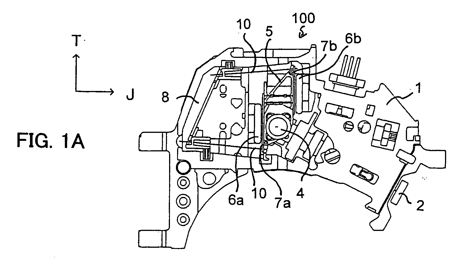
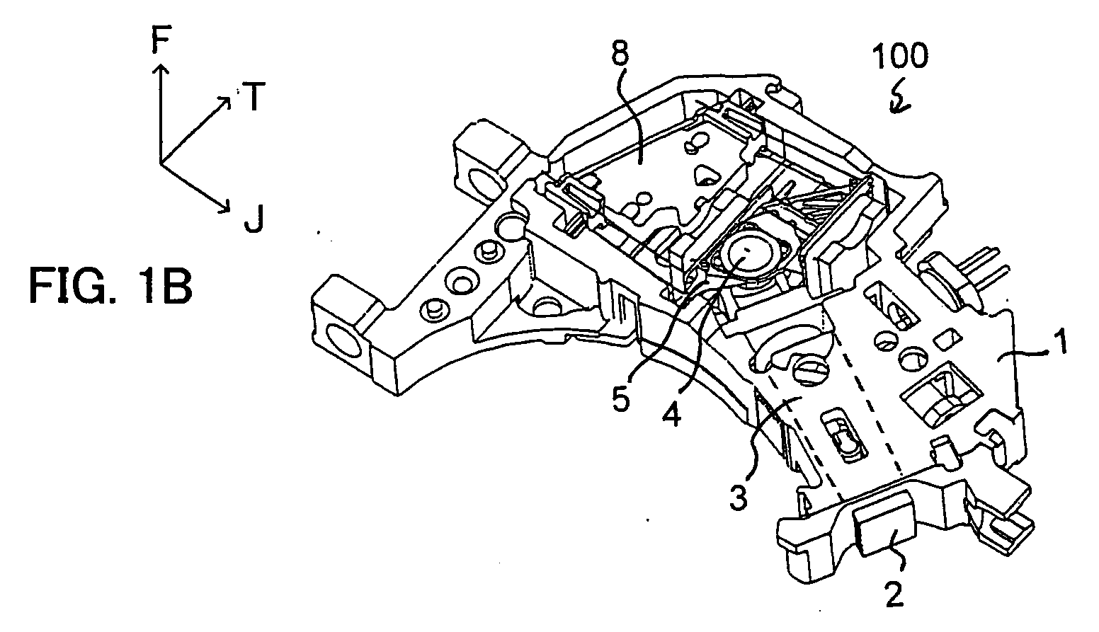
- FIGS. 1A to 1C show the configuration of a pickup device according to an embodiment of the present invention.
- FIG. 1A is a top view of a pickup device 100
- FIG. 1B is a perspective view of the pickup device 100
- FIG. 1C is a bottom plan view of the pickup device 100.
- the pickup device 100 has various components mounted on a body 1.
- An actuator base 8 is fixed on the body 1, and the actuator base 8 supports a lens holder 5 movably in a focusing direction F and a tracking direction T by using four suspension wires 10.
- the lens holder 5 has coil substrates 7a and 7b mounted on the opposing sides thereof and an objective lens 4 mounted on the top surface.
- Magnets 6a and 6b are fixed on the body 1 so as to be respectively opposed to the paired coil substrates 7a and 7b mounted on the lens holder 5.
- the paired magnets 6a and 6b are fixed so as to be opposed to each other, and a magnetic field is created in a space between the magnets 6a and 6b in accordance with the magnetization patterns of the magnets 6a and 6b.
- the lens holder 5 having the coil substrates 7a and 7b on the sides is placed in the magnetic field created by the paired magnets 6a and 6b.
- the lens holder 5 when a predetermined driving current is applied to a focus coil and a tracking coil that are formed on the coil substrates 7a and 7b, the lens holder 5 is moved in the focusing direction F and the tracking direction T due to force generated by the currents in the coils and the magnetic field. Due to the movement of the lens holder 5, the objective lens 4 on the lens holder 5 is moved to perform the focus control and the tracking control.
- a laser light source 2 is mounted on an end of the body 1.
- a laser beam emitted from the laser light source 2 passes through an optical path 3, which is constituted by an optical system arranged in the body 1, and reaches the position below the objective lens 4.
- a raise-up mirror 9 is placed below the objective lens. The raise-up mirror 9 changes the path of the laser beam upward and the laser beam passes through the objective lens 4 upwardly from below.
- An optical disc is placed above the objective lens 4, and the objective lens 4 condenses the laser beam on the information recording surface of the optical disc.
- FIG. 2A is a top view of the actuator
- FIG. 2B is a perspective view of the actuator
- FIG. 2C is a bottom plan view of the actuator.
- the actuator 50 is a mechanism for moving the objective lens 4 in the focusing direction F and the trackingdirectionT, and includes the actuator base 8, the lens holder 5, the paired magnets 6a and 6b, and the paired coil substrates 7a and 7b mounted on the lens holder 5.
- the actuator base 8 is fixed on the body 1 of the pickup device 100. Further, a pair of yokes 11 is formed on the body 1, and the magnets 6a and 6b are fixed inside the yokes 11. In the pickup device 100 of the present invention, the paired yokes 11 are not completely opposed to each other but are displaced from each other in the tracking direction T. This arrangement is made to provide a space for arranging an optical path (optical system) 3 indicated by broken lines in FIG. 2A. The magnets 6a and 6b are mounted inside of the yokes 11, and hence a magnetic field is created in a space between the paired magnets 6a and 6b.
- the lens holder 5 is supported by the four suspension wires 10.
- the lens holder 5 is supported by elasticity of the suspension wires 10 so as to be moved in the focusing direction F and the tracking direction T.
- the objective lens 4 is mounted on the lens holder 5.
- driving current to the focus coil and the tracking coil on the coil substrates 7a and 7b, which are mounted on the lens holder 5, in a magnetic field created by the paired magnets 6a and 6b force is applied to the coil substrates 7a and 7b as well as the lens holder 5 integrated with the coil substrates 7a and 7b in the focusing direction F and the tracking direction T, so that the objective lens 4 is moved with respect to the information recording surface and the information track of the optical disc.
- the paired coil substrates 7a and 7b are laterally (i.e., in the tracking direction T) shifted in the opposite directions and are not completely opposed to each other in a horizontal direction. This arrangement is made to place the optical path 3 from the laser light source 2 at the same height level as the magnets 6a and 6b and the coil substrates 7a and 7b.
- paired magnets and coil substrates are almost entirely opposed to each other in the width direction.
- the magnets and the coil substrates cover both sides of an objective lens like walls and a laser beam cannot be directed to the objective lens at the same height level.
- the optical path of the laser beam has to be placed at a lower height than the magnets and the coil substrates, thereby increasing the entire thickness of the pickup device.
- the magnets 6a and 6b and the coil substrates 7a and 7b are displaced from each other oppositely in the tracking direction T. Namely, the paired magnets 6a and 6b are only partially opposed to each other, and the coil substrates 7a and 7b are only partially opposed to each other.
- the objective lens 4 partially forms a space in the circumferential direction. The optical path 3 is placed in the space and a laser beam from the laser light source 2 is introduced to a position below the objective lens 4.
- FIGS. 3A to 3C show the positional relation between the magnets and the coil substrates.
- FIG. 3A shows the arrangement of the magnets 6a and 6b with respect to the actuator 50
- FIG. 3B shows the arrangement of the coil substrates 7a and 7b with respect to the actuator 50
- FIG. 3C shows the arrangement of the magnets 6a and 6b and the coil substrates 7a and 7b with respect to the actuator 50.
- FIGS. 3A to 3C show that the magnets and the coil substrates are removed upward from the mounting positions. Namely, in FIGS. 3A to 3C, the magnets and the coil substrates are moved from the illustrated positions in parallel to lower positions and are fixed thereon.
- the magnets 6a and 6b are fixed inside the yokes 11 so as to be opposed to each other.
- the coil substrates 7a and 7b are respectively mounted on the sides along the longitudinal direction of the lens holder 5 .
- the lens holder 5 is movably supported by the four suspension wires 10 in the space between the magnets 6a and 6b.
- FIG. 3C the magnet 6a and the coil substrate 7a are positioned close to each other, and the magnet 6b and the coil substrate 7b are positioned close to each other.
- FIGS. 4A to 4C are plan views showing the magnets.
- FIG. 4A shows the magnet 6a
- FIG. 4B shows the magnet 6b.
- the magnets 6a and 6b are produced by magnetizing iron pieces of a predetermined size by using a magnetizing device. With the magnetizing device, illustrated magnetization patterns are formed on the magnets 6a and 6b.
- the magnet 6a has the magnetization pattern constituted by a magnetized area 18a of north pole, a magnetized area 19a of south pole, and a boundary area 20a between the areas 18a and 19a.
- the magnet 6b has the magnetization pattern constituted by a magnetized area 18b of north pole, a magnetized area 19b of south pole, and a boundary area 20b between the areas 18b and 19b.
- FIG. 4C shows the positional relation between the magnets 6a and 6b.
- the magnets 6a and 6b are fixed respectively on the yokes 11 so as to be opposed to each other.
- FIG. 4C shows the positional relation between the magnetization patterns of the magnets 6a and 6b in a state in which the magnets 6a and 6b are opposed to each other on the yokes 11.
- FIG. 4C shows the relative positional relation between the magnetization patterns of the magnets 6a and 6b, taken from the direction of an arrow 80 in FIG. 3A.
- the magnet 6a is indicated by broken lines and the magnet 6b is indicated by solid lines.
- the magnets 6a and 6b are partially opposed to each other and partially has an overlap in the lateral direction when viewed from the direction of the arrow 80.
- the north pole magnetized area 18a of the magnet 6a and the north pole magnetized area 18b of the magnet 6b overlap with each other
- the south pole magnetized area 19a of the magnet 6a and the south pole magnetized area 19b of the magnet 6b overlap with each other.
- the boundary area 20a of the magnet 6a and the boundary area 20b of the magnet 6b overlap with each other.
- a substantially recessed magnetic field which corresponds to the magnetization pattern (hereinafter referred to as a "combined magnetization pattern") schematically shown in FIG. 4C, is formed in a space between the magnets 6a and 6b, that is, a space in which the lens holder 5 is placed.
- FIG. 5A is a plan view of the coil substrate 7a
- FIG. 5B is a plan view of the coil substrate 7b.
- the coil substrate 7a is a printed wiring board and has a tracking coil 13a and a focus coil 14a formed on the substrate surface. Further, lands 15a and 16a are formed on the coil substrate 7a to establish continuity with the opposed coil substrate 7b.
- the coil substrate 7b is also a printed wiring board and has a tracking coil 13b and a focus coil 14b formed on the substrate surface. Moreover, lands 15b and 16b are formed on the coil substrate 7b to establish continuity with the opposed coil substrate 7a. In the state being mounted on the sides of the lens holder 5, the focus coil 14a of the coil substrate 7a and the focus coil 14b of the coil substrate 7b are substantially opposed to each other.
- FIG. 6A shows the relative positional relation between the coil substrates 7a and 7b in a state being mounted on the lens holder 5.
- FIG. 6A perspectively shows the relative positional relation between the coil substrates 7a and 7b on the lens holder 5, viewed in the direction of the arrow 81 in FIG. 3B.
- the coil substrate 7a is indicated by broken lines and the coil substrate 7b is indicated by solid lines.
- the coil substrates 7a and 7b are mounted on the lens holder 5 with a such relative positional relation that the focus coils 14a and 14b are substantially overlap with each other, when viewed from the side of the lens holder 5.
- the land 15a of the coil substrate 7a and the land 15b of the coil substrate 7b are opposed to each other, and the land 16a of the coil substrate 7a and the land 16b of the coil substrate 7b are opposed to each other.
- the opposed land 15a and 15b and the opposed land 16a and 16b are electrically connected via connecting wires 22 (see. FIGS. 3A to 3C). This electric connection applies driving current to the tracking coil 13b and the focus coil 14b of the coil substrate 7b.
- FIG. 6B shows a magnetic field created by the magnets 6a and 6b and the arrangement of the tracking coil and the focus coil in the magnetic field.
- the magnets 6a and 6b create a magnetic field corresponding to the combined magnetization pattern of a substantially recessed shape (indicated by broken lines) in FIG. 6B.
- the boundary area 20a of the magnet 6a shown in FIG. 4A longitudinally penetrates nearly the center of the rectangular tracking coil 13a of the coil substrate 7a shown in FIG. 5A.
- the boundary area 20b of the magnet 6b shown in FIG. 4B penetrates nearly the center of the rectangular tracking coil 13b of the coil substrate 7b shown in FIG. SB.
- the lens holder 5 on which the coil substrates 7a and 7b are attached is placed in the space between the magnets 6a and 6b so as to establish such relative positional relations.
- the suspension wire 10 is made from a linear metal having elasticity, and so on.
- the lens holder 5 is supported by the four suspension wires 10. As shown in FIGS. 1A and 3A, the ends of the four suspension wires 10 are fixed on the actuator base 8 and the other ends are fixed on the coil substrates 7a and 7b integrated with the lens holder 5. Thus, the lens holder 5 is placed in the space between the magnets 6a and 6b while being supported by the four suspension wires 10 in the horizontal direction. By the elasticity of the suspension wires 10, the lens holder 5 holding the objective lens 4 can move in the focusing direction F and the tracking direction T that are perpendicular to the longitudinal direction (j ittering direction J) of the suspension wires 10.
- FIG. 7A shows the relative positional relationship between the actuator base 8, the suspension wires 10 and the lens holder 5.
- the two opposed coil substrates 7a and 7b are mounted on the lens holder 5 with being shifted in the lateral direction (tracking direction T). Therefore, the suspension wires 10 are not in parallel with the jittering direction J. Namely, the suspension wires 10 are extended in a direction having a predetermined angle from the jittering direction J, and the ends of the suspension wires 10 are fixed on the actuator base 8.
- FIG. 7B shows the relative positional relation between a typical actuator base, suspension wires and a lens holder.
- a lens holder 121 is supported by four suspension wires 124 from an actuator base 123. It is to be noted that, since FIG. 7B is a plan view showing the top of the actuator, only the two upper suspension wires are shown.
- An objective lens 120 and a pair of coil substrates 122a and 122b are mounted on the lens holder 121. As shown in FIG.
- the four suspension wires 10 fixed on the actuator base 8 and the lens holder 121 are arranged in parallel with each other.
- FIG. 7C schematically shows the relative positional relation between the actuator base 8, the suspension wires 10 and the lens holder 5 in the actuator 50 of the present invention.
- the coil substrates 7a and 7b are mounted on the sides of the lens holder 5 so as to be partially opposed to each other. Specifically, the coil substrate 7a is shifted downward in FIG. 7C and the coil substrate 7b is shifted upward in FIG. 7C to create the space for arranging the optical path 3.
- each of the suspension wires 10 is extended to the lens holder 5 at an angle increased by an angle a from the direction of the lens holder 5 (that is, the jittering direction J), and the ends of the suspension wires 10 are fixed on the actuator base 8 .
- the fixing positions 31 and 32 of the suspension wires 10 to the actuator base 8 are shifted by a distance L in the jittering direction J. Namely, a line connecting the fixing positions 31 and 32 of the suspension wires to the actuator base 8 is not arranged in parallel with the coil substrates 7a and 7b.
- the reason is as follows. Since the supporting positions of the suspension wires 10 on the side of the lens holder 5 are arranged at different levels with respect to the jittering direction J, when the supporting positions of the suspension wires 10 on the side of the actuator base 8 are not shifted in the jittering direction J, the four suspension wires 10 cannot have equal length, thereby breaking the relation between the center of gravity of the lens holder 5 and the spring constants of the four suspension wires 10. In order to prevent this problem, the supporting positions 31 and 32 of the suspension wires 10 on the side of the actuator base 8 are shifted in the jittering direction J and the four suspension wires are made equal in length.
- suspension wires of equal lengths when suspension wires of equal lengths are used, the number of components can be reduced, thereby reducing the product cost.
- suspension wires of equal lengths and various lengths are applicable.
- the configuration can be made by suitably setting spring constants and the like of the suspension wires.
- FIG. 7C only shows the two upper suspension wires 10 of the four suspension wires 10 in the focusing direction.
- the two lower suspension wires 10 are held below and in parallel with the two upper suspension wires 10.
- the directions of the suspension wires 10 are not arranged in parallel but are somewhat opened to the lens holder 5.
- a spring interval i.e., the interval between the supporting wires 10
- the spring constant of the suspension wires is increased in a twisting direction viewed from the arrow 81 of FIG. 3, so that a mode frequency (rolling frequency) in the twisting direction can be higher than a parallel spring.
- the fixing positions 31 and 32 of the suspension wires 10 on the side of the actuator base 8 are shifted in the jittering direction J.
- FIGS. 8A to 8D show the configuration of the lens holder 5.
- FIG. 8A is a top view of the lens holder 5
- FIG. 8B is a bottom plan view of the lens holder 5
- FIG. 8C is a perspective view of the lens holder 5 obliquely viewed from above
- FIG. 8D is a perspective view of the lens holder 5 obliquely viewed from below.
- the lens holder 5 has a mounting hole 40 for mounting the objective lens 4.
- the mounting hole 40 is shifted from a gravity center 41 of the lens holder 5 to the side of the optical path 3.
- the objective lens is normally placed around the center of the lens holder (around the center of gravity of the lens holder, see FIG. 7B) .
- the pickup 50 is configured so that the coil substrates 7a and 7b mounted on the lens holder 5 are shifted in the tracking direction T to obtain the optical path for directing a laser beam to below the objective lens.
- the position mounting the objective lens on the lens holder 5 is shifted to the optical path 3 of the laser beam.
- the optical path 3 of a laser beam has to reach below the objective lens 4, when the objective lens 4 is positioned around the center of the lens holder 5, the optical path 3 of the laser beam has to reach around center of the lens holder 5. Accordingly, the coil substrate 7b on the side of the optical path 3 should be shifted more largely to obtain a larger space on the side of the lens holder 5.
- the position of the objective lens 4 that is, the position of the mounting hole 40
- the optical path 3 is placed closer to the end of the lens holder 5, thereby reducing a shifting amount of the coil substrate 7b on the side of the optical path 3 .
- the configuration of the lens holder 5 is devised as follows. Namely, the wall parts 42 and 43 on the opposite side of the objective lens 40 of the lens holder 5 are formed with a larger thickness than a part 44 on the side of the objective lens mounting hole 40, for example, and the center of gravity of the lens holder 5 is positioned substantially at the center when the objective lens 4 is mounted on the lens holder 5. In this way, the shift of the center of gravity of the lens holder, that may happen by shifting the position of the objective lens in the direction of the optical path, is cancelled.
- the fixing positions 33 and 34 of the suspension wires 10 to the lens holder 5 have a midpoint substantially coinciding with the gravity center 41 of the lens holder 5 supported by the suspension wires 10.
- the suspension wires 10 are each fixed on the lens holder 5 (to be precise, the coil substrates 7b and 7a mounted on the lens holder 5) at the fixing positions 33 and 34.
- the midpoint of the fixing positions 33 and 34 substantially coincide with the gravity center 41 of the lens holder 5.
- both ends of the lens holder 5 can be held by the suspension wires 10 with being equally balanced, thereby preventing rolling and the like of the lens holder 5.
- the lens holder 5 includes stoppers 59, 51 and 52.
- the stoppers 59, 51 and 52 play a role of limiting the stroke (movable range) of the lens holder 5 in the focusing direction F and the tracking direction T.
- a focus servo or a tracking servo causes a malfunction, it is possible to prevent the lens holder 5 from moving unlimitedly, making contact with the body 1 and the other members, and damaging the lens holder 5, the objective lens 4 and so on.
- the stopper 59 has both functions of a stopper in the focusing direction F and a stopper in the tracking direction T. Namely, the movement of the lens holder 5 in the focusing direction F is limited by the stoppers 59 and 51, and the movement of the lens holder 5 in the tracking direction T is limited by the stoppers 59 and 52.
- FIG. 9A shows a state in which the stroke is limited in the focusing direction F by the stoppers 59 and 51.
- the stopper 59 (indicated by broken lines) makes contact with a cover 55 of the body 1 from below and the stopper 51 similarly makes contact with a cover 56 of the body 1 from below, thereby limiting the movement of the lens holder 5 in the focusing direction F (i.e., the upward direction in FIG. 9A).
- FIGS. 9B and 9C show that the stroke is limited in the tracking direction T by the stoppers 59 and 52.
- the stopper 59 makes contact with the side wall of a recessed part 57 provided on the body 1.
- the stopper 52 makes contact with the side wall of a recessed part 58 provided on the body 1.
- the moving range of the lens holder 5 is limited in the tracking direction T.
- the position of the objective lens 4 is shifted in the direction of the optical path 3.
- the portion of the lens holder 5 on the side of the mounting hole 40 of the objective lens has a relatively small thickness and the portion of the lens holder 5 on the opposite side to the mounting hole 40 has a relatively large thickness to adjust the center of gravity of the lens holder 5.
- the stopper 59 has stroke limiting functions both in the focusing direction F and the tracking direction T.
- the pair of coil substrates mounted on the lens holder is shifted in the longitudinal direction (tracking direction T) of the lens holder to obtain the optical path for directing a laser beam to the position below the objective lens.
- T tilt direction
Landscapes
- Physics & Mathematics (AREA)
- Optics & Photonics (AREA)
- Optical Recording Or Reproduction (AREA)
- Lens Barrels (AREA)
Abstract
Description
- The present invention relates to a pickup device of a disc drive for optically writing and reading information on an optical disc and, more particularly, to a pickup device suitable for a thin disc drive.
- A disc drive for recording information on and reproducing information from an optical disc such as a CD (Compact Disc) and a DVD (Digital Video Disc) includes an optical pickup device. In order to accurately record and reproduce information on and from an optical disc, the pickup device performs a focus control for controlling a distance between an objective lens and an information recording surface of the optical disc and performs a tracking control for controlling the objective lens to follow an information track of the optical disc.
- The pickup device directs a laser beam, which is emitted from a light source such as a laser diode, to the objective lens by using predetermined optical system components, and irradiates the laser beam onto the information recording surface of the optical disc via the objective lens. Normally, the objective lens is positioned to oppose to the optical disc. A laser beam from the light source is guided by the optical system components to a position below the objective lens along an optical path provided in parallel with the optical disc. Then, the laser beam is changed its path by a raise-up mirror placed under the objective lens to a vertical direction, that is, the direction of the objective lens, and the laser beam reaches the objective lens. The objective lens is mounted on a lens holder and coil substrates are mounted on the lens holder. The lens holder is moved vertically and horizontally with respect to the optical disc by applying driving current to the coil substrates in a magnetic field formed by the magnets which are placed close to each other, so that the focus control and the tracking control are performed. An example of such a pickup device is described in Japanese Patent Laid-Open under No. 2001-229557.
- However, in the above-described pickup device, since the coil substrates are mounted on the opposing sides of the rectangular lens holder, the optical path of a laser beam from the laser light source cannot be arranged at the same height level as the coil substrates in the horizontal direction. Namely, since the paired coil substrates are positioned on both sides of the objective lens, the coil substrates become obstacles and prevent a laser beam from being guided to the position below the objective lens at the same height level as the coil substrates . For this reason, in the pickup device described in Japanese Patent Laid-Open under No. 2001-229557, for example, the optical path of a laser beam is placed below the lens holder. Namely, the optical path is arranged such that the laser beam is directed to the position below the objective lens at a lower level than the coil substrates and then directed to the objective lens by the raise-up mirror.
- However, when the optical path of a laser beam is placed at a lower height level than the lens holder, the whole height (thickness in the vertical direction) of the pickup increases. For example, in a thin drive device such as a drive device mounted in a notebook-type personal computer, a thin pickup device has to be used and thus the above thick pickup device cannot be used.
- The present invention is devised in view of the above-described point, and its object is to provide a thin pickup device suitable for use in a thin drive device.
- According to one aspect of the present invention, there is provided a pickup device, including: an actuator including an objective lens; and an optical system for directing a light beam, emitted by a light source, to a position below the objective lens, wherein the optical system is placed at a same height level as the actuator, the actuator includes a lens holder for holding the objective lens and a pair of coil substrates mounted on sides of the lens holder so as to be partially opposed to each other, and the optical system extends to the position below the objective lens through a space in which the pair of coil substrates are not opposed to each other.
- The above pickup device is used in a drive device and the like of an optical disc and is opposed to the optical disc to irradiate a light beam from a light source onto an information recording surface of the optical disc. The pickup device has the actuator including the objective lens for condensing a light beam on the information recording surface of the optical disc, and irradiation of a light beam on the optical disc is controlled by moving the objective lens. Further, the pickup device has the optical system for directing a light beam, which is emitted from the light source, to a position below the objective lens. The optical system is placed at the same height level as the actuator. Therefore, as compared with the case where the optical system is provided below the actuator, the whole pickup can be smaller in thickness, and it is possible to obtain a pickup device suitable for a thin drive device. Moreover, since the optical system is placed below the objective lens through the space in which the coil substrates are not opposed to each other, the coil substrates do not interfere with the arrangement of the optical system, thereby readily arranging the optical system at the same height level as the actuator.
- The pair of coil substrates may be partially opposed to each other with being shifted by a predetermined distance to opposite directions in a tracking direction of an optical disc opposed to the objective lens. Hence, it is possible to place the optical systembelow the objective lens with maintaining the balance of the whole lens holder having the pair of coil substrates.
- The actuator may include an actuator base having a pair of yokes, and a pair of magnets fixed on the pair of yokes, wherein each of the pair of magnets positioned to be opposed to each of the paired coil substrates. According to this feature, driving current is applied to the coils on the coil substrates in a magnetic field formed by the magnets, so that the objective lens is moved to perform focus control and tracking control.
- The objective lens may be placed on the lens holder so as to be closer to the optical system than a center of gravity of the lens holder. When the objective lens is placed closer to the optical system in this manner, the arrangement of the optical system can reduce a shifting amount of the coil substrates mounted on the lens holder.
- Each of the pair of the coil substrates may include a tracking coil and a focus coil formed in parallel along a horizontal direction of the coil substrate, and the pair of the coil substrates may be opposed to each other only on an area where the focus coil is formed. Thus, it is possible to form a proper magnetic field between the coil substrates and obtain a space for arranging the optical system.
- The pair of the coil substrates may include a pair of bumps in the area where the focus coil is formed, and the lens holder may further include connecting wires for electrically connecting the bumps on the paired coil substrates. The bumps may be formed as conductive lands of the substrate. Hence, the coil substrates can be connected to each other via short connecting wires in an area having the opposed coil substrates.
- Each of the pair of the magnets may have a magnetization pattern having a north pole area and a south pole area on both sides of a boundary area of substantially L-shaped. The boundary area may have a vertically extending area which intersects the tracking coil of the coil substrate in a vertical direction, and the boundary area may have a horizontally extending area which intersects the focus coil of the coil substrate in a horizontal direction. According to this embodiment, it is possible to accurately perform tracking control and focus control by applying driving current to the coils and a magnetic field formed by the magnets.
- The pickup device may further include a plurality of suspension wires which are fixed on the actuator base and the coil substrates mounted on the lens holder and movably supports the lens holder and the coil substrate, wherein a plurality of positions at which the suspension wires are fixed on the actuator base have a horizontal distance smaller than that of a plurality of positions for fixing the suspension wires on the coil substrate . Hence, the suspension wires can be fixed on the coil substrates which are shifted and opposed to each other.
- Further, a midpoint of a line connecting the positions at which the suspension wires are fixed on the coil substrate may coincide with a center of gravity of the lens holder. Thus, the lens holder can be supported by the suspension wires with preferred balance.
- The nature, utility, and further features of this invention will be more clearly apparent from the following detailed description with respect to preferred embodiment of the invention when read in conjunction with the accompanying drawings briefly described below.
-
- FIGS. 1A to 1C are diagrams showing the configuration of a pickup device according to the present invention;
- FIGS. 2A to 2C are diagrams showing the configuration of an actuator in the pickup device of the present invention;
- FIGS. 3A to 3C are diagrams showing the relative positions of coil substrates and magnets in the actuator;
- FIGS. 4A to 4C are diagrams showing a magnetization pattern of the magnets used for the actuator of the present invention;
- FIGS. 5A and 5B are diagrams showing the configuration of the coil substrates used for the actuator of the present invention;
- FIGS. 6A and 6B are diagrams showing the relative positional relation between the magnets and the coil substrates;
- FIGS. 7A to 7C are diagrams showing the configuration of suspension wires used for the actuator of the present invention;
- FIGS. 8A to 8D are diagrams showing the configuration of a lens holder used for the actuator of the present invention; and
- FIGS. 9A to 9C are diagrams showing stroke limitation performed by stoppers formed on the lens holder.
-
- The preferred embodiment of the present invention will now be described below with reference to the attached drawings.
- FIGS. 1A to 1C show the configuration of a pickup device according to an embodiment of the present invention. FIG. 1A is a top view of a
pickup device 100, FIG. 1B is a perspective view of thepickup device 100, and FIG. 1C is a bottom plan view of thepickup device 100. As shown in FIGS. 1A to 1C, thepickup device 100 has various components mounted on abody 1. Anactuator base 8 is fixed on thebody 1, and theactuator base 8 supports alens holder 5 movably in a focusing direction F and a tracking direction T by using foursuspension wires 10. Thelens holder 5 hascoil substrates objective lens 4 mounted on the top surface. -
Magnets body 1 so as to be respectively opposed to the pairedcoil substrates lens holder 5. The pairedmagnets magnets magnets lens holder 5 having thecoil substrates magnets coil substrates lens holder 5 is moved in the focusing direction F and the tracking direction T due to force generated by the currents in the coils and the magnetic field. Due to the movement of thelens holder 5, theobjective lens 4 on thelens holder 5 is moved to perform the focus control and the tracking control. - A
laser light source 2 is mounted on an end of thebody 1. A laser beam emitted from thelaser light source 2 passes through anoptical path 3, which is constituted by an optical system arranged in thebody 1, and reaches the position below theobjective lens 4. A raise-upmirror 9 is placed below the objective lens. The raise-upmirror 9 changes the path of the laser beam upward and the laser beam passes through theobjective lens 4 upwardly from below. An optical disc is placed above theobjective lens 4, and theobjective lens 4 condenses the laser beam on the information recording surface of the optical disc. - Next, referring to FIGS. 2A to 2C, an actuator of the
pickup device 100 will be described below. FIG. 2A is a top view of the actuator, FIG. 2B is a perspective view of the actuator, and FIG. 2C is a bottom plan view of the actuator. Theactuator 50 is a mechanism for moving theobjective lens 4 in the focusing direction F and the trackingdirectionT, and includes theactuator base 8, thelens holder 5, the pairedmagnets coil substrates lens holder 5. - As shown in FIGS. 1A to 1C and 2A to 2C, the
actuator base 8 is fixed on thebody 1 of thepickup device 100. Further, a pair ofyokes 11 is formed on thebody 1, and themagnets yokes 11. In thepickup device 100 of the present invention, the paired yokes 11 are not completely opposed to each other but are displaced from each other in the tracking direction T. This arrangement is made to provide a space for arranging an optical path (optical system) 3 indicated by broken lines in FIG. 2A. Themagnets yokes 11, and hence a magnetic field is created in a space between the pairedmagnets - Meanwhile, on the
actuator base 8, thelens holder 5 is supported by the foursuspension wires 10. Thelens holder 5 is supported by elasticity of thesuspension wires 10 so as to be moved in the focusing direction F and the tracking direction T. Theobjective lens 4 is mounted on thelens holder 5. By applying driving current to the focus coil and the tracking coil on thecoil substrates lens holder 5, in a magnetic field created by the pairedmagnets coil substrates lens holder 5 integrated with thecoil substrates objective lens 4 is moved with respect to the information recording surface and the information track of the optical disc. - As clearly shown in FIGS. 2A and 2B, in the
pickup device 100 of the present invention, the pairedcoil substrates optical path 3 from thelaser light source 2 at the same height level as themagnets coil substrates - In an ordinary pickup device, paired magnets and coil substrates are almost entirely opposed to each other in the width direction. Thus, the magnets and the coil substrates cover both sides of an objective lens like walls and a laser beam cannot be directed to the objective lens at the same height level. Hence, the optical path of the laser beam has to be placed at a lower height than the magnets and the coil substrates, thereby increasing the entire thickness of the pickup device.
- On the contrary, in the
actuator 50 of the present invention, themagnets coil substrates magnets coil substrates objective lens 4 partially forms a space in the circumferential direction. Theoptical path 3 is placed in the space and a laser beam from thelaser light source 2 is introduced to a position below theobjective lens 4. With this configuration, it is possible to arrange themagnets coil substrates optical path 3 of a laser beam from thelaser light source 2 at the same height level, thereby reducing the entire height (thickness) of the pickup device. - FIGS. 3A to 3C show the positional relation between the magnets and the coil substrates. FIG. 3A shows the arrangement of the
magnets actuator 50, FIG. 3B shows the arrangement of thecoil substrates actuator 50, and FIG. 3C shows the arrangement of themagnets coil substrates actuator 50. Besides, FIGS. 3A to 3C show that the magnets and the coil substrates are removed upward from the mounting positions. Namely, in FIGS. 3A to 3C, the magnets and the coil substrates are moved from the illustrated positions in parallel to lower positions and are fixed thereon. - As shown in FIG. 3A, the
magnets yokes 11 so as to be opposed to each other. Moreover, as shown in FIG. 3B, thecoil substrates lens holder 5 . As already mentioned, thelens holder 5 is movably supported by the foursuspension wires 10 in the space between themagnets magnet 6a and thecoil substrate 7a are positioned close to each other, and themagnet 6b and thecoil substrate 7b are positioned close to each other. - FIGS. 4A to 4C are plan views showing the magnets. FIG. 4A shows the
magnet 6a, and FIG. 4B shows themagnet 6b. Themagnets magnets magnet 6a has the magnetization pattern constituted by amagnetized area 18a of north pole, amagnetized area 19a of south pole, and aboundary area 20a between theareas magnet 6b has the magnetization pattern constituted by amagnetized area 18b of north pole, amagnetized area 19b of south pole, and aboundary area 20b between theareas - FIG. 4C shows the positional relation between the
magnets magnets yokes 11 so as to be opposed to each other. FIG. 4C shows the positional relation between the magnetization patterns of themagnets magnets yokes 11. FIG. 4C shows the relative positional relation between the magnetization patterns of themagnets magnet 6a is indicated by broken lines and themagnet 6b is indicated by solid lines. - As shown in FIG. 4C, the
magnets area 18a of themagnet 6a and the north pole magnetizedarea 18b of themagnet 6b overlap with each other, and the south pole magnetizedarea 19a of themagnet 6a and the south pole magnetizedarea 19b of themagnet 6b overlap with each other. In addition, theboundary area 20a of themagnet 6a and theboundary area 20b of themagnet 6b overlap with each other. As a result, a substantially recessed magnetic field, which corresponds to the magnetization pattern (hereinafter referred to as a "combined magnetization pattern") schematically shown in FIG. 4C, is formed in a space between themagnets lens holder 5 is placed. - Next, the coil substrates will be described. FIG. 5A is a plan view of the
coil substrate 7a, and FIG. 5B is a plan view of thecoil substrate 7b. Thecoil substrate 7a is a printed wiring board and has atracking coil 13a and afocus coil 14a formed on the substrate surface. Further, lands 15a and 16a are formed on thecoil substrate 7a to establish continuity with theopposed coil substrate 7b. - Meanwhile, the
coil substrate 7b is also a printed wiring board and has atracking coil 13b and afocus coil 14b formed on the substrate surface. Moreover, lands 15b and 16b are formed on thecoil substrate 7b to establish continuity with theopposed coil substrate 7a. In the state being mounted on the sides of thelens holder 5, thefocus coil 14a of thecoil substrate 7a and thefocus coil 14b of thecoil substrate 7b are substantially opposed to each other. - FIG. 6A shows the relative positional relation between the
coil substrates lens holder 5. FIG. 6A perspectively shows the relative positional relation between thecoil substrates lens holder 5, viewed in the direction of thearrow 81 in FIG. 3B. Thecoil substrate 7a is indicated by broken lines and thecoil substrate 7b is indicated by solid lines. As shown in FIG. 6A, thecoil substrates lens holder 5 with a such relative positional relation that the focus coils 14a and 14b are substantially overlap with each other, when viewed from the side of thelens holder 5. Further, in that state, theland 15a of thecoil substrate 7a and theland 15b of thecoil substrate 7b are opposed to each other, and theland 16a of thecoil substrate 7a and theland 16b of thecoil substrate 7b are opposed to each other. In a state in which thecoil substrates lens holder 5 in this manner, theopposed land opposed land tracking coil 13b and thefocus coil 14b of thecoil substrate 7b. - FIG. 6B shows a magnetic field created by the
magnets magnets boundary area 20a of themagnet 6a shown in FIG. 4A longitudinally penetrates nearly the center of therectangular tracking coil 13a of thecoil substrate 7a shown in FIG. 5A. Theboundary area 20b of themagnet 6b shown in FIG. 4B penetrates nearly the center of therectangular tracking coil 13b of thecoil substrate 7b shown in FIG. SB. Further, theboundary areas magnets coil substrates lens holder 5 on which thecoil substrates magnets - Next, the arrangement of the
suspension wires 10 will be described. Thesuspension wire 10 is made from a linear metal having elasticity, and so on. In theactuator 50 of the present invention, thelens holder 5 is supported by the foursuspension wires 10. As shown in FIGS. 1A and 3A, the ends of the foursuspension wires 10 are fixed on theactuator base 8 and the other ends are fixed on thecoil substrates lens holder 5. Thus, thelens holder 5 is placed in the space between themagnets suspension wires 10 in the horizontal direction. By the elasticity of thesuspension wires 10, thelens holder 5 holding theobjective lens 4 can move in the focusing direction F and the tracking direction T that are perpendicular to the longitudinal direction (j ittering direction J) of thesuspension wires 10. - FIG. 7A shows the relative positional relationship between the
actuator base 8, thesuspension wires 10 and thelens holder 5. In the present invention, in order to place the optical path of the laser beam at the same vertical level as the coil substrate 7, the twoopposed coil substrates lens holder 5 with being shifted in the lateral direction (tracking direction T). Therefore, thesuspension wires 10 are not in parallel with the jittering direction J. Namely, thesuspension wires 10 are extended in a direction having a predetermined angle from the jittering direction J, and the ends of thesuspension wires 10 are fixed on theactuator base 8. - Referring to FIGS. 7B and 7C, the above configuration will be described in detail. FIG. 7B shows the relative positional relation between a typical actuator base, suspension wires and a lens holder. In FIG. 7B, a
lens holder 121 is supported by foursuspension wires 124 from anactuator base 123. It is to be noted that, since FIG. 7B is a plan view showing the top of the actuator, only the two upper suspension wires are shown. Anobjective lens 120 and a pair ofcoil substrates lens holder 121. As shown in FIG. 7B, when the pairedcoil substrates lens holder 121 so as to be completely opposed to each other (namely, without the shift in the tracking direction T, unlike the present invention), the foursuspension wires 10 fixed on theactuator base 8 and thelens holder 121 are arranged in parallel with each other. - On the other hand, FIG. 7C schematically shows the relative positional relation between the
actuator base 8, thesuspension wires 10 and thelens holder 5 in theactuator 50 of the present invention. In the case of the present invention, thecoil substrates lens holder 5 so as to be partially opposed to each other. Specifically, thecoil substrate 7a is shifted downward in FIG. 7C and thecoil substrate 7b is shifted upward in FIG. 7C to create the space for arranging theoptical path 3. - Therefore, the
suspension wires 10 are not in parallel with each other, but are somewhat opened to the direction of thelens holder 5. Specifically, as shown in FIG. 7C, each of thesuspension wires 10 is extended to thelens holder 5 at an angle increased by an angle a from the direction of the lens holder 5 (that is, the jittering direction J), and the ends of thesuspension wires 10 are fixed on theactuator base 8 . Moreover, as is evident from comparison with FIG. 7B, the fixingpositions suspension wires 10 to theactuator base 8 are shifted by a distance L in the jittering direction J. Namely, a line connecting the fixingpositions actuator base 8 is not arranged in parallel with thecoil substrates suspension wires 10 on the side of thelens holder 5 are arranged at different levels with respect to the jittering direction J, when the supporting positions of thesuspension wires 10 on the side of theactuator base 8 are not shifted in the jittering direction J, the foursuspension wires 10 cannot have equal length, thereby breaking the relation between the center of gravity of thelens holder 5 and the spring constants of the foursuspension wires 10. In order to prevent this problem, the supportingpositions suspension wires 10 on the side of theactuator base 8 are shifted in the jittering direction J and the four suspension wires are made equal in length. - Moreover, when suspension wires of equal lengths are used, the number of components can be reduced, thereby reducing the product cost. However, it is not always necessary to have suspension wires of equal lengths and various lengths are applicable. In that case, the configuration can be made by suitably setting spring constants and the like of the suspension wires.
- Further, FIG. 7C only shows the two
upper suspension wires 10 of the foursuspension wires 10 in the focusing direction. The twolower suspension wires 10 are held below and in parallel with the twoupper suspension wires 10. - In this way, in the
actuator 50 of the present invention, the directions of thesuspension wires 10 are not arranged in parallel but are somewhat opened to thelens holder 5. One of the reasons is that, since the width of the lens holder is increased in the tracking direction by shifting the position of the coil substrates, a spring interval (i.e., the interval between the supporting wires 10) on the side of the actuator is reduced to have a smaller projection area over the pickup. Another reason is that, by providing suspension wires not being in parallel, the spring constant of the suspension wires is increased in a twisting direction viewed from thearrow 81 of FIG. 3, so that a mode frequency (rolling frequency) in the twisting direction can be higher than a parallel spring. Further, the fixingpositions suspension wires 10 on the side of theactuator base 8 are shifted in the jittering direction J. - Next, the lens holder will be described below. FIGS. 8A to 8D show the configuration of the
lens holder 5. FIG. 8A is a top view of thelens holder 5, FIG. 8B is a bottom plan view of thelens holder 5, FIG. 8C is a perspective view of thelens holder 5 obliquely viewed from above, and FIG. 8D is a perspective view of thelens holder 5 obliquely viewed from below. - As shown in FIGS . 8A to 8D, the
lens holder 5 has a mountinghole 40 for mounting theobjective lens 4. The mountinghole 40 is shifted from agravity center 41 of thelens holder 5 to the side of theoptical path 3. The objective lens is normally placed around the center of the lens holder (around the center of gravity of the lens holder, see FIG. 7B) . However, in the present invention, thepickup 50 is configured so that thecoil substrates lens holder 5 are shifted in the tracking direction T to obtain the optical path for directing a laser beam to below the objective lens. Thus, the position mounting the objective lens on thelens holder 5 is shifted to theoptical path 3 of the laser beam. Since theoptical path 3 of a laser beam has to reach below theobjective lens 4, when theobjective lens 4 is positioned around the center of thelens holder 5, theoptical path 3 of the laser beam has to reach around center of thelens holder 5. Accordingly, thecoil substrate 7b on the side of theoptical path 3 should be shifted more largely to obtain a larger space on the side of thelens holder 5. On the contrary, as shown in FIG. 8A, when the position of the objective lens 4 (that is, the position of the mounting hole 40) is shifted to theoptical path 3, theoptical path 3 is placed closer to the end of thelens holder 5, thereby reducing a shifting amount of thecoil substrate 7b on the side of theoptical path 3 . Hence, it is possible to reduce the length of thelens holder 5. - Moreover, when the mounting position of the
objective lens 4 on thelens holder 5 is shifted in the direction of theoptical path 3, the center of gravity of thelens holder 5 itself is shifted to theoptical path 3 side after mounting theobjective lens 4 . Therefore, as shown in FIGS. 8C and 8D, the configuration of thelens holder 5 is devised as follows. Namely, thewall parts objective lens 40 of thelens holder 5 are formed with a larger thickness than apart 44 on the side of the objectivelens mounting hole 40, for example, and the center of gravity of thelens holder 5 is positioned substantially at the center when theobjective lens 4 is mounted on thelens holder 5. In this way, the shift of the center of gravity of the lens holder, that may happen by shifting the position of the objective lens in the direction of the optical path, is cancelled. - Further, as shown in FIG. 8A, the fixing
positions suspension wires 10 to thelens holder 5 have a midpoint substantially coinciding with thegravity center 41 of thelens holder 5 supported by thesuspension wires 10. Namely, in FIG. 8A, thesuspension wires 10 are each fixed on the lens holder 5 (to be precise, thecoil substrates positions positions gravity center 41 of thelens holder 5. As a result, both ends of thelens holder 5 can be held by thesuspension wires 10 with being equally balanced, thereby preventing rolling and the like of thelens holder 5. - Further, as shown in FIGS. 8A to 8D, the
lens holder 5 includesstoppers stoppers lens holder 5 in the focusing direction F and the tracking direction T. Thus, when a focus servo or a tracking servo causes a malfunction, it is possible to prevent thelens holder 5 from moving unlimitedly, making contact with thebody 1 and the other members, and damaging thelens holder 5, theobjective lens 4 and so on. - In the
lens holder 5 of the present invention, thestopper 59 has both functions of a stopper in the focusing direction F and a stopper in the tracking direction T. Namely, the movement of thelens holder 5 in the focusing direction F is limited by thestoppers lens holder 5 in the tracking direction T is limited by thestoppers - FIG. 9A shows a state in which the stroke is limited in the focusing direction F by the
stoppers cover 55 of thebody 1 from below and thestopper 51 similarly makes contact with acover 56 of thebody 1 from below, thereby limiting the movement of thelens holder 5 in the focusing direction F (i.e., the upward direction in FIG. 9A). - FIGS. 9B and 9C show that the stroke is limited in the tracking direction T by the
stoppers stopper 59 makes contact with the side wall of a recessedpart 57 provided on thebody 1. In FIG. 9C, thestopper 52 makes contact with the side wall of a recessedpart 58 provided on thebody 1. Thus, the moving range of thelens holder 5 is limited in the tracking direction T. - As described above, in the
lens holder 5 of the present invention, the position of theobjective lens 4 is shifted in the direction of theoptical path 3. In addition, as well shown in FIG. 8D, the portion of thelens holder 5 on the side of the mountinghole 40 of the objective lens has a relatively small thickness and the portion of thelens holder 5 on the opposite side to the mountinghole 40 has a relatively large thickness to adjust the center of gravity of thelens holder 5. Moreover, it is desirable to minimize the number of members provided in the direction of theoptical path 3 around the mountinghole 40 so as not to interrupt the optical path of a laser beam reaching below theobjective lens 4 from thelaser light source 2. For these reasons, thestopper 59 has stroke limiting functions both in the focusing direction F and the tracking direction T. - As described above, according to the actuator of the present invention, the pair of coil substrates mounted on the lens holder is shifted in the longitudinal direction (tracking direction T) of the lens holder to obtain the optical path for directing a laser beam to the position below the objective lens. Thus, it is possible to direct a laser beam to the position below the objective lens at the same height level as the coil substrates and the magnets, thereby reducing the thickness of the whole actuator.
Claims (9)
- A pickup device (100) comprising:wherein the optical system is placed at a same height level as the actuator, the actuator comprises a lens holder (5) for holding the objective lens and a pair of coil substrates (7a, 7b) mounted on sides of the lens holder so as to be partially opposed to each other, andan actuator (50) including an objective lens (4); andan optical system (3) for directing a light beam, emitted by a light source (2), to a position below the objective lens,
the optical system extends to the position below the objective lens through a space in which the pair of coil substrates are not opposed to each other. - The pickup device (100) according to claim 1, wherein the pair of coil substrates (7a, 7b) are partially opposed to each other with being shifted by a predetermined distance to opposite directions in a tracking direction of an optical disc opposed to the objective lens.
- The pickup device (100) according to claim 1 or 2, wherein the actuator comprises:an actuator base (8) having a pair of yokes (11), and a pair of magnets (6a, 6b) fixed on the pair of yokes, wherein each of the pair of magnets positioned to be opposed to each of the paired coil substrates.
- The pickup device (100) according to any one of claims 1 to 3, wherein the objective lens (4) is placed on the lens holder (5) so as to be closer to the optical system than a center of gravity of the lens holder.
- The pickup device (100) according to claim 1, wherein each of the pair of the coil substrates (7a, 7b) comprises a tracking coil (13a, 13b) and a focus coil (14a, 14b) formed in parallel along a horizontal direction of the coil substrate, and the pair of the coil substrates are opposed to each other only on an area where the focus coil is formed.
- The pickup device (100) according to claim 5 , wherein the pair of the coil substrates (7a, 7b) comprise a pair of bumps (15, 16) in the area where the focus coil is formed, and
the lens holder further comprises connecting wires (22) for electrically connecting the bumps on the pair of the coil substrates. - The pickup device (100) according to claim 3 , wherein each of the pair of the magnets (6a, 6b) has a magnetization pattern having a north pole area (18a, 18b) and a south pole area (19a, 19b) on both sides of a boundary area (20a, 20b) of substantially L-shaped, the boundary area has a vertically extending area which intersects the tracking coil of the coil substrate in a vertical direction, and the boundary area has a horizontally extending area which intersects the focus coil of the coil substrate in a horizontal direction.
- The pickup device (100) according to any one of claims 1 to 7, further comprising a plurality of suspension wires (10) which are fixed on the actuator base (8) and the coil substrates (7a, 7b) mounted on the lens holder (5) and movably supports the lens holder and the coil substrate,
wherein a plurality of positions (31, 32) at which the suspension wires (10) are fixed on the actuator base (8) have a horizontal distance smaller than that of a plurality of positions at which the suspension wires (8) are fixed on the coil substrate (7a, 7b) - The pickup device (100) according to claim 8 , wherein a midpoint of a line connecting the positions at which the suspension wires are fixed on the coil substrate coincide with a center of gravity of the lens holder.
Applications Claiming Priority (2)
| Application Number | Priority Date | Filing Date | Title |
|---|---|---|---|
| JP2002152044A JP2003346358A (en) | 2002-05-27 | 2002-05-27 | Pickup apparatus |
| JP2002152044 | 2002-05-27 |
Publications (2)
| Publication Number | Publication Date |
|---|---|
| EP1367573A1 true EP1367573A1 (en) | 2003-12-03 |
| EP1367573B1 EP1367573B1 (en) | 2006-02-22 |
Family
ID=29417140
Family Applications (1)
| Application Number | Title | Priority Date | Filing Date |
|---|---|---|---|
| EP03011917A Expired - Lifetime EP1367573B1 (en) | 2002-05-27 | 2003-05-27 | Optical pickup device |
Country Status (5)
| Country | Link |
|---|---|
| US (1) | US7137133B2 (en) |
| EP (1) | EP1367573B1 (en) |
| JP (1) | JP2003346358A (en) |
| CN (1) | CN1284158C (en) |
| DE (1) | DE60303626T2 (en) |
Families Citing this family (6)
| Publication number | Priority date | Publication date | Assignee | Title |
|---|---|---|---|---|
| JP2004348819A (en) * | 2003-05-21 | 2004-12-09 | Sankyo Seiki Mfg Co Ltd | Optical head device and coil manufacturing device |
| USD549225S1 (en) * | 2004-11-29 | 2007-08-21 | Mitsumi Electric Co., Ltd. | Optical pickup |
| JP2007234112A (en) * | 2006-02-28 | 2007-09-13 | Toshiba Corp | Objective lens actuator and information recording / reproducing apparatus |
| JP5003008B2 (en) * | 2006-04-17 | 2012-08-15 | コニカミノルタアドバンストレイヤー株式会社 | Camera shake correction device, lens unit, and imaging device |
| EP1939865A1 (en) * | 2006-12-28 | 2008-07-02 | Deutsche Thomson OHG | Pickup for accessing moving storage media and drive having the pickup |
| JP2011181146A (en) * | 2010-03-02 | 2011-09-15 | Hitachi Media Electoronics Co Ltd | Optical pickup |
Citations (6)
| Publication number | Priority date | Publication date | Assignee | Title |
|---|---|---|---|---|
| US5165088A (en) * | 1989-05-09 | 1992-11-17 | Pioneer Electronic Corporation | Optical pickup with bilateral and vertical symmetry |
| JPH08221776A (en) * | 1994-10-31 | 1996-08-30 | Ricoh Co Ltd | Lens drive |
| US5886978A (en) * | 1995-09-26 | 1999-03-23 | Nec Corporation | Optical head apparatus |
| US6018509A (en) * | 1992-11-12 | 2000-01-25 | Seiko Epson Corporation | Connector apparatus for electrically connecting an optical component drive device to an external electrical circuit |
| EP1124225A2 (en) * | 2000-02-09 | 2001-08-16 | Pioneer Corporation | Lens driving apparatus for optical disc player and printed circuit board coils for it |
| US6343053B1 (en) * | 1998-08-28 | 2002-01-29 | Ricoh Company, Ltd. | Objective lens driving apparatus for driving an objective lens of an optical disk drive |
Family Cites Families (7)
| Publication number | Priority date | Publication date | Assignee | Title |
|---|---|---|---|---|
| KR0162576B1 (en) * | 1994-04-29 | 1999-01-15 | 배순훈 | Optical pick up actuator for disk player |
| JP3301765B2 (en) * | 1996-10-31 | 2002-07-15 | 三洋電機株式会社 | Optical pickup device |
| US6343058B1 (en) * | 1997-10-30 | 2002-01-29 | Ricoh Company, Ltd. | Optical pickup device applicable to two kinds of recording media with minimized deterioration of a beam spot |
| KR100255243B1 (en) * | 1997-11-19 | 2000-05-01 | 윤종용 | Optical pickup compatible with optical recording media |
| US6819646B1 (en) * | 1999-01-19 | 2004-11-16 | Matsushita Electric Industrial Co., Ltd. | Optical pickup, optical information recording/reproducing apparatus using the same, and phase variable wave plate used in the pickup and the apparatus |
| JP3887139B2 (en) * | 2000-04-21 | 2007-02-28 | 株式会社日立製作所 | Objective lens, optical head using the same |
| KR20010107579A (en) * | 2000-05-24 | 2001-12-07 | 마츠시타 덴끼 산교 가부시키가이샤 | Optical pickup apparatus of tilt control type |
-
2002
- 2002-05-27 JP JP2002152044A patent/JP2003346358A/en active Pending
-
2003
- 2003-05-27 CN CNB031383459A patent/CN1284158C/en not_active Expired - Fee Related
- 2003-05-27 EP EP03011917A patent/EP1367573B1/en not_active Expired - Lifetime
- 2003-05-27 DE DE60303626T patent/DE60303626T2/en not_active Expired - Lifetime
- 2003-05-27 US US10/445,308 patent/US7137133B2/en not_active Expired - Lifetime
Patent Citations (6)
| Publication number | Priority date | Publication date | Assignee | Title |
|---|---|---|---|---|
| US5165088A (en) * | 1989-05-09 | 1992-11-17 | Pioneer Electronic Corporation | Optical pickup with bilateral and vertical symmetry |
| US6018509A (en) * | 1992-11-12 | 2000-01-25 | Seiko Epson Corporation | Connector apparatus for electrically connecting an optical component drive device to an external electrical circuit |
| JPH08221776A (en) * | 1994-10-31 | 1996-08-30 | Ricoh Co Ltd | Lens drive |
| US5886978A (en) * | 1995-09-26 | 1999-03-23 | Nec Corporation | Optical head apparatus |
| US6343053B1 (en) * | 1998-08-28 | 2002-01-29 | Ricoh Company, Ltd. | Objective lens driving apparatus for driving an objective lens of an optical disk drive |
| EP1124225A2 (en) * | 2000-02-09 | 2001-08-16 | Pioneer Corporation | Lens driving apparatus for optical disc player and printed circuit board coils for it |
Non-Patent Citations (1)
| Title |
|---|
| PATENT ABSTRACTS OF JAPAN vol. 1996, no. 12 26 December 1996 (1996-12-26) * |
Also Published As
| Publication number | Publication date |
|---|---|
| US20040013079A1 (en) | 2004-01-22 |
| EP1367573B1 (en) | 2006-02-22 |
| CN1462035A (en) | 2003-12-17 |
| DE60303626T2 (en) | 2006-12-21 |
| JP2003346358A (en) | 2003-12-05 |
| DE60303626D1 (en) | 2006-04-27 |
| CN1284158C (en) | 2006-11-08 |
| US7137133B2 (en) | 2006-11-14 |
Similar Documents
| Publication | Publication Date | Title |
|---|---|---|
| US5177640A (en) | Two-axis moving coil actuator | |
| EP1367572B1 (en) | Optical pickup actuator | |
| US7137133B2 (en) | Pickup device for optical disk drive | |
| US20040187144A1 (en) | Optical pickup actuator and method | |
| US6829202B2 (en) | Optical pick-up actuator | |
| US8166495B2 (en) | Optical pickup | |
| US20050146999A1 (en) | Objective lens driving device enabling speed-up of optical disk drive | |
| KR100717054B1 (en) | Optical Pickup Actuator | |
| CN101430895B (en) | Objective lens actuator and a disc apparatus using the same therein | |
| US20030210641A1 (en) | Object lens driving device and optical head having the same | |
| US7428112B2 (en) | Objective lens driving device having damper portions capable of obtaining a moderate damping effect | |
| JP4575406B2 (en) | Pickup device | |
| JP4223018B2 (en) | Optical pickup actuator | |
| KR100344586B1 (en) | Pick-up actuator | |
| US7810111B2 (en) | Optical pick-up | |
| JP2009020978A (en) | Optical pickup and disk drive device | |
| KR19990077684A (en) | Optical pick-up | |
| KR100669626B1 (en) | Optical pickup actuator | |
| US20070169138A1 (en) | Lens actuator and optical pickup apparatus | |
| KR970002938Y1 (en) | Optical pick-up | |
| KR970011814B1 (en) | Optical pick-up actuator suspension of optical disk player | |
| KR20010109836A (en) | Optical pick up actuator | |
| JP2007066348A (en) | Optical pickup actuator | |
| JPH10255293A (en) | Optical pickup | |
| JP2005346771A (en) | Optical pickup device |
Legal Events
| Date | Code | Title | Description |
|---|---|---|---|
| PUAI | Public reference made under article 153(3) epc to a published international application that has entered the european phase |
Free format text: ORIGINAL CODE: 0009012 |
|
| AK | Designated contracting states |
Kind code of ref document: A1 Designated state(s): AT BE BG CH CY CZ DE DK EE ES FI FR GB GR HU IE IT LI LU MC NL PT RO SE SI SK TR |
|
| AX | Request for extension of the european patent |
Extension state: AL LT LV MK |
|
| 17P | Request for examination filed |
Effective date: 20040121 |
|
| 17Q | First examination report despatched |
Effective date: 20040507 |
|
| AKX | Designation fees paid |
Designated state(s): DE FR GB |
|
| GRAP | Despatch of communication of intention to grant a patent |
Free format text: ORIGINAL CODE: EPIDOSNIGR1 |
|
| GRAS | Grant fee paid |
Free format text: ORIGINAL CODE: EPIDOSNIGR3 |
|
| GRAA | (expected) grant |
Free format text: ORIGINAL CODE: 0009210 |
|
| AK | Designated contracting states |
Kind code of ref document: B1 Designated state(s): DE FR GB |
|
| REG | Reference to a national code |
Ref country code: GB Ref legal event code: FG4D |
|
| REF | Corresponds to: |
Ref document number: 60303626 Country of ref document: DE Date of ref document: 20060427 Kind code of ref document: P |
|
| ET | Fr: translation filed | ||
| PLBE | No opposition filed within time limit |
Free format text: ORIGINAL CODE: 0009261 |
|
| STAA | Information on the status of an ep patent application or granted ep patent |
Free format text: STATUS: NO OPPOSITION FILED WITHIN TIME LIMIT |
|
| 26N | No opposition filed |
Effective date: 20061123 |
|
| REG | Reference to a national code |
Ref country code: GB Ref legal event code: 746 Effective date: 20070410 |
|
| REG | Reference to a national code |
Ref country code: FR Ref legal event code: PLFP Year of fee payment: 14 |
|
| REG | Reference to a national code |
Ref country code: FR Ref legal event code: PLFP Year of fee payment: 15 |
|
| REG | Reference to a national code |
Ref country code: FR Ref legal event code: PLFP Year of fee payment: 16 |
|
| PGFP | Annual fee paid to national office [announced via postgrant information from national office to epo] |
Ref country code: GB Payment date: 20180329 Year of fee payment: 16 |
|
| PGFP | Annual fee paid to national office [announced via postgrant information from national office to epo] |
Ref country code: DE Payment date: 20180515 Year of fee payment: 16 |
|
| PGFP | Annual fee paid to national office [announced via postgrant information from national office to epo] |
Ref country code: FR Payment date: 20180412 Year of fee payment: 16 |
|
| REG | Reference to a national code |
Ref country code: DE Ref legal event code: R119 Ref document number: 60303626 Country of ref document: DE |
|
| GBPC | Gb: european patent ceased through non-payment of renewal fee |
Effective date: 20190527 |
|
| PG25 | Lapsed in a contracting state [announced via postgrant information from national office to epo] |
Ref country code: GB Free format text: LAPSE BECAUSE OF NON-PAYMENT OF DUE FEES Effective date: 20190527 Ref country code: DE Free format text: LAPSE BECAUSE OF NON-PAYMENT OF DUE FEES Effective date: 20191203 |
|
| PG25 | Lapsed in a contracting state [announced via postgrant information from national office to epo] |
Ref country code: FR Free format text: LAPSE BECAUSE OF NON-PAYMENT OF DUE FEES Effective date: 20190531 |