EP1367453A2 - Image forming apparatus - Google Patents
Image forming apparatus Download PDFInfo
- Publication number
- EP1367453A2 EP1367453A2 EP03253208A EP03253208A EP1367453A2 EP 1367453 A2 EP1367453 A2 EP 1367453A2 EP 03253208 A EP03253208 A EP 03253208A EP 03253208 A EP03253208 A EP 03253208A EP 1367453 A2 EP1367453 A2 EP 1367453A2
- Authority
- EP
- European Patent Office
- Prior art keywords
- operating surface
- operating
- unit
- angle
- main body
- Prior art date
- Legal status (The legal status is an assumption and is not a legal conclusion. Google has not performed a legal analysis and makes no representation as to the accuracy of the status listed.)
- Withdrawn
Links
Images



Classifications
-
- G—PHYSICS
- G03—PHOTOGRAPHY; CINEMATOGRAPHY; ANALOGOUS TECHNIQUES USING WAVES OTHER THAN OPTICAL WAVES; ELECTROGRAPHY; HOLOGRAPHY
- G03G—ELECTROGRAPHY; ELECTROPHOTOGRAPHY; MAGNETOGRAPHY
- G03G15/00—Apparatus for electrographic processes using a charge pattern
- G03G15/50—Machine control of apparatus for electrographic processes using a charge pattern, e.g. regulating differents parts of the machine, multimode copiers, microprocessor control
- G03G15/5016—User-machine interface; Display panels; Control console
-
- G—PHYSICS
- G03—PHOTOGRAPHY; CINEMATOGRAPHY; ANALOGOUS TECHNIQUES USING WAVES OTHER THAN OPTICAL WAVES; ELECTROGRAPHY; HOLOGRAPHY
- G03G—ELECTROGRAPHY; ELECTROPHOTOGRAPHY; MAGNETOGRAPHY
- G03G21/00—Arrangements not provided for by groups G03G13/00 - G03G19/00, e.g. cleaning, elimination of residual charge
- G03G21/16—Mechanical means for facilitating the maintenance of the apparatus, e.g. modular arrangements
- G03G21/1661—Mechanical means for facilitating the maintenance of the apparatus, e.g. modular arrangements means for handling parts of the apparatus in the apparatus
-
- G—PHYSICS
- G03—PHOTOGRAPHY; CINEMATOGRAPHY; ANALOGOUS TECHNIQUES USING WAVES OTHER THAN OPTICAL WAVES; ELECTROGRAPHY; HOLOGRAPHY
- G03G—ELECTROGRAPHY; ELECTROPHOTOGRAPHY; MAGNETOGRAPHY
- G03G2221/00—Processes not provided for by group G03G2215/00, e.g. cleaning or residual charge elimination
- G03G2221/16—Mechanical means for facilitating the maintenance of the apparatus, e.g. modular arrangements and complete machine concepts
- G03G2221/1678—Frame structures
- G03G2221/1687—Frame structures using opening shell type machines, e.g. pivoting assemblies
Definitions
- the present invention relates to an image forming apparatus and, more particularly, to an image forming apparatus in which the angle of the operating section to the horizontal plane can be changed.
- Fig. 1 is a perspective view of a copying machine as an example of an image forming apparatus.
- a copying machine 1 has an operating section 3 and an ADF 2 capable of automatically feeding a document on the apparatus.
- a plurality of documents are placed on the ADF 2, and image forming conditions are input from the operating section 3.
- the operating section 3 is formed of a liquid crystal panel 3a and an input portion 3b having ten keys, a start button, and the like.
- the liquid crystal panel 3a displays the current state of the copying machine 1.
- the image forming conditions such as the number of copies, the copy density, copy magnification, and the like are set from the input portion 3b.
- the start button at the input portion 3b When the start button at the input portion 3b is pressed, the documents are read from the ADF 2 one by one, and copying is started.
- the copy sheet is supplied from one of a plurality of trays 4a to 4c, and a copy sheet on which an image is copied is delivered to a delivery section 5.
- the detailed operation in the copying machine 1 is not directly related to the present invention and is accordingly omitted.
- the operating section 3 As the operator stands in front of the copying machine 1, he or she looks down the operating section 3 from its oblique front. The height of the operating section 3 is almost equal to the height of the waist of the operator. If the operating section 3 is horizontal, it is oblique from the operator, and he cannot see it easily. In view of this, conventionally, the operating section 3 forms a moderate downward slope toward the front end of the image forming apparatus, so that an angle ⁇ of the operating section 3 with respect to a horizontal plane H becomes about 7°. When a light slope is formed in this manner, the liquid crystal panel 3a can be seen easily and the input portion 3b can be operated easily.
- the above operating section 3 is based on the assumption that the operator is a non-handicapped person. A handicapped person in a wheelchair cannot see the operating section 3 easily partly because its height is close to his eye level.
- the angle (the angle ⁇ in Fig. 1) of the operating section 3 be increased for the sake of the handicapped person.
- the operating section 3 may be designed such that its angle can be changed. More specifically, the entire operating section 3 may be formed pivotal.
- the operating section 3 is at the front end face of the image forming apparatus. When relocating the image forming apparatus, it is done so by placing hands to the two ends of the operating section 3 and applying a large force to it. If the operating section 3 is pivotal, its strength is difficult to secure. The operating section 3 may not be able to stand the force applied to it during relocation, and may be damaged.
- the present invention has been made in view of the above situation, and has as its object to provide an image forming apparatus which is universally designed so that its operating section is pivotal while securing its strength.
- an image forming apparatus having, on an upper surface of an apparatus main body, an operating section which can be divided into an operating surface unit in which an angle of an operating surface with respect to a horizontal plane can be changed, and an operating section external unit formed outside the operating surface unit and including at least an upper-surface corner end of the apparatus main body, comprising an angle holding member for holding the angle of the operating surface with respect to the horizontal plane, a plurality of locking portions formed on the apparatus main body, and a plurality of locking target portions which are formed on the angle holding member and the operating surface unit and which can respectively be locked by the plurality of locking portions, wherein either the locking target portion provided to the angle holding member or the locking target portion provided to the operating surface unit is selectively locked by the locking portion of the apparatus main body in order to support the operating surface unit with the apparatus main body such that the operating surface of the operating surface unit is held at a plurality of angles with respect to the horizontal plane.
- an image forming apparatus wherein the angle holding member according to the first aspect serves as a cover for covering a gap between the apparatus main body and the operating surface unit, and is detachably provided to the apparatus main body.
- an image forming apparatus according to the first or second aspect, wherein engagement of the locking portions and the locking target portions according to the first aspect is an arrangement of threadably engaging a machine screw in a female screw hole, and the machine screw can be mounted and detached through a front surface of the apparatus main body.
- an image forming apparatus according to any one of the first to third aspects, wherein a sealing member formed of an elastic member is adhered between the operating surface unit and the operating section external unit both according to the first aspect.
- an image forming apparatus according to any one of the first to fourth aspects, wherein when a height from a floor surface to the operating surface of the operating surface unit is 900 mm to 1,100 mm, an angle of the operating surface with respect to the horizontal plane according to the first aspect is 5° to 10°.
- an image forming apparatus according to any one of the first to fourth aspects, wherein when a height from a floor surface to the operating surface of the operating surface unit is 900 mm to 1,100 mm, an angle of the operating surface with respect to the horizontal plane according to the first aspect is 10° to 18°.
- an image forming apparatus which is universally designed so its operating section is pivotal and which is not easily damaged during relocation or the like.
- the engagement of the locking portions and locking target portions includes an arrangement of threadably engaging a machine screw in a female screw hole, and the machine screw can be mounted and detached through the front surface of the apparatus main body.
- the angle holding member can be mounted and removed easily, and the angle of the operating surface unit can be changed easily.
- a sealing member formed of an elastic member is adhered between the operating surface unit and the operating section external unit.
- no gap is formed between the operating surface unit and the operating section external unit, preventing any small substance from dropping in the gap.
- an apparatus main body 100 of the image forming apparatus has an operating section 110 at the front end of its upper surface.
- the operating section 110 is divided into an operating surface unit 111 in which the angle of the operating surface can be changed, and an operating section external unit 112 surrounding the operating surface unit 111 from three directions, i.e., the right and left sides and the rear side.
- the operating surface unit 111 has a display 113 formed of a liquid crystal panel, and an input portion 114 formed of ten keys and start button.
- the operating section external unit 112 is fixed to the apparatus main body 100.
- an angle holding member 115 is inserted between it and the apparatus main body 100.
- the operating section external unit 112 has support brackets 118 at its two ends, which are fixed to the apparatus main body 100 with machine screws 118a.
- the operating section external unit 112 has square plate-like projections 112a at its corners, which extend like eaves beyond upper-surface proximal ends 118b of the support brackets 118.
- the operating surface unit 111 has circular columnar pins 111e at its two ends, which are inserted between the plate-like projections 112a and the upper-surface proximal ends 118b of the support brackets 118 fixed to the two ends of the operating section external unit 112, from a direction of an arrow a of Fig. 4.
- the operating surface unit 111 is pivotally supported by the apparatus main body 100.
- Fixing projections 111f having screw grooves with open distal ends stand vertically from that lower surface of the operating surface unit 111 which is in front of the pins 111e.
- the fixing projections 111f have screw holes 111f' at their distal ends.
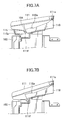
- an angle ⁇ formed by a horizontal plane H and the operating surface of the operating surface unit 111 is 7°.
- the angle ⁇ is selected from the range of 5° to 10° with which the non-handicapped person can see the operating surface easily when a height h (see Fig. 1) of the operating surface of the operating surface unit 111 is 900 mm to 1,100 mm.
- the angle ⁇ formed by the horizontal plane H and the operating surface of the operating surface unit 111 is 15°.
- the angle ⁇ is preferably within the range of 10° to 18° when the operating surface of the operating surface unit 111 has the height described above. If the angle ⁇ is less than 10°, a handicapped person in a wheelchair cannot see the operating surface easily; if it exceeds 18°, a non-handicapped person cannot see the operating surface easily.
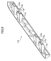
- the angle holding member 115 has the same length as that of the operating surface unit 111 and serves as a cover, so that when the operating surface unit 111 is raised, no gap is formed under it.
- the main body of the angle holding member 115 has a crank-shaped section, so it does not warp easily.
- the angle holding member 115 has four insertion pieces 115a, 115b, 115c, and 115d each having an inverted-U shaped cross section, and two locking target portions 115e and 115f each having an inverted-U shaped cross section similarly and a flat surface at its distal end.
- the flat surfaces at the distal ends of the locking target portions 115e and 115f respectively have screw holes 115g.
- the locking target portions 115e and 115f are hollow portions having open lower sides. The hollow portions have openings in the front surface of the apparatus main body 100, as shown in Fig. 3.
- Machine screws 103 can be mounted in and removed from the hollow portions by inserting a screwdriver through the openings.
- the operating surface unit 111 has a recess 111a in its lower surface.
- the distal end of the insertion piece 115a is inserted in the recess 111a, so the angle holding member 115 and operating surface unit 111 lock with each other.
- the operating surface unit 111 also has recesses 115b, 115c, and 115d (not shown) corresponding to the other three insertion pieces 115b, 115c, and 115d.
- the operating surface unit 111 With the operating surface unit 111 being removed from the apparatus main body as in Fig. 5, first, the operating surface unit 111 is fitted. This fitting operation is performed such that the pins 111e at the two ends are inserted at predetermined positions between the plate-like projections 112a and the upper-surface proximal ends 118b of the support brackets 118 from the direction of the arrow a of Fig. 5.
- the respective insertion pieces 115a, 115b, 115c, and 115d are fitted in the recesses 111a 115b, 115c, and 115d of the operating surface unit 111, and the distal end of the locking target portion 115e abuts against a locking portion 101 of the apparatus main body 100.
- the locking portion 101 has a female screw hole 101a.
- the screw hole 115g of the locking target portion 115e is aligned to the female screw hole 101a, and the machine screw 103 is screwed into the two holes, thus fixing the angle holding member 115.
- Each machine screw 103 can be fastened by inserting a screwdriver through the opening (see Fig. 3) of the locking target portion 115e or 115f in the front surface of the apparatus main body 100, as described above.
- the angle holding member 115 is fixed between the apparatus main body 100 and the operating surface unit 111, and the operating surface unit 111 is fixed to the operating section external unit 112.
- the operating section external unit 112 is integral with the apparatus main body 100, the operating surface unit 111 is fixed to the apparatus main body 100.
- a gap is formed between a lower surface 111g of the operating surface unit 111 and an opposing receiving surface 100a of the apparatus main body 100, as shown in Fig. 6A.
- a sufficiently large strength can be secured by the rigidity of the operating surface unit 111 itself and that of the angle holding member 115.
- the operating surface unit 111 will not flex or break.
- the operating surface unit 111 is switched from the position for the non-handicapped person to the position (lower position) for the handicapped person in the following manner.
- a screwdriver is inserted through the openings of the locking target portions 115e and 115f shown in Fig. 3, and the machine screws 103 are loosened and removed. When the two machine screws are removed, the angle holding member 115 is separated from the apparatus main body 100.
- the four insertion pieces 115a, 115b, 115c, and 115d disengage from the corresponding recesses 111a, 115b, 115c, and 115d, so that the angle holding member 115 can be removed from the apparatus main body 100.
- the operating surface unit 111 can pivot about the pins 111e as an axis.
- the distal end of the operating surface unit 111 is lowered.
- the lower surface 111g of the operating surface unit 111 and the receiving surface 100a of the apparatus main body 100 come into contact with each other and stop at the position shown in Figs. 6B and 7B.
- a screw hole 111j (see Fig. 6A) of a projecting locking target portion 111h on the lower surface 111g of the operating surface unit 111 coincides with the female screw hole 101a of the locking portion 101.
- the corresponding machine screw 103 is inserted in the screw hole 111j and female screw hole 101a, and is fastened.
- the operating surface unit 111 is fixed at the lower position (the state with the angle ⁇ of 15°) to serve for the handicapped person.
- the same locking portion 101 of the apparatus main body 100 can serve for attaching and removing the angle holding member 115.
- the arrangement can be simplified.
- the apparatus main body 100 When relocating the apparatus main body 100, it is done so by applying a force to the operating section external unit 112 by pushing or holding its two ends. Since the operating section external unit 112 is fixed to the apparatus main body 100, it is solid and will not be damaged during relocation. Since the operating surface unit 111 need not be touched at all, the apparatus main body 100 can be relocated without damaging the operating surface unit 111.
- the operating section external unit 112 surrounds the three surfaces, i.e., the right and left surfaces and the rear surface, of the operating surface unit 111.
- the operating section external unit 112 is always in contact with the operating surface unit 111 even when the operating surface unit 111 pivots as described above. In practice, however, it is difficult to always maintain the contact state through all of the three surfaces, but a gap may form. Then, a small foreign substance such as a clip may drop through the gap.
- a sealing member 116 formed of an elastic member is adhered to the contact portion of the operating surface unit 111 and operating section external unit 112.
- a sheet made of foamed polyurethane, rubber, or the like can be used as the sealing member 116. Since the operating surface unit 111 pivots, the sealing member 116 comes into slidable contact with it. A groove is formed in one of the two opposing contact surfaces, and the sealing member 116 formed of the elastic member is fitted and fixed in the groove to project outside the groove. Even when that portion of the sealing member 116 which projects from the groove comes into press contact with the other contact surface and slides by the pivot motion, the gap between the two contact surfaces can be constantly sealed stably.
- the operating section external unit 112 surrounds the operating surface unit 111 from the three directions, but alternatively can surround it from only the right and left ends. If the operating section is not long enough to reach from one end to the other end of the image forming apparatus, the operating section external unit 112 may be provided only at one end of the image forming apparatus.
- the female screw hole 101a and recess 111a serving as a locking portion for fixing the angle holding member 115 are formed in the apparatus main body 100, but it suffices as far as they are formed in a portion fixed to the apparatus main body 100, e.g., in the operating section external unit 112. In the present invention, such locking portion and the operating section external unit 112 as a whole are called the apparatus main body.
- two different angles can be obtained by attaching and removing one angle holding member 115.
- a plurality of angle holding members 115 may be prepared, and angle change in three or more steps can be realized.
Landscapes
- Physics & Mathematics (AREA)
- General Physics & Mathematics (AREA)
- Engineering & Computer Science (AREA)
- Microelectronics & Electronic Packaging (AREA)
- Electrophotography Configuration And Component (AREA)
- Accessory Devices And Overall Control Thereof (AREA)
- Facsimiles In General (AREA)
Abstract
Description
Claims (15)
- An image forming apparatus having, on an upper surface of an apparatus main body, an operating section which can be divided into an operating surface unit in which an angle of an operating surface with respect to a horizontal plane can be changed, and an operating section external unit formed outside said operating surface unit and including at least an upper-surface corner end of said apparatus main body, comprisingwherein either said locking target portion provided to said angle holding member or said locking target portion provided to said operating surface unit is selectively locked by said locking portion of said apparatus main body in order to support said operating surface unit with said apparatus main body such that said operating surface of said operating surface unit is held at a plurality of angles with respect to the horizontal plane.an angle holding member for holding the angle of the operating surface with respect to the horizontal plane,a plurality of locking portions formed on said apparatus main body, anda plurality of locking target portions which are formed on said angle holding member and said operating surface unit and which can respectively be locked by said plurality of locking portions,
- An apparatus according to claim 1, wherein said angle holding member serves as a cover for covering a gap between said apparatus main body and said operating surface unit, and is detachably provided to said apparatus main body.
- An apparatus according to claim 1, wherein engagement of said locking portions and said locking target portions is an arrangement of threadably engaging a machine screw in a female screw hole, and said machine screw can be mounted and detached through a front surface of said apparatus main body.
- An apparatus according to claim 2, wherein engagement of said locking portions and said locking target portions is an arrangement of threadably engaging a machine screw in a female screw hole, and said machine screw can be mounted and detached through a front surface of said apparatus main body.
- An apparatus according to claim 1, wherein a sealing member formed of an elastic member is adhered between said operating surface unit and said operating section external unit.
- An apparatus according to claim 2, wherein a sealing member formed of an elastic member is adhered between said operating surface unit and said operating section external unit.
- An apparatus according to claim 3, wherein a sealing member formed of an elastic member is adhered between said operating surface unit and said operating section external unit.
- An apparatus according to claim 1, wherein when a height from a floor surface to the operating surface of said operating surface unit is 900 mm to 1,100 mm, an angle of the operating surface with respect to the horizontal plane is 5° to 10°.
- An apparatus according to claim 2, wherein when a height from a floor surface to the operating surface of said operating surface unit is 900 mm to 1,100 mm, an angle of the operating surface with respect to the horizontal plane is 5° to 10°.
- An apparatus according to claim 3, wherein when a height from a floor surface to the operating surface of said operating surface unit is 900 mm to 1,100 mm, an angle of the operating surface with respect to the horizontal plane is 5° to 10°.
- An apparatus according to claim 4, wherein when a height from a floor surface to the operating surface of said operating surface unit is 900 mm to 1,100 mm, an angle of the operating surface with respect to the horizontal plane is 5° to 10°.
- An apparatus according to claim 1, wherein when a height from a floor surface to the operating surface of said operating surface unit is 900 mm to 1,100 mm, an angle of the operating surface with respect to the horizontal plane is 10° to 18°.
- An apparatus according to claim 2, wherein when a height from a floor surface to the operating surface of said operating surface unit is 900 mm to 1,100 mm, an angle of the operating surface with respect to the horizontal plane is 10° to 18°.
- An apparatus according to claim 3, wherein when a height from a floor surface to the operating surface of said operating surface unit is 900 mm to 1,100 mm, an angle of the operating surface with respect to the horizontal plane is 10° to 18°.
- An apparatus according to claim 4, wherein when a height from a floor surface to the operating surface of said operating surface unit is 900 mm to 1,100 mm, an angle of the operating surface with respect to the horizontal plane is 10° to 18°.
Applications Claiming Priority (2)
| Application Number | Priority Date | Filing Date | Title |
|---|---|---|---|
| JP2002152307 | 2002-05-27 | ||
| JP2002152307A JP4052016B2 (en) | 2002-05-27 | 2002-05-27 | Image forming apparatus |
Publications (2)
| Publication Number | Publication Date |
|---|---|
| EP1367453A2 true EP1367453A2 (en) | 2003-12-03 |
| EP1367453A3 EP1367453A3 (en) | 2009-12-02 |
Family
ID=29417146
Family Applications (1)
| Application Number | Title | Priority Date | Filing Date |
|---|---|---|---|
| EP03253208A Withdrawn EP1367453A3 (en) | 2002-05-27 | 2003-05-22 | Image forming apparatus |
Country Status (3)
| Country | Link |
|---|---|
| US (1) | US6865353B2 (en) |
| EP (1) | EP1367453A3 (en) |
| JP (1) | JP4052016B2 (en) |
Cited By (1)
| Publication number | Priority date | Publication date | Assignee | Title |
|---|---|---|---|---|
| WO2006098206A1 (en) | 2005-03-15 | 2006-09-21 | Ricoh Company, Ltd. | Image forming apparatus |
Families Citing this family (19)
| Publication number | Priority date | Publication date | Assignee | Title |
|---|---|---|---|---|
| USD567848S1 (en) | 2004-03-15 | 2008-04-29 | Murata Kikai Kabushiki Kaisha | Data processing machine |
| USD549769S1 (en) * | 2004-03-15 | 2007-08-28 | Murata Kikai Kabushiki Kaisha | Data processing machine |
| USD521056S1 (en) * | 2004-03-20 | 2006-05-16 | Ricoh Company, Ltd. | Full color multi-function printing machine |
| CA110477S (en) * | 2004-09-28 | 2006-03-07 | Toshiba Tec Kk | Electronic copying machine |
| USD537866S1 (en) * | 2005-03-09 | 2007-03-06 | Sharp Kabushiki Kaisha | Copying machine |
| USD537109S1 (en) * | 2005-03-09 | 2007-02-20 | Sharp Kabushiki Kaisha | Copying machine |
| JP4566141B2 (en) | 2005-07-06 | 2010-10-20 | 株式会社リコー | Installation angle adjusting device and installation angle adjusting method |
| JP5041690B2 (en) | 2005-09-15 | 2012-10-03 | 株式会社リコー | Image forming device, installation angle adjustment device |
| USD687089S1 (en) * | 2011-03-18 | 2013-07-30 | Konica Minolta, Inc. | Electronic copying machine |
| USD720754S1 (en) * | 2013-01-31 | 2015-01-06 | Hewlett-Packard Development Company, L.P. | Imaging device |
| USD727413S1 (en) * | 2013-02-04 | 2015-04-21 | Ricoh Company, Ltd. | Printer |
| USD727414S1 (en) * | 2013-02-04 | 2015-04-21 | Ricoh Company, Ltd. | Printer |
| USD727415S1 (en) * | 2013-03-06 | 2015-04-21 | Ricoh Company, Ltd. | Printer |
| JP6340835B2 (en) * | 2013-05-02 | 2018-06-13 | 株式会社リコー | Image forming apparatus |
| USD726249S1 (en) * | 2013-09-17 | 2015-04-07 | Samsung Electronics Co., Ltd. | Multi-function printer |
| USD777833S1 (en) * | 2014-08-20 | 2017-01-31 | Samsung Electronics Co., Ltd. | Multi-function printer |
| USD803935S1 (en) * | 2015-10-30 | 2017-11-28 | Hewlett-Packard Development Company, L.P. | Printer |
| JP1707812S (en) | 2021-04-14 | 2022-02-17 | Electronic copier | |
| JP1779156S (en) | 2024-02-15 | 2024-09-04 | Electronic copy machine |
Family Cites Families (7)
| Publication number | Priority date | Publication date | Assignee | Title |
|---|---|---|---|---|
| JPS54113551U (en) * | 1978-01-27 | 1979-08-09 | ||
| US4251850A (en) * | 1978-03-28 | 1981-02-17 | Siemens Aktiengesellschaft | Control desk for medical apparatus, in particular for an x-ray diagnostic apparatus |
| US5589849A (en) * | 1989-07-03 | 1996-12-31 | Ditzik; Richard J. | Display monitor position adjustment apparatus |
| US5141196A (en) * | 1991-02-21 | 1992-08-25 | Monarch Marking Systems, Inc. | Keyboard support |
| US5870647A (en) * | 1992-11-09 | 1999-02-09 | Canon Kabushiki Kaisha | Pedestal for supporting equipment |
| US5668570A (en) * | 1993-06-29 | 1997-09-16 | Ditzik; Richard J. | Desktop computer with adjustable flat panel screen |
| US6654068B1 (en) * | 2000-01-04 | 2003-11-25 | International Business Machines Corporation | Brake mechanism for controlling the tilt of a computer display |
-
2002
- 2002-05-27 JP JP2002152307A patent/JP4052016B2/en not_active Expired - Fee Related
-
2003
- 2003-05-21 US US10/442,878 patent/US6865353B2/en not_active Expired - Fee Related
- 2003-05-22 EP EP03253208A patent/EP1367453A3/en not_active Withdrawn
Cited By (3)
| Publication number | Priority date | Publication date | Assignee | Title |
|---|---|---|---|---|
| WO2006098206A1 (en) | 2005-03-15 | 2006-09-21 | Ricoh Company, Ltd. | Image forming apparatus |
| EP1858710A4 (en) * | 2005-03-15 | 2008-05-28 | Ricoh Kk | Image forming apparatus |
| US7822353B2 (en) | 2005-03-15 | 2010-10-26 | Ricoh Company, Ltd. | Image forming apparatus |
Also Published As
| Publication number | Publication date |
|---|---|
| US20030219273A1 (en) | 2003-11-27 |
| EP1367453A3 (en) | 2009-12-02 |
| JP4052016B2 (en) | 2008-02-27 |
| JP2003345087A (en) | 2003-12-03 |
| US6865353B2 (en) | 2005-03-08 |
Similar Documents
| Publication | Publication Date | Title |
|---|---|---|
| US6865353B2 (en) | Image forming apparatus with an adjustable, lockable operating surface | |
| CN100470442C (en) | Laptop with detachable display | |
| US5881986A (en) | Document support monitor and engageable universally positionable document holder | |
| US20030193773A1 (en) | Portable computer | |
| US10372167B1 (en) | Transmission base and electronic apparatus | |
| US20070008686A1 (en) | Display apparatus | |
| MXPA03009945A (en) | Touch screen mounting assembly for lcd monitor. | |
| WO2005000156A3 (en) | Auxiliary vertebrae connecting device | |
| EP1994450A1 (en) | Image forming device and image input device | |
| US7447005B2 (en) | Portable computer having a detachable display, the detachable display, and a supporting device to support the same | |
| US9317002B2 (en) | Image forming apparatus including an angle-adjustable operating member | |
| US20060012952A1 (en) | Electronic device installation dock | |
| US12426180B2 (en) | Display apparatus with adjustable height | |
| KR100522794B1 (en) | Monitor for refrigerator | |
| US7138593B2 (en) | Keytop component, operation key, and electronic device | |
| US20080055240A1 (en) | Display apparatus with on screen display controller | |
| US20060002063A1 (en) | Liquid crystal display device | |
| US20020043910A1 (en) | Image forming apparatus with a table top above a paper discharge area | |
| US20060226307A1 (en) | Display apparatus | |
| US20080123131A1 (en) | Operation Panel Structure | |
| JP2522514B2 (en) | Operation input device | |
| US20090103316A1 (en) | Chassis for a light source unit, a light source unit including the chassis, and a display device including the chassis | |
| JPH0990852A (en) | Housing cover mounting device for image forming device | |
| KR20100002885U (en) | Television with back cover and display module | |
| GB2301512A (en) | A pivotable protective screen frame structure |
Legal Events
| Date | Code | Title | Description |
|---|---|---|---|
| PUAI | Public reference made under article 153(3) epc to a published international application that has entered the european phase |
Free format text: ORIGINAL CODE: 0009012 |
|
| AK | Designated contracting states |
Kind code of ref document: A2 Designated state(s): AT BE BG CH CY CZ DE DK EE ES FI FR GB GR HU IE IT LI LU MC NL PT RO SE SI SK TR |
|
| AX | Request for extension of the european patent |
Extension state: AL LT LV MK |
|
| PUAL | Search report despatched |
Free format text: ORIGINAL CODE: 0009013 |
|
| AK | Designated contracting states |
Kind code of ref document: A3 Designated state(s): AT BE BG CH CY CZ DE DK EE ES FI FR GB GR HU IE IT LI LU MC NL PT RO SE SI SK TR |
|
| AX | Request for extension of the european patent |
Extension state: AL LT LV MK |
|
| AKY | No designation fees paid | ||
| REG | Reference to a national code |
Ref country code: DE Ref legal event code: 8566 |
|
| STAA | Information on the status of an ep patent application or granted ep patent |
Free format text: STATUS: THE APPLICATION IS DEEMED TO BE WITHDRAWN |
|
| 18D | Application deemed to be withdrawn |
Effective date: 20100603 |